EP1232883B1 - Suspension hydropneumatique de véhicule - Google Patents
Suspension hydropneumatique de véhicule Download PDFInfo
- Publication number
- EP1232883B1 EP1232883B1 EP02002745A EP02002745A EP1232883B1 EP 1232883 B1 EP1232883 B1 EP 1232883B1 EP 02002745 A EP02002745 A EP 02002745A EP 02002745 A EP02002745 A EP 02002745A EP 1232883 B1 EP1232883 B1 EP 1232883B1
- Authority
- EP
- European Patent Office
- Prior art keywords
- pressure
- valve
- line
- chambers
- load
- Prior art date
- Legal status (The legal status is an assumption and is not a legal conclusion. Google has not performed a legal analysis and makes no representation as to the accuracy of the status listed.)
- Expired - Lifetime
Links
- 239000000725 suspension Substances 0.000 title claims description 24
- 230000001105 regulatory effect Effects 0.000 claims description 11
- 230000001276 controlling effect Effects 0.000 claims description 2
- 238000010586 diagram Methods 0.000 description 9
- 230000006870 function Effects 0.000 description 6
- 230000008859 change Effects 0.000 description 5
- 238000000034 method Methods 0.000 description 4
- 230000009467 reduction Effects 0.000 description 4
- 230000003068 static effect Effects 0.000 description 4
- 230000008901 benefit Effects 0.000 description 3
- 230000001419 dependent effect Effects 0.000 description 3
- 230000006872 improvement Effects 0.000 description 3
- 230000007935 neutral effect Effects 0.000 description 3
- 230000000694 effects Effects 0.000 description 2
- 238000002474 experimental method Methods 0.000 description 2
- 238000004519 manufacturing process Methods 0.000 description 2
- 230000036316 preload Effects 0.000 description 2
- 230000006399 behavior Effects 0.000 description 1
- 230000000903 blocking effect Effects 0.000 description 1
- 239000012530 fluid Substances 0.000 description 1
- 230000005484 gravity Effects 0.000 description 1
- 238000009434 installation Methods 0.000 description 1
- 239000007788 liquid Substances 0.000 description 1
- 230000008569 process Effects 0.000 description 1
Images


Classifications
-
- B—PERFORMING OPERATIONS; TRANSPORTING
- B60—VEHICLES IN GENERAL
- B60G—VEHICLE SUSPENSION ARRANGEMENTS
- B60G17/00—Resilient suspensions having means for adjusting the spring or vibration-damper characteristics, for regulating the distance between a supporting surface and a sprung part of vehicle or for locking suspension during use to meet varying vehicular or surface conditions, e.g. due to speed or load
- B60G17/02—Spring characteristics, e.g. mechanical springs and mechanical adjusting means
- B60G17/04—Spring characteristics, e.g. mechanical springs and mechanical adjusting means fluid spring characteristics
- B60G17/0408—Spring characteristics, e.g. mechanical springs and mechanical adjusting means fluid spring characteristics details, e.g. antifreeze for suspension fluid, pumps, retarding means per se
Definitions
- the invention relates to a method and a device for controlling the suspension behavior in vehicles with hydropneumatic suspension devices and highly variable axle load ratios, especially on vehicles where the front axle is exposed to a low, medium or high static load range depending on the work input and the suspension device between the unsprung and sprung Mass has double-acting hydraulic cylinder whose pressure lines are connected to a pump, with a pressure control valve is inserted into the pressure line to the annular spaces, which constantly balances the pressure in the annular spaces to a predetermined pressure value.
- a hydropneumatic suspension for motor vehicles with large Achslastsp Dahl is known to be used in the double-acting hydraulic cylinders, the cylinder chambers are connected to a first memory and the piston rod side annular spaces with a second memory, wherein a level control valve controls the altitude and a pressure-controlled valve continuously controls a predetermined pressure ratio between the pressures of the first and the second accumulator in dependence on the load of the hydropneumatic actuators.
- the pressure-controlled valve is actuated both by the pressure in the pressure line to the cylinder chambers and by the pressure in the pressure line to the annular spaces. It is achieved a continuous control function of the load of the hydropneumatic actuators.
- the annulus pressure is regulated depending on the load.
- a more economical, simpler embodiment is contained in DE 42 42 448 C1, with the advantage of being able to use load-sensing pumps. After load changes and subsequent up or Abregelvor réellen static load changes are corrected. A pressure regulating valve is used which keeps the pressure level in the annular space spring circuit constant. At medium loads, the suspension is hard and sometimes uncomfortable.
- the invention is therefore based on the object to provide a control in which the tolerance requirements are defused for economical production, a low installation volume is made possible and the required rapid pressure adjustment is realized.
- the low load range of the front axle of the vehicle the area of the sprung axle load is understood, which occurs when the vehicle is provided at its rear end with a load, such as a plow.
- the high load range is when the front of the vehicle, a charger or the like is attached.
- the mean load range is for an unloaded vehicle.
- the solution of the problem is inventively achieved in a method or device of the type mentioned in that is raised in low load range at the front of the pressure in the annular spaces of the spring cylinder.
- the pressure in the annulus is reduced for the purpose of increasing comfort and in the low load range, the spring rate hardens by annulus pressure increase.
- the controller can be tuned so that the pressure in the annular spaces for the medium and high load case can remain constant. On the other hand, it is also possible to increase the annulus pressure even at higher load on the front axle.
- the increase of the annulus pressure can be set to different values.
- the values are to be matched to the tractor size and the respective load conditions and should be in the order of 20 - 40 bar in connection with the ring surface of the spring cylinder.
- the reservoir design can be tuned so that the pressure in the annuli can remain constant in both the medium and high load ranges
- the device for carrying out the method provides for the use of a pilot valve, which is controlled by the inlet pressure to the cylinder chambers and the discharge pressure.
- the pressure regulating valve equipped with a preload piston regulates a lower and an upper pressure value.
- the pressure to be regulated is determined by the pilot control.
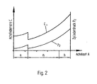
- the axle spring rate C and the cylinder pressure P z in relation to the axle load A are plotted on the front axle of a vehicle at a constant annular space pressure P R.
- the curve C shows the course of the axle spring rate C and the curve P the course of the cylinder pressure on the axle load A again.
- the axle load A is divided into a low n, middle m and high h load range.
- the low load range n is present when the vehicle is provided at its rear end with a load. This can for example be a plow in a farm tractor.
- the Vorderachsfederung is then relieved and is located in the low load range n.
- the front axle then has its highest axle load.
- the average load range m of the axle load is given when the vehicle is not loaded with devices either at the front or at the rear.
- the load limits are determined constructively and are matched to the tractor type with the selected attachments.
- the axle spring rate C depends on the selected gas preload and the volume of the hydraulic accumulator. If the axle spring rate C for the average load case m is tuned for high ride comfort, then this setting always has the consequence that the axle strikes in the low load range n without additional damper functions in unacceptable dimensions in the end stops. This can be avoided by hardening the axle spring rate in the low load range by annulus pressure increase.
- FIG. 2 and 3 the effect of annulus pressure increase in the curve of the axle spring rate C and the cylinder pressure P z is shown.
- the annulus pressure increase takes place only in the low load range n.
- Fig. 3 shows the diagram, although in the high load range h a Federratenverhärtung is required.
- the curves C 1 and C 2 are created . It was found that in both embodiments, a high level of ride comfort in the middle load range m is achieved.
- the idea underlying the invention is applicable in principle to all vehicles which are provided with hydropneumatic suspension devices and in which, depending on their workload, large axle load ratios occur.
- the pilot-operated pressure control valve is equipped with an external reaction pressure tap, which allows compensation of the internal flow resistances in small-shaped control blocks and thus causes the required accelerated pressure changes in the annulus.
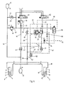
- FIG. 4 shows a circuit diagram for a tractor vehicle in which the suspension device has double-acting hydraulic cylinders whose pressure chambers can be connected to a load-sensing pump.
- the spring cylinders 1 and 2 are provided which are arranged between the unsprung and sprung masses, not shown.
- the spring cylinders 1 and 2 have the piston chambers 3 and 4, which are separated by the piston 5 and 6 of the annular spaces 7 and 8.
- the piston rods 9 and 10 are guided out of the spring cylinders 1 and 2 sealed to the outside.
- the two annular spaces 7 and 8 are connected to each other by the connecting line 11 and connected to the hydraulic accumulator 12.
- a second connecting line 13 connects the piston chambers 3 and 4.
- the connecting line 13 is connected via a line 14 to the hydraulic accumulator 15.
- In the line 14 opens the supply line 16, in which a pilot-operated check valve 17 is installed.
- the two check valves 17 and 21 open automatically in the direction of the piston chambers 3 and 4 or annular spaces 7 and 8. They can be unlocked via the control line 24 and the branching off lines 22 and 23 for a liquid flow in the opposite direction.
- the control line 24 is connected to the supply line 19.
- the pressure regulating valve 20 is inserted, with the pressure port P, discharge port T and the pressure port A for the regulated pressure.
- the drain line 26 is connected, which leads to a reservoir.
- the conduit 14 and the supply line 63 are connected to the drain line 26 via the drain lines 27 and 28, in which shut-off valves 29 and 30 are installed.
- the line 14 and the drain line 26 are connected via an intermediate line 60, in which a pressure relief valve 31 is inserted.
- the supply lines 16 and 19 are respectively connected to a solenoid valve 61 and 62, which are provided with the pressure ports P and the drain ports T.
- the valves 61 and 62 serve the level control function, which connect the supply lines 16 and 19 with a load-sensing pump or a reservoir depending on the level position of the vehicle.
- the lines 16 and 19 are connected to the drain port T. This is the neutral position.
- the serving as level control valves 61 and 62 are de-energized and are in their neutral position. Both supply lines 16 and 19 are connected to the drain T as shown in the circuit diagram. Due to the then missing control pressure, the check valves 17 and 21 can not be unlocked. They are closed and the piston chambers 3 and 4 as well as the annular spaces 7 and 8 are separated from any supply or discharge. The connections to the hydraulic accumulators 12 and 15 remain but so that the suspension of the vehicle is guaranteed. By the unpressurized State of the supply line 19, the control line 35 to the load-sensing pump is depressurized, since it can relieve the feed line 24 via the check valve 39. The load-sensing pump can then be operated in stand-by mode with comparatively low power requirement.
- the change in distance is tapped via a height sensor whose signal is converted into an electronically filtered control signals energizes the solenoid valves 61 and 62 and thus switches into Aufregelfunktion.
- the supply lines 16 and 19 are connected to the pump pressure P and via the line 19 and the pressure in the control line 24 is increased and the check valves 17, 21 and 50 unlocked.
- the shuttle valve 36 the pressures at the check valves 17 and 21 are fed, which feeds the highest pressure in the control line 35, so that the load-sensing pump can adjust to the required pressure level.
- Pressure fluid flows into the pressure line 14 and increases the pressure in the memory 15 to the required static pressure and then via line 13 into the cylinder chambers 3 and 4 until the level position is reached and the valves 61 and 62 switch back to their neutral position.
- the pressure in the annular spaces 7 and 8 and in the accumulator 12 is regulated by the 2-stage pressure control valve 20 to a predefined by the pilot valve 56 load-dependent pressure level.
- the Pilot valve 56 is acted upon via the control line 53 with the cylinder pressure from the pressure connection 16 and transmits the pressure control valve 20 via the control line 40 to be controlled pressure level in such a way that the pressure applied in the pilot valve 56 acts against a spring and pressure-dependent moves a piston, the in the middle and high pressure level in the load cases m and h, the control line 40 connects to the drain line 26 and thus switches without pressure and low line connects the line 40 to the pressure line 63 so that in the low load range n pressure oil flows to the control chamber 54 and the biasing piston 55th the control spring 41 in the control valve 20 biases higher and thus to increase the spring rate, a higher annular space pressure level is regulated.
- the control pressure for the control function of the pressure control valve 20 is externally tapped between the check valve 21 and an inserted before the connecting line 11 throttle 18, which is used to vote the control time in the branch 52 and is via the pilot operated check valve 50, the control line 51 to unlock with the Control line 24 is connected to the control line 42 connected.
- valve 62 is energized and switches to Abregelwolf in which it is ensured that the check valves 17 and 21 remain unlocked or unlocked. Pressure oil can then flow out via the unlocked check valve 17 via the line 16 and flow through the releasable check valve 21 pressure medium for adjusting the pressure levels until the level position is reached again.
- the pilot valve 56 it is possible to form the pilot valve 56 with double reversal, so even in the high Loading range h to achieve a harder spring rate, the control line 40 connected to the pressure line 19 and the pressure level is raised in the annulus.
- the pilot valve 56 may be formed as a 3-position valve.
- the pressure regulator 70 in cooperation with the throttle 71 in the pressure line 16, known from patent application DE 197 190 75, is used to control the Druckschzu- and outflow to the cylinder spring circuit, which results from the bond between the cylinder chambers 3 and 4 with the spring accumulator 15.
Landscapes
- Engineering & Computer Science (AREA)
- Mechanical Engineering (AREA)
- Vehicle Body Suspensions (AREA)
Claims (8)
- Dispositif de commande de la suspension de véhicules avec des rapports de charge fortement variables et un dispositif de suspension hydropneumatique, dans lequel des vérins élastiques (1, 2) sont disposés entre les masses suspendues et les masses non suspendues, vérins qui comprennent des chambres de piston (3, 4) portant la charge et des chambres annulaires (7, 8) sous pression entourant de façon étanche la tige de piston, dans lequel les chambres de piston (3, 4) sont raccordées à un premier accumulateur hydraulique (15) et les chambres annulaires (7, 8) sont raccordées à un deuxième accumulateur hydraulique (12) et il est prévu une soupape de réglage de pression (20), qui est placée dans la conduite sous pression (19) vers les chambres annulaires (7, 8), caractérisé en ce que la soupape de réglage de pression (20) est commandée par une soupape de commande pilote (56) qui est actionnée par la pression d'alimentation (Pz) vers les chambres de piston (3, 4) et qui commute la soupape de réglage de pression (20) à un étage de réglage plus élevé lorsque l'on descend en dessous d'une pression d'alimentation prédéterminée (Pz) dans la conduite d'alimentation (16) vers les chambres de piston (3, 4).
- Dispositif selon la revendication 1, caractérisé en ce que la soupape de commande pilote (56), formée par une soupape à double inversion, commute la soupape de réglage de pression (20) sur l'étage de réglage plus élevé pour un niveau de pression bas et haut de la pression d'alimentation (Pz).
- Dispositif selon la revendication 1 ou 2, caractérisé en ce que la soupape de commande pilote (56) est une soupape magnétique à 3/2 voies, qui est commutée par un capteur de pression dans la pression d'alimentation (Pz).
- Dispositif selon l'une quelconque des revendications 1 à 3, caractérisé en ce que la conduite de commande (42) pour le ressort de réglage (41) de la soupape de réglage de pression (20) est raccordée à la conduite d'alimentation (63) vers les chambres annulaires (7, 8) entre le clapet anti-retour (21) et les chambres annulaires (7, 8).
- Dispositif selon l'une quelconque des revendications 1 à 4, caractérisé en ce que la conduite de commande (42) comporte un clapet anti-retour (50) déblocable.
- Dispositif selon l'une quelconque des revendications 1 à 5, caractérisé en ce qu'un étranglement (18) est placé entre le raccord (52) de la conduite de commande (42) à la conduite d'alimentation (60) et la conduite de raccordement (11) des chambres annulaires (7, 8).
- Dispositif selon l'une quelconque des revendications 1 à 6, caractérisé en ce que la conduite de commande de déblocage (51) du clapet anti-retour (50) est raccordée à la conduite de commande (24) des clapets anti-retour (17, 21) des conduites d'alimentation (16, 19).
- Dispositif selon l'une quelconque des revendications 1 à 7, caractérisé en ce que la pression des chambres annulaires (PR) est commutée en deux étages de pression présentant une différence allant jusque 50 bar en fonction de la pression (Pz) régnant dans les chambres de piston (3, 4).
Applications Claiming Priority (2)
| Application Number | Priority Date | Filing Date | Title |
|---|---|---|---|
| DE10107631A DE10107631B4 (de) | 2001-02-15 | 2001-02-15 | Verfahren und Einrichtung zur Steuerung des Federungsverhaltens bei Fahrzeugen mit hydropneumatischen Federungseinrichtungen und stark veränderbaren Achslastverhältnissen |
| DE10107631 | 2001-02-15 |
Publications (3)
| Publication Number | Publication Date |
|---|---|
| EP1232883A2 EP1232883A2 (fr) | 2002-08-21 |
| EP1232883A3 EP1232883A3 (fr) | 2004-09-22 |
| EP1232883B1 true EP1232883B1 (fr) | 2007-01-17 |
Family
ID=7674509
Family Applications (1)
| Application Number | Title | Priority Date | Filing Date |
|---|---|---|---|
| EP02002745A Expired - Lifetime EP1232883B1 (fr) | 2001-02-15 | 2002-02-07 | Suspension hydropneumatique de véhicule |
Country Status (3)
| Country | Link |
|---|---|
| US (1) | US6786492B2 (fr) |
| EP (1) | EP1232883B1 (fr) |
| DE (2) | DE10107631B4 (fr) |
Families Citing this family (19)
| Publication number | Priority date | Publication date | Assignee | Title |
|---|---|---|---|---|
| AUPR249901A0 (en) * | 2001-01-10 | 2001-02-01 | Kinetic Pty Limited | Vehicle suspension roll control system |
| US20060064071A1 (en) * | 2001-11-06 | 2006-03-23 | Possis Medical, Inc. | Gas inflation/evacuation system incorporating a reservoir and removably attached sealing system for a guidewire assembly having an occlusive device |
| DE10232769B4 (de) * | 2002-07-18 | 2005-08-25 | Carl Freudenberg Kg | Hydropneumatische Achsfederung für Fahrzeuge für Fahrzeuge mit stark wechselden Achslasten |
| DE10257008A1 (de) * | 2002-12-06 | 2004-06-17 | Continental Aktiengesellschaft | Aus Feder und Dämpfer bestehende Federungsanordnung |
| DE10306756B4 (de) * | 2003-02-17 | 2007-01-04 | Carl Freudenberg Kg | Hydropneumatische Federungseinrichtung für Fahrzeuge |
| DE10337601A1 (de) * | 2003-08-16 | 2005-03-10 | Deere & Co | Hydropneumatische Federungseinrichtung |
| DE10338534B3 (de) * | 2003-08-19 | 2005-01-27 | Carl Freudenberg Kg | Vorrichtung zur Steuerung des Federungsverhaltens von Fahrzeugen mit wechselnden Achslasten |
| EP1711357A1 (fr) * | 2004-01-28 | 2006-10-18 | LuK Lamellen und Kupplungsbau Beteiligungs KG | Dispositif de stabilisation de roulis |
| DE102004058618A1 (de) * | 2004-12-04 | 2006-06-08 | Carl Freudenberg Kg | Anordnung zur Beeinflussung von Bewegungen eines Kraftfahrzeugs und Einrichtung zur Verwendung in einer Anordnung |
| US7615031B2 (en) | 2005-09-01 | 2009-11-10 | Medrad, Inc. | Gas inflation/evacuation system incorporating a multiple element valved guidewire assembly having an occlusive device |
| DE102007050190A1 (de) | 2007-10-20 | 2009-04-23 | Daimler Ag | Gasfederspeicher |
| DE102008012704A1 (de) * | 2008-03-05 | 2009-09-10 | Deere & Company, Moline | Hydraulische Federungsanordnung |
| DE102008046632A1 (de) | 2008-09-10 | 2009-05-07 | Daimler Ag | Gasfederspeicher |
| DE102009037536A1 (de) * | 2009-08-17 | 2011-03-24 | Benteler Automobiltechnik Gmbh | Vorrichtung zur aktiven Spureinstellung |
| DE102012106185B3 (de) * | 2012-07-10 | 2013-11-21 | Fsp Fluid Systems Partners Holding Ag | Steueranordnung für ein hydropneumatisches Federungssystem sowie hydropneumatisches Federungssystem mit einer solchen Steueranordnung |
| DE102012022030A1 (de) * | 2012-11-12 | 2014-05-15 | Deere & Company | Federungseinrichtung für eine beweglich gelagerte Fahrzeugachse |
| DE102013102069A1 (de) | 2013-03-01 | 2014-09-04 | Fsp Fluid Systems Partners Holding Ag | Proportional-Wegeventil sowie hydraulische Schaltung und hydropneumatisches Federungssystem mit einem derartigen Ventil |
| EP3330111B1 (fr) * | 2016-12-02 | 2023-02-01 | Husco International, Inc. | Système de suspension pour un véhicule tout terrain |
| US10029533B1 (en) * | 2017-01-23 | 2018-07-24 | Caterpillar Underground Mining Pty Ltd | Vehicle suspension control system |
Family Cites Families (7)
| Publication number | Priority date | Publication date | Assignee | Title |
|---|---|---|---|---|
| EP0535116B1 (fr) * | 1990-06-28 | 1995-09-06 | Zahnradfabrik Friedrichshafen Ag | Suspension hydropneumatique pour vehicules |
| DE4127801A1 (de) * | 1991-08-22 | 1993-02-25 | Hemscheidt Maschf Hermann | Hydropneumatisches federungssystem fuer eine fahrzeug-liftachse |
| DE4242448C1 (de) * | 1992-12-16 | 1994-03-31 | Integral Hydraulik Co | Hydro-pneumatische Federungseinrichtung |
| DE19719076C2 (de) * | 1997-05-06 | 2000-05-04 | Integral Accumulator Kg | Hydropneumatische Federungseinrichtung für Fahrzeuge mit großen Lastverhältnissen |
| DE19719075B4 (de) * | 1997-05-06 | 2004-07-01 | Integral Accumulator Kg | Doppeltwirkendes Ventil zur Strombeeinflussung, insbesondere für hydro-pneumatische Federungseinrichtungen für Fahrzeuge mit großen Lastverhältnissen |
| DE19719077C2 (de) * | 1997-05-06 | 2000-05-04 | Integral Accumulator Kg | Hydropneumatische Federung für Fahrzeuge |
| DE19748224B4 (de) * | 1997-10-31 | 2005-07-14 | Deere & Company, Moline | Hydropneumatische Achsfederung für angetriebene Fahrzeugachsen |
-
2001
- 2001-02-15 DE DE10107631A patent/DE10107631B4/de not_active Expired - Lifetime
-
2002
- 2002-02-07 DE DE50209257T patent/DE50209257D1/de not_active Expired - Lifetime
- 2002-02-07 EP EP02002745A patent/EP1232883B1/fr not_active Expired - Lifetime
- 2002-02-13 US US10/075,794 patent/US6786492B2/en not_active Expired - Lifetime
Also Published As
| Publication number | Publication date |
|---|---|
| US6786492B2 (en) | 2004-09-07 |
| EP1232883A3 (fr) | 2004-09-22 |
| US20020171209A1 (en) | 2002-11-21 |
| DE50209257D1 (de) | 2007-03-08 |
| EP1232883A2 (fr) | 2002-08-21 |
| DE10107631A1 (de) | 2002-09-05 |
| DE10107631B4 (de) | 2007-04-05 |
Similar Documents
| Publication | Publication Date | Title |
|---|---|---|
| EP1232883B1 (fr) | Suspension hydropneumatique de véhicule | |
| EP3233544B1 (fr) | Châssis de véhicule automobile | |
| EP0535116B1 (fr) | Suspension hydropneumatique pour vehicules | |
| DE19703872A1 (de) | Hydraulischer Dämpfer | |
| DE10232769B4 (de) | Hydropneumatische Achsfederung für Fahrzeuge für Fahrzeuge mit stark wechselden Achslasten | |
| DE68908846T2 (de) | Hydraulisches Fahrzeugaufhängungssystem. | |
| EP1963118B1 (fr) | Suspension hydropneumatique de l'essieu de vehicules automobiles | |
| DE3824611A1 (de) | Feder-daempfer-system fuer fahrzeuge | |
| EP1238834A2 (fr) | Système de suspension active d'un véhicule | |
| EP1778508A1 (fr) | Dispositif de suspenson | |
| DE10107644B4 (de) | Hydropneumatische Federung für Fahrzeuge mit stark wechselnden Achslasten | |
| DE102014004337A1 (de) | Kommunalfahrzeug | |
| DE102012019863A1 (de) | Fahrzeug | |
| EP3398418A1 (fr) | Système hydraulique d'une machine à usage agricole ou de travaux publics | |
| DE19719076C2 (de) | Hydropneumatische Federungseinrichtung für Fahrzeuge mit großen Lastverhältnissen | |
| DE4221088C2 (de) | Aufhängungssystem für Fahrzeuge | |
| DE10306756B4 (de) | Hydropneumatische Federungseinrichtung für Fahrzeuge | |
| EP3464908A1 (fr) | Système de vannes | |
| DE102021121843B3 (de) | Hydropneumatisches Federungssystem | |
| EP4096943B1 (fr) | Système de suspension hydropneumatique pour véhicules | |
| DE3901349C2 (fr) | ||
| DE4118822C2 (fr) | ||
| DE4026849C2 (de) | Ventilanordnung zum Erzeugen eines Steuerdrucks in einer hydraulischen Anlage | |
| DE19949152C2 (de) | Hydropneumatische Federung | |
| DE10338534B3 (de) | Vorrichtung zur Steuerung des Federungsverhaltens von Fahrzeugen mit wechselnden Achslasten |
Legal Events
| Date | Code | Title | Description |
|---|---|---|---|
| PUAI | Public reference made under article 153(3) epc to a published international application that has entered the european phase |
Free format text: ORIGINAL CODE: 0009012 |
|
| AK | Designated contracting states |
Kind code of ref document: A2 Designated state(s): AT BE CH CY DE DK ES FI FR GB GR IE IT LI LU MC NL PT SE TR |
|
| AX | Request for extension of the european patent |
Free format text: AL;LT;LV;MK;RO;SI |
|
| PUAL | Search report despatched |
Free format text: ORIGINAL CODE: 0009013 |
|
| AK | Designated contracting states |
Kind code of ref document: A3 Designated state(s): AT BE CH CY DE DK ES FI FR GB GR IE IT LI LU MC NL PT SE TR |
|
| AX | Request for extension of the european patent |
Extension state: AL LT LV MK RO SI |
|
| 17P | Request for examination filed |
Effective date: 20040813 |
|
| AKX | Designation fees paid |
Designated state(s): AT BE CH CY DE DK ES FI FR GB GR IE IT LI LU MC NL PT SE TR |
|
| 17Q | First examination report despatched |
Effective date: 20050228 |
|
| GRAP | Despatch of communication of intention to grant a patent |
Free format text: ORIGINAL CODE: EPIDOSNIGR1 |
|
| GRAS | Grant fee paid |
Free format text: ORIGINAL CODE: EPIDOSNIGR3 |
|
| GRAA | (expected) grant |
Free format text: ORIGINAL CODE: 0009210 |
|
| AK | Designated contracting states |
Kind code of ref document: B1 Designated state(s): AT BE CH CY DE DK ES FI FR GB GR IE IT LI LU MC NL PT SE TR |
|
| PG25 | Lapsed in a contracting state [announced via postgrant information from national office to epo] |
Ref country code: NL Free format text: LAPSE BECAUSE OF FAILURE TO SUBMIT A TRANSLATION OF THE DESCRIPTION OR TO PAY THE FEE WITHIN THE PRESCRIBED TIME-LIMIT Effective date: 20070117 Ref country code: DK Free format text: LAPSE BECAUSE OF FAILURE TO SUBMIT A TRANSLATION OF THE DESCRIPTION OR TO PAY THE FEE WITHIN THE PRESCRIBED TIME-LIMIT Effective date: 20070117 Ref country code: IE Free format text: LAPSE BECAUSE OF FAILURE TO SUBMIT A TRANSLATION OF THE DESCRIPTION OR TO PAY THE FEE WITHIN THE PRESCRIBED TIME-LIMIT Effective date: 20070117 Ref country code: FI Free format text: LAPSE BECAUSE OF FAILURE TO SUBMIT A TRANSLATION OF THE DESCRIPTION OR TO PAY THE FEE WITHIN THE PRESCRIBED TIME-LIMIT Effective date: 20070117 |
|
| REG | Reference to a national code |
Ref country code: GB Ref legal event code: FG4D Free format text: NOT ENGLISH |
|
| REG | Reference to a national code |
Ref country code: CH Ref legal event code: EP |
|
| PG25 | Lapsed in a contracting state [announced via postgrant information from national office to epo] |
Ref country code: MC Free format text: LAPSE BECAUSE OF NON-PAYMENT OF DUE FEES Effective date: 20070228 Ref country code: CH Free format text: LAPSE BECAUSE OF NON-PAYMENT OF DUE FEES Effective date: 20070228 Ref country code: LI Free format text: LAPSE BECAUSE OF NON-PAYMENT OF DUE FEES Effective date: 20070228 |
|
| REG | Reference to a national code |
Ref country code: IE Ref legal event code: FG4D Free format text: LANGUAGE OF EP DOCUMENT: GERMAN |
|
| REF | Corresponds to: |
Ref document number: 50209257 Country of ref document: DE Date of ref document: 20070308 Kind code of ref document: P |
|
| PG25 | Lapsed in a contracting state [announced via postgrant information from national office to epo] |
Ref country code: SE Free format text: LAPSE BECAUSE OF FAILURE TO SUBMIT A TRANSLATION OF THE DESCRIPTION OR TO PAY THE FEE WITHIN THE PRESCRIBED TIME-LIMIT Effective date: 20070417 |
|
| PG25 | Lapsed in a contracting state [announced via postgrant information from national office to epo] |
Ref country code: ES Free format text: LAPSE BECAUSE OF FAILURE TO SUBMIT A TRANSLATION OF THE DESCRIPTION OR TO PAY THE FEE WITHIN THE PRESCRIBED TIME-LIMIT Effective date: 20070428 |
|
| PG25 | Lapsed in a contracting state [announced via postgrant information from national office to epo] |
Ref country code: PT Free format text: LAPSE BECAUSE OF FAILURE TO SUBMIT A TRANSLATION OF THE DESCRIPTION OR TO PAY THE FEE WITHIN THE PRESCRIBED TIME-LIMIT Effective date: 20070618 |
|
| NLV1 | Nl: lapsed or annulled due to failure to fulfill the requirements of art. 29p and 29m of the patents act | ||
| GBV | Gb: ep patent (uk) treated as always having been void in accordance with gb section 77(7)/1977 [no translation filed] |
Effective date: 20070117 |
|
| REG | Reference to a national code |
Ref country code: IE Ref legal event code: FD4D |
|
| REG | Reference to a national code |
Ref country code: CH Ref legal event code: PL |
|
| PLBE | No opposition filed within time limit |
Free format text: ORIGINAL CODE: 0009261 |
|
| STAA | Information on the status of an ep patent application or granted ep patent |
Free format text: STATUS: NO OPPOSITION FILED WITHIN TIME LIMIT |
|
| PG25 | Lapsed in a contracting state [announced via postgrant information from national office to epo] |
Ref country code: GB Free format text: LAPSE BECAUSE OF FAILURE TO SUBMIT A TRANSLATION OF THE DESCRIPTION OR TO PAY THE FEE WITHIN THE PRESCRIBED TIME-LIMIT Effective date: 20070117 |
|
| 26N | No opposition filed |
Effective date: 20071018 |
|
| BERE | Be: lapsed |
Owner name: CARL FREUDENBERG K.G. Effective date: 20070228 |
|
| PG25 | Lapsed in a contracting state [announced via postgrant information from national office to epo] |
Ref country code: BE Free format text: LAPSE BECAUSE OF NON-PAYMENT OF DUE FEES Effective date: 20070228 |
|
| PG25 | Lapsed in a contracting state [announced via postgrant information from national office to epo] |
Ref country code: FR Free format text: LAPSE BECAUSE OF FAILURE TO SUBMIT A TRANSLATION OF THE DESCRIPTION OR TO PAY THE FEE WITHIN THE PRESCRIBED TIME-LIMIT Effective date: 20070907 Ref country code: GR Free format text: LAPSE BECAUSE OF FAILURE TO SUBMIT A TRANSLATION OF THE DESCRIPTION OR TO PAY THE FEE WITHIN THE PRESCRIBED TIME-LIMIT Effective date: 20070418 |
|
| PG25 | Lapsed in a contracting state [announced via postgrant information from national office to epo] |
Ref country code: AT Free format text: LAPSE BECAUSE OF NON-PAYMENT OF DUE FEES Effective date: 20070207 |
|
| PG25 | Lapsed in a contracting state [announced via postgrant information from national office to epo] |
Ref country code: FR Free format text: LAPSE BECAUSE OF FAILURE TO SUBMIT A TRANSLATION OF THE DESCRIPTION OR TO PAY THE FEE WITHIN THE PRESCRIBED TIME-LIMIT Effective date: 20070117 |
|
| PG25 | Lapsed in a contracting state [announced via postgrant information from national office to epo] |
Ref country code: CY Free format text: LAPSE BECAUSE OF FAILURE TO SUBMIT A TRANSLATION OF THE DESCRIPTION OR TO PAY THE FEE WITHIN THE PRESCRIBED TIME-LIMIT Effective date: 20070117 |
|
| PG25 | Lapsed in a contracting state [announced via postgrant information from national office to epo] |
Ref country code: LU Free format text: LAPSE BECAUSE OF NON-PAYMENT OF DUE FEES Effective date: 20070207 |
|
| PG25 | Lapsed in a contracting state [announced via postgrant information from national office to epo] |
Ref country code: TR Free format text: LAPSE BECAUSE OF FAILURE TO SUBMIT A TRANSLATION OF THE DESCRIPTION OR TO PAY THE FEE WITHIN THE PRESCRIBED TIME-LIMIT Effective date: 20070117 |
|
| PGFP | Annual fee paid to national office [announced via postgrant information from national office to epo] |
Ref country code: IT Payment date: 20210226 Year of fee payment: 20 |
|
| PGFP | Annual fee paid to national office [announced via postgrant information from national office to epo] |
Ref country code: DE Payment date: 20210301 Year of fee payment: 20 |