EP1232884A2 - Barre anti-dévers à biellette de liaison réglable pour ajuster la rigidité en torsion - Google Patents
Barre anti-dévers à biellette de liaison réglable pour ajuster la rigidité en torsion Download PDFInfo
- Publication number
- EP1232884A2 EP1232884A2 EP02003450A EP02003450A EP1232884A2 EP 1232884 A2 EP1232884 A2 EP 1232884A2 EP 02003450 A EP02003450 A EP 02003450A EP 02003450 A EP02003450 A EP 02003450A EP 1232884 A2 EP1232884 A2 EP 1232884A2
- Authority
- EP
- European Patent Office
- Prior art keywords
- piston
- cylinder
- plate
- piston rod
- roll bar
- Prior art date
- Legal status (The legal status is an assumption and is not a legal conclusion. Google has not performed a legal analysis and makes no representation as to the accuracy of the status listed.)
- Withdrawn
Links
- 239000000725 suspension Substances 0.000 claims abstract description 29
- 239000012530 fluid Substances 0.000 claims abstract description 28
- 230000004044 response Effects 0.000 claims description 2
- 230000011664 signaling Effects 0.000 claims 1
- 230000001133 acceleration Effects 0.000 description 5
- 230000004048 modification Effects 0.000 description 2
- 238000012986 modification Methods 0.000 description 2
- 229910000831 Steel Inorganic materials 0.000 description 1
- 230000008859 change Effects 0.000 description 1
- 230000000694 effects Effects 0.000 description 1
- 230000005684 electric field Effects 0.000 description 1
- 238000009434 installation Methods 0.000 description 1
- 238000007789 sealing Methods 0.000 description 1
- 239000007787 solid Substances 0.000 description 1
- 239000010959 steel Substances 0.000 description 1
Images

Classifications
-
- F—MECHANICAL ENGINEERING; LIGHTING; HEATING; WEAPONS; BLASTING
- F16—ENGINEERING ELEMENTS AND UNITS; GENERAL MEASURES FOR PRODUCING AND MAINTAINING EFFECTIVE FUNCTIONING OF MACHINES OR INSTALLATIONS; THERMAL INSULATION IN GENERAL
- F16F—SPRINGS; SHOCK-ABSORBERS; MEANS FOR DAMPING VIBRATION
- F16F9/00—Springs, vibration-dampers, shock-absorbers, or similarly-constructed movement-dampers using a fluid or the equivalent as damping medium
- F16F9/32—Details
- F16F9/44—Means on or in the damper for manual or non-automatic adjustment; such means combined with temperature correction
- F16F9/46—Means on or in the damper for manual or non-automatic adjustment; such means combined with temperature correction allowing control from a distance, i.e. location of means for control input being remote from site of valves, e.g. on damper external wall
- F16F9/466—Throttling control, i.e. regulation of flow passage geometry
- F16F9/467—Throttling control, i.e. regulation of flow passage geometry using rotary valves
-
- B—PERFORMING OPERATIONS; TRANSPORTING
- B60—VEHICLES IN GENERAL
- B60G—VEHICLE SUSPENSION ARRANGEMENTS
- B60G17/00—Resilient suspensions having means for adjusting the spring or vibration-damper characteristics, for regulating the distance between a supporting surface and a sprung part of vehicle or for locking suspension during use to meet varying vehicular or surface conditions, e.g. due to speed or load
- B60G17/015—Resilient suspensions having means for adjusting the spring or vibration-damper characteristics, for regulating the distance between a supporting surface and a sprung part of vehicle or for locking suspension during use to meet varying vehicular or surface conditions, e.g. due to speed or load the regulating means comprising electric or electronic elements
- B60G17/016—Resilient suspensions having means for adjusting the spring or vibration-damper characteristics, for regulating the distance between a supporting surface and a sprung part of vehicle or for locking suspension during use to meet varying vehicular or surface conditions, e.g. due to speed or load the regulating means comprising electric or electronic elements characterised by their responsiveness, when the vehicle is travelling, to specific motion, a specific condition, or driver input
- B60G17/0162—Resilient suspensions having means for adjusting the spring or vibration-damper characteristics, for regulating the distance between a supporting surface and a sprung part of vehicle or for locking suspension during use to meet varying vehicular or surface conditions, e.g. due to speed or load the regulating means comprising electric or electronic elements characterised by their responsiveness, when the vehicle is travelling, to specific motion, a specific condition, or driver input mainly during a motion involving steering operation, e.g. cornering, overtaking
-
- B—PERFORMING OPERATIONS; TRANSPORTING
- B60—VEHICLES IN GENERAL
- B60G—VEHICLE SUSPENSION ARRANGEMENTS
- B60G17/00—Resilient suspensions having means for adjusting the spring or vibration-damper characteristics, for regulating the distance between a supporting surface and a sprung part of vehicle or for locking suspension during use to meet varying vehicular or surface conditions, e.g. due to speed or load
- B60G17/06—Characteristics of dampers, e.g. mechanical dampers
- B60G17/08—Characteristics of fluid dampers
-
- B—PERFORMING OPERATIONS; TRANSPORTING
- B60—VEHICLES IN GENERAL
- B60G—VEHICLE SUSPENSION ARRANGEMENTS
- B60G21/00—Interconnection systems for two or more resiliently-suspended wheels, e.g. for stabilising a vehicle body with respect to acceleration, deceleration or centrifugal forces
- B60G21/02—Interconnection systems for two or more resiliently-suspended wheels, e.g. for stabilising a vehicle body with respect to acceleration, deceleration or centrifugal forces permanently interconnected
- B60G21/04—Interconnection systems for two or more resiliently-suspended wheels, e.g. for stabilising a vehicle body with respect to acceleration, deceleration or centrifugal forces permanently interconnected mechanically
- B60G21/05—Interconnection systems for two or more resiliently-suspended wheels, e.g. for stabilising a vehicle body with respect to acceleration, deceleration or centrifugal forces permanently interconnected mechanically between wheels on the same axle but on different sides of the vehicle, i.e. the left and right wheel suspensions being interconnected
- B60G21/055—Stabiliser bars
- B60G21/0551—Mounting means therefor
- B60G21/0553—Mounting means therefor adjustable
- B60G21/0558—Mounting means therefor adjustable including means varying the stiffness of the stabiliser
-
- B—PERFORMING OPERATIONS; TRANSPORTING
- B60—VEHICLES IN GENERAL
- B60G—VEHICLE SUSPENSION ARRANGEMENTS
- B60G2200/00—Indexing codes relating to suspension types
- B60G2200/30—Rigid axle suspensions
- B60G2200/34—Stabilising mechanisms, e.g. for lateral stability
-
- B—PERFORMING OPERATIONS; TRANSPORTING
- B60—VEHICLES IN GENERAL
- B60G—VEHICLE SUSPENSION ARRANGEMENTS
- B60G2202/00—Indexing codes relating to the type of spring, damper or actuator
- B60G2202/10—Type of spring
- B60G2202/13—Torsion spring
- B60G2202/135—Stabiliser bar and/or tube
-
- B—PERFORMING OPERATIONS; TRANSPORTING
- B60—VEHICLES IN GENERAL
- B60G—VEHICLE SUSPENSION ARRANGEMENTS
- B60G2202/00—Indexing codes relating to the type of spring, damper or actuator
- B60G2202/20—Type of damper
- B60G2202/24—Fluid damper
-
- B—PERFORMING OPERATIONS; TRANSPORTING
- B60—VEHICLES IN GENERAL
- B60G—VEHICLE SUSPENSION ARRANGEMENTS
- B60G2202/00—Indexing codes relating to the type of spring, damper or actuator
- B60G2202/30—Spring/Damper and/or actuator Units
- B60G2202/32—The spring being in series with the damper and/or actuator
-
- B—PERFORMING OPERATIONS; TRANSPORTING
- B60—VEHICLES IN GENERAL
- B60G—VEHICLE SUSPENSION ARRANGEMENTS
- B60G2204/00—Indexing codes related to suspensions per se or to auxiliary parts
- B60G2204/10—Mounting of suspension elements
- B60G2204/12—Mounting of springs or dampers
- B60G2204/122—Mounting of torsion springs
- B60G2204/1224—End mounts of stabiliser on wheel suspension
-
- B—PERFORMING OPERATIONS; TRANSPORTING
- B60—VEHICLES IN GENERAL
- B60G—VEHICLE SUSPENSION ARRANGEMENTS
- B60G2204/00—Indexing codes related to suspensions per se or to auxiliary parts
- B60G2204/62—Adjustable continuously, e.g. during driving
-
- B—PERFORMING OPERATIONS; TRANSPORTING
- B60—VEHICLES IN GENERAL
- B60G—VEHICLE SUSPENSION ARRANGEMENTS
- B60G2400/00—Indexing codes relating to detected, measured or calculated conditions or factors
- B60G2400/10—Acceleration; Deceleration
- B60G2400/104—Acceleration; Deceleration lateral or transversal with regard to vehicle
-
- B—PERFORMING OPERATIONS; TRANSPORTING
- B60—VEHICLES IN GENERAL
- B60G—VEHICLE SUSPENSION ARRANGEMENTS
- B60G2400/00—Indexing codes relating to detected, measured or calculated conditions or factors
- B60G2400/20—Speed
- B60G2400/204—Vehicle speed
-
- B—PERFORMING OPERATIONS; TRANSPORTING
- B60—VEHICLES IN GENERAL
- B60G—VEHICLE SUSPENSION ARRANGEMENTS
- B60G2400/00—Indexing codes relating to detected, measured or calculated conditions or factors
- B60G2400/40—Steering conditions
- B60G2400/41—Steering angle
- B60G2400/412—Steering angle of steering wheel or column
-
- B—PERFORMING OPERATIONS; TRANSPORTING
- B60—VEHICLES IN GENERAL
- B60G—VEHICLE SUSPENSION ARRANGEMENTS
- B60G2500/00—Indexing codes relating to the regulated action or device
- B60G2500/10—Damping action or damper
- B60G2500/104—Damping action or damper continuous
-
- B—PERFORMING OPERATIONS; TRANSPORTING
- B60—VEHICLES IN GENERAL
- B60G—VEHICLE SUSPENSION ARRANGEMENTS
- B60G2500/00—Indexing codes relating to the regulated action or device
- B60G2500/10—Damping action or damper
- B60G2500/11—Damping valves
-
- B—PERFORMING OPERATIONS; TRANSPORTING
- B60—VEHICLES IN GENERAL
- B60G—VEHICLE SUSPENSION ARRANGEMENTS
- B60G2800/00—Indexing codes relating to the type of movement or to the condition of the vehicle and to the end result to be achieved by the control action
- B60G2800/01—Attitude or posture control
- B60G2800/012—Rolling condition
Definitions
- the present invention relates to an apparatus for use in a vehicle suspension and, more particularly, to an apparatus for use in helping to resist vehicle roll during a turn.
- Anti-roll bars also known as sway bars, are used in vehicle suspensions for helping to resist vehicle roll during a turn. Anti-roll bars may be used in both the front and rear suspensions of a vehicle.
- Anti-roll bars are generally U-shaped and include opposite first and second end portions and an intermediate portion.
- the first end portion is fixed to the right-hand side of the vehicle suspension and the second end portion is fixed to the left-hand side of the vehicle suspension.
- the first end portion and the second end portion of the anti-roll bar move relative to one another.
- the intermediate portion of the anti-roll bar may be subjected to a torsional force.
- the torsional stiffness, i.e., the resistance to the torsional force, of the intermediate portion of the anti-roll bar helps to resist vehicle roll during the turn.
- the stiffness of the anti-roll bar is also known to increase the spring rate of the vehicle suspension.
- the independence of the right-hand side and the left-hand side of the vehicle suspension may be affected by connecting the two sides with the anti-roll bar. Consequently, the vehicle ride may be affected, especially when the vehicle is traveling in a linear direction.
- Known systems have attached at least one end portion of the anti-roll bar to the vehicle suspension with an actuator.
- the actuator includes a cylinder and a piston that is movable within the cylinder.
- the piston divides the cylinder into two variable volume chambers.
- the known systems further include a source of fluid and a control valve, both of which are independent of the actuator.
- the control valve is connected to each chamber of the piston by a hydraulic conduit.
- the control valve has three positions. In a first position, the control valve interconnects the hydraulic conduit connected to each chamber of the actuator, thereby allowing unrestricted movement of the piston in the cylinder. In a second position, the control valve sends hydraulic fluid to the first chamber and receives hydraulic fluid flowing out of the second chamber. In a third position, the control valve sends hydraulic fluid to the second chamber and receives hydraulic fluid flowing out of the first chamber.
- a system similar to that described above is disclosed in U.S. Patent No. 5,529,324.
- the known system helps to reduce the possible effects of the anti-roll bar on the spring rate of the vehicle
- the known system includes many parts and installation of the known systems on a vehicle is complex.
- This invention is an apparatus for use in a vehicle suspension.
- the apparatus comprises an anti-roll bar having opposite first and second end portions. An intermediate portion is interposed between the first and second end portions and is subjected to torsional forces when the first and second end portions move relative to one another.
- the apparatus further comprises an actuator for attaching at least one of the first and second end portions to a part of the vehicle suspension.
- the actuator comprises a cylinder for retaining fluid and a piston assembly for dividing the cylinder into two chambers.
- the piston assembly is movable within the cylinder.
- the piston assembly includes structure forming orifices for interconnecting the two chambers of the cylinder. A fluid flow area of the orifices is adjustable to vary a resistance to relative movement of the first and second end portions of the anti-roll bar.
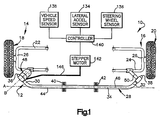
- Fig. 1 schematically illustrates a portion of a vehicle suspension 10 including an apparatus 12 of the present invention.
- the suspension 10 includes a left-hand side 14 and a right-hand side 16.
- a first steerable wheel 18 is connected to the left-hand side 14 of the suspension 10 and a second steerable wheel 20 is connected to the right-hand side 16 of the suspension 10.
- the left-hand side 14 of the suspension 10 includes a first control arm 22 and the right-hand side 16 of the suspension 10 includes a second control arm 24. Both the first and second control arms 22 and 24 are U-shaped. Steerable wheel 18 connects with a closed portion 26 of the U-shape of control arm 22. Steerable wheel 20 connects with a closed portion 27 of the U-shape of control arm 24.
- the apparatus 12 of the present invention includes an anti-roll bar 28.
- the anti-roll bar 28 includes opposite first and second end portions 30 and 32, respectively.
- An intermediate portion 34 is interposed between the respective end portions 30 and 32.
- the anti-roll bar 28 has a generally U-shaped configuration with the first and second end portions 30 and 32 forming two legs of the U-shape and the intermediate portion 34 forming a closed end of the U-shape.
- the intermediate portion 34 of the anti-roll bar 28 extends linearly.
- the intermediate portion 34 has a length that is approximately eighty percent of the total length of the anti-roll bar 28.
- the total length of the anti-roll bar 28 is the length from a terminal end 36 of the first end portion 30 to a terminal end 38 of the second end portion 32.
- Brackets 40 and 42 support the intermediate portion 34 of the anti-roll bar 28.
- the brackets 40 and 42 attach to the vehicle frame (not shown) in a known manner and allow the intermediate portion 34 of the anti-roll bar 28 to freely rotate about an axis A passing through the center of the intermediate portion 34 of the anti-roll bar 28.
- the first end portion 30 of the anti-roll bar 28 extends from the left-hand end 44 of the intermediate portion 34 of the anti-roll bar 28.
- the first end portion 30 extends from the intermediate portion 34 at an angle of approximately forty-five degrees relative to axis A and has a length that is approximately one-tenth of the total length of the anti-roll bar 28.
- the first end portion 30 terminates at terminal end 36.
- the second end portion 32 of the anti-roll bar 28 is a mirror image of the first end portion 30.
- the second end portion 32 extends from a right-hand end 46 of the intermediate portion 34 of the anti-roll bar 28.
- the second end portion 32 extends from the intermediate portion 34 at an angle of approximately forty-five degrees relative to axis A and has a length that is approximately one-tenth of the total length of the anti-roll bar 28.
- the second end portion 32 is within the same plane as the first end portion 30.
- the second end portion 32 terminates at terminal end 38.
- the apparatus 12 further includes an actuator 48.
- the actuator 48 attaches the first end portion 30 of the anti-roll bar 28 to the first control arm 22 of the vehicle suspension 10. A detailed description of the actuator 48 is found below.
- a link member 50 attaches the second end portion 32 of the anti-roll bar 28 to the second control arm 24 of the vehicle suspension 10.
- the link member 50 is a solid steel rod that extends between the second control arm 24 and the second end portion 32 of the anti-roll bar 28.
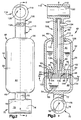
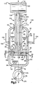
- Figs. 2 and 3 illustrate the actuator 48 of the apparatus 12 of the present invention.
- the actuator 48 includes a cylinder 52 for retaining a fluid 54 and a piston assembly 56. Description of the actuator 48 will be made with reference to axis B. As shown in Fig. 1, axis A represents a generally horizontal axis; whereas, axis B represents a generally vertical axis.
- the cylinder 52 includes an axially extending, cylindrical main body portion 58.
- the cylindrical main body portion 58 is centered on axis B.
- the main body portion 58 of the cylinder 52 includes an outer wall 60 and an inner wall 62.
- First and second axial ends 64 and 66 close axially opposite ends of the main body portion 58 of the cylinder 52.
- the first axial end 64 of the cylinder 52 is annular and includes an opening 68 that is centered on axis B. As illustrated in Fig. 3, the opening 68 has a diameter of approximately fifty percent of the inner diameter of the main body portion 58 of the cylinder 52.
- the second axial end 66 of the cylinder 52 is domed and completely closes the cylinder 52.
- a first mounting member 70 for attaching the cylinder 52 to the first control arm 22 extends from the center of the second axial end 66 of the cylinder 52 in a direction axially opposite the main body portion 58 of the cylinder 52.
- the first mounting member 70 illustrated in Figs. 2 and 3 includes a cylindrical rod 72 and a first tubular bushing 74.
- the cylindrical rod 72 is centered on axis B.
- One end of the cylindrical rod 72 is fixed to the second axial end 66 of the cylinder 52 and the other end of the cylindrical rod 72 is fixed to an outer surface 76 (Fig. 3) of the first tubular bushing 74.
- the first tubular bushing 74 includes a channel 78 that extends in a direction perpendicular to axis B.
- a part of the first control arm 22 extends through the channel 78 of tubular bushing 74.
- a fastener (not shown) fixes the first tubular bushing 74 to the first control arm 22.
- the piston assembly 56 of the actuator 48 includes a piston 80 (Fig. 3) formed by first and second plates 82 and 84, respectively.
- the piston 80 is enclosed within the cylinder 52 and is movable within the cylinder 52 along axis B.
- the piston 80 divides the cylinder 52 into two variable volume chambers 81 and 83.
- the first plate 82 forming the piston 80 is flat and circular.
- the first plate 82 is centered on axis B and extends radially outwardly to engage the inner wall 62 of the main body portion 58 of the cylinder 52.
- the first plate 82 has an upper surface 86 and a lower surface 88.
- the upper surface 86 of the first plate 82 is nearest the first axial end 64 of the cylinder 52 and the lower surface 88 is nearest the second axial end 66 of the cylinder 52.
- An annular ring (not shown) may extend circumferentially around the first plate 82 for sealing the first plate 82 against the inner wall 62 of the cylinder 52.
- An opening 90 extends axially through the first plate 82.
- the opening 90 is centered on axis B and in the illustrated embodiment has a diameter of approximately twenty-five percent of the diameter of the first plate 82. Those skilled in the art will recognize that the size of the opening 90 may be varied.
- the first plate 82 of the piston 80 further includes a plurality of axially extending passages 92.
- the axially extending passages 92 are arranged in a circular array about axis B.
- the first plate 82 has six axially extending passages 92, two of which are shown in Fig. 3.
- annular groove 94 extends into the lower surface 88 of the first plate 82 in an area between the central opening 90 and the axially extending passages 92.
- the annular groove 94 completely surrounds the central opening 90.
- the annular groove 94 has a rectangular cross-sectional profile for receiving a portion of an o-ring 96.
- the second plate 84 forming the piston 80 is also flat and circular.
- the second plate 84 is centered on axis B. As illustrated in Fig. 3, the second plate 84 also extends radially outwardly to engage the inner wall 62 of the main body portion 58 of the cylinder 52.
- the second plate 84 may have a diameter that differs from the diameter of the first plate 82.
- the second plate 84 has an upper surface 98 and a lower surface 100.
- the upper surface 98 of the second plate 84 engages the lower surface 88 of the first plate 82.
- the lower surface 100 of the second plate 84 is nearest the second axial end 66 of the cylinder 52.
- the second plate 84 of the piston 80 also includes a plurality of axially extending passages 102 arranged in a circular array about axis B.
- the second plate has six axially extending passages 102, as shown in Figs. 4(a)-(c).
- the axially extending passages 102 of the second plate 84 may be aligned, depending upon rotation of the second plate 84 relative to the first plate 82, with the axially extending passages 92 of the first plate 82 of the piston 80.
- annular groove 104 extends into the upper surface 98 of the second plate 84 in an area corresponding to the annular groove 94 in the first plate 82.
- the annular groove 104 in the second plate 84 has a rectangular cross-sectional profile for receiving a portion of o-ring 96.
- the piston assembly 56 further includes first and second piston rods 106 and 108, respectively.
- the first piston rod 106 attaches to the upper surface 86 of the first plate 82 of the piston 80.
- the first piston rod 106 is welded to the first plate 82.
- the first piston rod 106 is movable axially with the piston 80.
- the first piston rod 106 is tubular and includes an outer surface 110 and an inner surface 112.
- the outer surface 110 has a diameter that is slightly smaller than the diameter of the opening 68 on the first axial end 64 of the cylinder 52.
- the inner surface 112 defines a channel 114 that extends axially through the first piston rod 106.
- the channel 114 is coaxial with and aligns with the opening 90 extending through the first plate 82 of the piston 80.
- a second mounting member 116 is partially formed from an end of the first piston rod 106 opposite the piston 80.
- the second mounting member 116 further includes a second tubular bushing 118.
- the second tubular bushing 118 includes a channel 120 that extends perpendicular to both axis B and the channel 78 of the first tubular bushing 74. As shown in Fig. 1, the first end portion 30 of the anti-roll bar 28 extends through the channel 120 of the second tubular bushing 118.
- a fastener (not shown) fixes the second tubular bushing 118 to the first end portion 30 of the anti-roll bar 28.
- a slot 122 extends through the first piston rod 106 in an area near the seconding mounting member 116.
- the slot 122 extends circumferentially about axis B around a portion of the first piston rod 106.
- the second piston rod 108 is coaxial with the first piston rod 106 and extends through the channel 114 of the first piston rod 106.
- the second piston rod 108 is fixed for axial movement with the first piston rod 106.
- One end of the second piston rod 108 attaches to the upper surface 98 of the second plate 84 of the piston 80.
- An opposite end of the second piston rod 108 terminates near the second mounting member 116.
- the second piston rod 108 is spaced radially inwardly from the inner surface 112 of the first piston rod 106.
- a radially extending arm 124 is connected to the second piston rod 108.
- the radially extending arm 124 extends through the slot 122 in the first piston rod 106.
- the radially extending arm 124 is secured to the second piston rod 108 such that movement of the arm 124 in the slot 122 causes rotation of the second piston rod 108 and consequently, rotation of the second plate 84 of the piston 80.
- Two bearings 126 and 128 rotatably attach the second piston rod 108 to the first piston rod 106.
- An outer race of each bearing 126 and 128 is secured to the inner surface 112 of the first piston rod 106.
- An inner race of each bearing 126 and 128 attaches to the second piston rod 108.
- the second piston rod 108 is rotatable relative to the first piston rod 106.
- the axis of rotation for the second piston rod 108 is axis B.
- rotation of the second piston rod 108 relative to the first piston rod 106 causes rotation of the second plate 84 of the piston 80 relative to the 'first plate 82 of the piston 80.
- the actuator 48 also includes at least two seals 130 and 132.
- a first seal 130 is secured in the opening 68 in the first axial end 64 of the cylinder 52.
- the first seal 130 engages the outer surface 110 of the first piston rod 106 and prevents fluid 54 leakage from the cylinder 52 as the piston assembly 56 moves axially through the opening 68 in the first axial end 64 of the cylinder 52.
- a second seal 132 is interposed between the first and second plates 82 and 84 of the piston 80 for preventing fluid 54 leakage between the first and second plates 82 and 84 and into the channel 114 of the first piston rod 106.
- a portion of the second seal 132 seats in the annular groove 94 on the lower surface 88 of the first plate 82 and another portion seats in the annular groove 104 on the upper surface 98 of the second plate 84.
- the second seal 132 is an o-ring 96 that allows the second plate 84 to rotate relative to the first plate 82.
- the apparatus 12 further includes a plurality of sensors 134, 136, and 138 and a controller 140.
- the plurality of sensors 134, 136, and 138 includes a lateral acceleration sensor 134, a steering wheel rotation sensor 136, and a vehicle speed sensor 138.
- Each sensor 134, 136, and 138 is electrically connected to the controller 140.
- the lateral acceleration sensor 134 continuously senses the lateral acceleration of the vehicle and generates an electrical signal indicative of the sensed lateral acceleration.
- the steering wheel rotation sensor 136 continuously senses the magnitude and rate of rotation of the vehicle steering wheel and generates an electrical signal indicative of these parameters.
- the vehicle speed sensor 138 continuously senses the vehicle speed and generates an electrical signal indicative of the speed.
- the controller 140 includes a microprocessor.
- the controller 140 receives the signals generated by the lateral acceleration sensor 134, the steering wheel rotation sensor 136, and the vehicle speed sensor 138.
- the controller 140 analyzes the respective signals and generates a control signal for controlling the torsional stiffness of the anti-roll bar 28.
- the controller 140 sends the control signal to an electric motor used for actuating the actuator 48.
- the electric motor is a stepper motor 142.
- Linkage shown schematically at 146, connects the stepper motor 142 to the arm 124 extending radially from the second piston rod 108.
- the stepper motor 142 may be connected to the second piston rod 108 in another manner, such as through a gear assembly.
- the stepper motor 142 Upon receiving the control signal from the controller 140, the stepper motor 142 causes the arm 124 extending radially from second piston rod 108 to move through the slot 122 in the first piston rod 106. Movement of the arm 124 causes rotation of the second piston rod 108, and consequently, rotation of the second plate 84 of the piston 80 relative to the first plate 82 of the piston 80.
- Rotation of the second plate 84 of the piston 80 relative to the first plate 82 of the piston 80 adjusts the flow area of orifices 144 (Fig. 3) formed in the piston 80 by alignment of the axially extending passages 92 of the first plate 82 and axially extending passages 102 of the second plate 84 of the piston 80.
- Figs. 4(a)-4(c) illustrate the adjustment of the flow area of the orifices 144.
- Fig. 4(a) illustrates the orifices 144 of the piston 80 when the axially extending passages 92 of the first plate 82 are completely aligned with the axially extending passages 102 of the second plate 84.
- each orifice 144 is equal to the flow area of the axially extending passages 102 in the second plate 84.
- Fig. 4(b) shows the axially extending passages 92 of the first plate 82 partially aligned with the axially extending passages 102 of the second plate 84.
- the flow area of the orifices 144 in Fig. 4(b) is less than the flow area shown in Fig. 4(a) by the area of the first plate 82 that covers the axially extending passages 102 in the second plate 84.
- Fig. 4(c) shows no alignment between the axially extending passages 92 of the first plate 82 and the axially extending passages 102 of the second plate 84.
- the orifices 144 of the piston 80 shown in Fig. 4(c) have no flow area.
- the resistance to movement of the piston 80 within the cylinder 52 is inversely proportional to the flow area of the orifices 144.
- the orifices 144 are fully open, as shown in Fig. 4(a)
- the resistance to movement of the piston 80 will be minimized and a force along axis B will cause the piston 80 to move within cylinder 52.
- fluid 54 will flow through the orifices 144 and the volume of one chamber, for example chamber 81, will increase, while the volume of the other chamber 83 will decrease.
- the orifices 144 are completely closed, as shown in Fig.
- the resistance to movement of the piston 80 will be maximized and no fluid 54 may flow between the chambers 81 and 83 of the cylinder 52.
- the piston 80 will be locked in place within the cylinder 52 as the fluid 54 will resist axial movement of the piston 80.
- the actuator 48 affects the torsional resistance of the anti-roll bar 28. Since the first end portion 30 of the anti-roll bar 28 is attached to a part of the vehicle suspension 10 by the actuator 48, the movement of the piston 80 in the cylinder 52 of the actuator 48 affects the movement of the first end portion 30 of the anti-roll bar 28. When the orifices 144 of the piston 80 are fully opened, the piston 80 will move easily within the cylinder 52 and the first end portion 30 of the anti-roll bar 28 will move easily with respect to the second end portion 32 of the anti-roll bar 28. As a result, the anti-roll bar 28 will have virtually no resistance to roll of the vehicle. This is most likely to occur when the vehicle is traveling in a straight line.
- the piston 80 of the actuator 48 When the orifices 144 of the piston 80 of the actuator 48 are completely closed, the piston 80 will not move within the cylinder 52 of the actuator 48 and the resistance to movement of the first end portion 30 of the anti-roll bar 28 relative to the second end portion 32 of the anti-roll bar 28 is maximized. As a result, the torsional stiffness of the anti-roll bar 28 is increased and the anti-roll bar 28 will resist roll of the vehicle. This is most likely to occur when a turn is sensed. Depending upon the parameters sensed by the plurality of sensors 134, 136, and 138, the flow area of the orifices 144 may be adjusted to vary the torsional resistance of the anti-roll bar 28.
- the left-hand side 14 and the right-hand side 16 of the vehicle suspension 10 may move independently of one another with little affect from the anti-roll bar 28.
- the anti-roll bar 28 will rigidly connect the left-hand and right-hand sides 14 and 16 of the vehicle suspension 10 and help to resist roll of the vehicle during a turn.
- FIG. 5 A second embodiment of the actuator 148 of the apparatus 10 of the present invention is illustrated in Fig. 5.
- first and second electrodes 150 and 152 are attached to the inner wall 60 of the cylinder 52 of the actuator 148.
- Leads 154 electrically connect the electrodes 150 and 152 to the controller 140.
- the controller 140 is operable to provide a variable electrical field, in the form of voltage, to the electrodes 150 and 152 in response to the signals received from the plurality of sensors 134, 136, and 138.
- the fluid 54 within the cylinder 52 is an electrorheological fluid. By varying the voltage potential between the first and second electrodes 150 and 152, the viscosity of the fluid 54 can be changed.
- the fluid 54 flow through the orifices 144 is changed and resistance to movement of the piston 80 in the cylinder 52 is changed.
- the torsional stiffness of the anti-roll bar 28 can be further adjusted by controlling the viscosity of the fluid 54.
- an actuator 48 may be used to connect the second end portion 32 of the anti-roll bar 28 to the vehicle suspension 10.
- the first mounting member 70 may attach to the anti-roll bar 28 and the second mounting member 116 to a part of the vehicle suspension 10.
Landscapes
- Engineering & Computer Science (AREA)
- Mechanical Engineering (AREA)
- General Engineering & Computer Science (AREA)
- Vehicle Body Suspensions (AREA)
Applications Claiming Priority (2)
| Application Number | Priority Date | Filing Date | Title |
|---|---|---|---|
| US788080 | 2001-02-16 | ||
| US09/788,080 US6457730B1 (en) | 2001-02-16 | 2001-02-16 | Anti-roll bar with link actuator for controlling torsional rigidity |
Publications (2)
| Publication Number | Publication Date |
|---|---|
| EP1232884A2 true EP1232884A2 (fr) | 2002-08-21 |
| EP1232884A3 EP1232884A3 (fr) | 2006-03-29 |
Family
ID=25143396
Family Applications (1)
| Application Number | Title | Priority Date | Filing Date |
|---|---|---|---|
| EP02003450A Withdrawn EP1232884A3 (fr) | 2001-02-16 | 2002-02-14 | Barre anti-dévers à biellette de liaison réglable pour ajuster la rigidité en torsion |
Country Status (2)
| Country | Link |
|---|---|
| US (1) | US6457730B1 (fr) |
| EP (1) | EP1232884A3 (fr) |
Cited By (64)
| Publication number | Priority date | Publication date | Assignee | Title |
|---|---|---|---|---|
| WO2007017074A1 (fr) * | 2005-08-09 | 2007-02-15 | Bayerische Motoren Werke Aktiengesellschaft | Procede de fonctionnement conçu pour un systeme de stabilisation de roulis monoaxial d'un vehicule a deux essieux roulant sur double voie |
| CN103278198A (zh) * | 2013-06-25 | 2013-09-04 | 丁雪强 | 一种带有温度检测装置的缓冲器 |
| CN103277446A (zh) * | 2013-06-25 | 2013-09-04 | 丁雪强 | 一种适于防止滑块撞击后反弹的缓冲器的工作方法 |
| CN103291805A (zh) * | 2013-06-25 | 2013-09-11 | 苏州唐氏机械制造有限公司 | 一种可温度保护的两级缓冲器的工作方法 |
| CN103291815A (zh) * | 2013-06-25 | 2013-09-11 | 丁雪强 | 一种自动吸合、释放滑块的缓冲器的工作方法 |
| CN103291800A (zh) * | 2013-06-25 | 2013-09-11 | 苏州唐氏机械制造有限公司 | 一种带有温度检测装置的缓冲器 |
| CN103291810A (zh) * | 2013-06-25 | 2013-09-11 | 苏州唐氏机械制造有限公司 | 一种可温度保护的两级缓冲器 |
| CN103291816A (zh) * | 2013-06-25 | 2013-09-11 | 苏州唐氏机械制造有限公司 | 一种自动调节缓冲级数的两级缓冲器的工作方法 |
| CN103291826A (zh) * | 2013-06-25 | 2013-09-11 | 苏州唐氏机械制造有限公司 | 一种适于调节各级缓冲顺序的三级缓冲器的工作方法 |
| CN103291833A (zh) * | 2013-06-25 | 2013-09-11 | 苏州唐氏机械制造有限公司 | 一种带缓冲器的直线导轨 |
| CN103291819A (zh) * | 2013-06-25 | 2013-09-11 | 苏州唐氏机械制造有限公司 | 一种带有温度保护装置的两级缓冲器 |
| CN103307171A (zh) * | 2013-06-25 | 2013-09-18 | 苏州唐氏机械制造有限公司 | 根据冲击压力控制活塞运动速度的缓冲器的工作方法 |
| CN103307181A (zh) * | 2013-06-25 | 2013-09-18 | 苏州唐氏机械制造有限公司 | 一种带有温度检测装置的两级缓冲器的工作方法 |
| CN103307183A (zh) * | 2013-06-25 | 2013-09-18 | 苏州唐氏机械制造有限公司 | 一种适于吸合冲击过程中滑块的缓冲器的工作方法 |
| CN103307182A (zh) * | 2013-06-25 | 2013-09-18 | 苏州唐氏机械制造有限公司 | 一种带有温度检测装置的缓冲器的工作方法 |
| CN103307172A (zh) * | 2013-06-25 | 2013-09-18 | 苏州唐氏机械制造有限公司 | 一种带有温度保护装置的两级缓冲器的工作方法 |
| CN103307177A (zh) * | 2013-06-25 | 2013-09-18 | 苏州唐氏机械制造有限公司 | 一种自动吸合、释放滑块的缓冲器 |
| CN103307180A (zh) * | 2013-06-25 | 2013-09-18 | 苏州唐氏机械制造有限公司 | 一种适于调节各级缓冲顺序的两级缓冲器的工作方法 |
| CN103322107A (zh) * | 2013-06-25 | 2013-09-25 | 蒋春花 | 一种自动调节缓冲级数的多级缓冲器的工作方法 |
| CN103322112A (zh) * | 2013-06-25 | 2013-09-25 | 苏州唐氏机械制造有限公司 | 根据冲击压力以调节活塞运动的缓冲器的工作方法 |
| CN103335053A (zh) * | 2013-06-25 | 2013-10-02 | 蒋春花 | 一种适于逐级控制缓冲顺序的三级缓冲器 |
| CN103335056A (zh) * | 2013-06-25 | 2013-10-02 | 蒋超 | 一种适于自动调节受力缓冲的缓冲器的工作方法 |
| CN103335051A (zh) * | 2013-06-25 | 2013-10-02 | 蒋春花 | 一种适于自动调节受力缓冲的缓冲器 |
| CN103335054A (zh) * | 2013-06-25 | 2013-10-02 | 蒋超 | 一种三级缓冲器的工作方法 |
| CN103352952A (zh) * | 2013-06-25 | 2013-10-16 | 吴正明 | 一种适于实现各级均匀缓冲的三级缓冲器 |
| CN103352953A (zh) * | 2013-06-25 | 2013-10-16 | 吴正明 | 一种适于逐级控制缓冲顺序的两级缓冲器 |
| CN103352951A (zh) * | 2013-06-25 | 2013-10-16 | 吴正明 | 一种带有温度检测装置的两级缓冲器 |
| CN103398137A (zh) * | 2013-07-29 | 2013-11-20 | 苏州市世好建材新技术工程有限公司 | 全自动液压成型制砖机的工作方法 |
| CN103395630A (zh) * | 2013-07-29 | 2013-11-20 | 苏州市世好建材新技术工程有限公司 | 一种空心砌块生产线 |
| CN103398136A (zh) * | 2013-07-29 | 2013-11-20 | 苏州市世好建材新技术工程有限公司 | 一种全自动制砖系统的工作方法 |
| CN103395608A (zh) * | 2013-07-29 | 2013-11-20 | 苏州市世好建材新技术工程有限公司 | 一种制砖生产线 |
| CN103395631A (zh) * | 2013-07-29 | 2013-11-20 | 苏州市世好建材新技术工程有限公司 | 一种空心砌块生产线的工作方法 |
| CN103398135A (zh) * | 2013-07-29 | 2013-11-20 | 苏州市世好建材新技术工程有限公司 | 一种全自动制砖系统 |
| CN103395632A (zh) * | 2013-07-29 | 2013-11-20 | 苏州市世好建材新技术工程有限公司 | 空心砌块码跺装置 |
| CN103410907A (zh) * | 2013-07-29 | 2013-11-27 | 苏州市世好建材新技术工程有限公司 | 空心砌块、砖的智能码跺装置的工作方法 |
| CN103407791A (zh) * | 2013-07-29 | 2013-11-27 | 苏州市世好建材新技术工程有限公司 | 砖坯码跺装置的工作方法 |
| CN103434848A (zh) * | 2013-07-29 | 2013-12-11 | 苏州市世好建材新技术工程有限公司 | 砖坯码垛装置 |
| CN104279229A (zh) * | 2013-07-05 | 2015-01-14 | 常州轻工职业技术学院 | 带有智能控制缓冲装置的直线导轨副及工作方法 |
| CN104712699A (zh) * | 2013-06-25 | 2015-06-17 | 苏州唐氏机械制造有限公司 | 一种缓冲器 |
| CN104712698A (zh) * | 2013-06-25 | 2015-06-17 | 苏州唐氏机械制造有限公司 | 可显示介质温度的缓冲器 |
| CN104712700A (zh) * | 2013-06-25 | 2015-06-17 | 苏州唐氏机械制造有限公司 | 一种带有温度检测装置的两级缓冲器 |
| CN104728328A (zh) * | 2013-06-25 | 2015-06-24 | 苏州唐氏机械制造有限公司 | 可延长缓冲器寿命的适于吸合冲击过程中滑块的缓冲器 |
| CN104776147A (zh) * | 2013-06-25 | 2015-07-15 | 苏州唐氏机械制造有限公司 | 以弹性胶体为缓冲介质的两级缓冲器 |
| CN104776118A (zh) * | 2013-06-25 | 2015-07-15 | 苏州唐氏机械制造有限公司 | 一种直线导轨的工作方法 |
| CN104913168A (zh) * | 2013-06-25 | 2015-09-16 | 苏州唐氏机械制造有限公司 | 一种自动调节水平的工作台的工作方法 |
| CN103486186B (zh) * | 2013-08-08 | 2015-09-30 | 苏州赛斯德工程设备有限公司 | 一种装有内燃机的减震采茶机及工作方法 |
| CN104989765A (zh) * | 2013-06-25 | 2015-10-21 | 蒋超 | 三级缓冲器的工作方法 |
| CN105035669A (zh) * | 2013-07-29 | 2015-11-11 | 蒋红娟 | 码垛作业用全自动液压成型机的自动给进机 |
| CN105065540A (zh) * | 2013-06-25 | 2015-11-18 | 蒋超 | 一种处理器模块控制的适于自动调节受力缓冲的缓冲器 |
| CN105090324A (zh) * | 2013-07-29 | 2015-11-25 | 蒋盘君 | 一种处理器模块控制的液压成型机 |
| CN105090331A (zh) * | 2013-06-25 | 2015-11-25 | 蒋盘君 | 一种处理器模块控制的多级缓冲器的工作方法 |
| CN105114506A (zh) * | 2013-06-25 | 2015-12-02 | 蒋超 | 采用处理器模块控制的缓冲器及其工作方法 |
| CN105108887A (zh) * | 2013-07-29 | 2015-12-02 | 蒋红娟 | 空心砌块、砖生产用全自动液压成型制砖机 |
| CN105156548A (zh) * | 2013-07-29 | 2015-12-16 | 朱海燕 | 处理器控制的全自动液压成型机 |
| CN105221638A (zh) * | 2013-06-25 | 2016-01-06 | 蒋春花 | 处理器自动调节缓冲级数的多级缓冲器 |
| CN105240437A (zh) * | 2013-06-25 | 2016-01-13 | 蒋超 | 处理器根据冲击压力以调节活塞运动的缓冲器的工作方法 |
| CN105257776A (zh) * | 2013-07-29 | 2016-01-20 | 蒋红娟 | 液压成型制砖机的自动给进机的工作方法 |
| CN105264258A (zh) * | 2013-06-06 | 2016-01-20 | 标致·雪铁龙汽车公司 | 具有行程结束的液压缓冲的减震器 |
| CN105284292A (zh) * | 2013-08-08 | 2016-02-03 | 朱海燕 | 采用处理器模块控制活塞体组件的采茶机 |
| CN105485235A (zh) * | 2013-07-05 | 2016-04-13 | 谈雪梅 | 一种自动化生产线的送料机构的工作方法 |
| CN105638097A (zh) * | 2013-08-08 | 2016-06-08 | 吴杰 | 一种采茶机的工作方法 |
| CN106224424A (zh) * | 2013-08-08 | 2016-12-14 | 吴红平 | 一种采茶机的工作方法 |
| EP2354588A3 (fr) * | 2010-01-29 | 2016-12-21 | Stabilus GmbH | Ensemble cylindre-piston |
| CN115605358A (zh) * | 2020-03-13 | 2023-01-13 | 克里斯多夫·科克斯创意公司(Us) | 防倾杆连杆 |
Families Citing this family (44)
| Publication number | Priority date | Publication date | Assignee | Title |
|---|---|---|---|---|
| US6592136B2 (en) | 2001-07-02 | 2003-07-15 | Fox Factory, Inc. | Bicycle fork cartridge assembly |
| DE10134715A1 (de) * | 2001-07-17 | 2003-02-06 | Daimler Chrysler Ag | Vorrichtung zur Wankabstützung von Fahrzeugen |
| US7273137B2 (en) | 2001-08-30 | 2007-09-25 | Fox Factory, Inc. | Inertia valve shock absorber |
| US7128192B2 (en) | 2001-08-30 | 2006-10-31 | Fox Factory, Inc. | Inertia valve shock absorber |
| US6866276B2 (en) * | 2002-05-10 | 2005-03-15 | Meritor Light Vehicle Technology, Llc | Roll bumper stabilizer bar links |
| US10941828B2 (en) | 2002-06-25 | 2021-03-09 | Fox Factory, Inc. | Gas spring with travel control |
| US20080296814A1 (en) | 2002-06-25 | 2008-12-04 | Joseph Franklin | Gas spring with travel control |
| US7703585B2 (en) | 2002-06-25 | 2010-04-27 | Fox Factory, Inc. | Integrated and self-contained suspension assembly having an on-the-fly adjustable air spring |
| US8464850B2 (en) | 2006-11-16 | 2013-06-18 | Fox Factory, Inc. | Gas spring curve control in an adjustable-volume gas-pressurized device |
| US7963509B2 (en) | 2007-01-31 | 2011-06-21 | Fox Factory, Inc. | Travel control for a gas spring and gas spring having very short travel modes |
| EP1513696B1 (fr) * | 2003-03-28 | 2008-09-24 | Aisin Seiki Kabushiki Kaisha | Dispositif de commande de stabilisateur pour un vehicule |
| JP4303140B2 (ja) * | 2004-02-12 | 2009-07-29 | アイシン精機株式会社 | スタビライザ制御装置 |
| CN1888466A (zh) * | 2005-06-28 | 2007-01-03 | 比亚迪股份有限公司 | 一种可调阻尼减振器 |
| JP4193819B2 (ja) * | 2005-06-27 | 2008-12-10 | トヨタ自動車株式会社 | 車両用懸架装置 |
| JP2007030575A (ja) * | 2005-07-25 | 2007-02-08 | Aisin Seiki Co Ltd | スタビライザ制御装置 |
| US7699146B1 (en) | 2006-04-02 | 2010-04-20 | Fox Factory, Inc. | Suspension damper having inertia valve and user adjustable pressure-relief |
| DE102006022473A1 (de) * | 2006-05-13 | 2007-11-15 | Gustav Magenwirth Gmbh & Co. Kg | Federgabel |
| US7493199B2 (en) * | 2006-10-17 | 2009-02-17 | Trw Automotive U.S. Llc | Method of controlling a roll control system for improved vehicle dynamic control |
| US9205717B2 (en) | 2012-11-07 | 2015-12-08 | Polaris Industries Inc. | Vehicle having suspension with continuous damping control |
| CN103213469B (zh) * | 2013-04-11 | 2016-06-15 | 浙江万向系统有限公司 | 一种基于液压支撑系统的可断开式汽车稳定杆系统 |
| DE102013103825A1 (de) * | 2013-04-16 | 2014-10-16 | Dr. Ing. H.C. F. Porsche Aktiengesellschaft | Strebenelement für Kraftfahrzeuge |
| CN103291808B (zh) * | 2013-06-25 | 2015-04-29 | 苏州唐氏机械制造有限公司 | 一种适于吸合冲击过程中的滑块的缓冲器 |
| CN103291814B (zh) * | 2013-06-25 | 2015-04-29 | 苏州唐氏机械制造有限公司 | 一种适于防止滑块撞击后反弹的缓冲器 |
| CN103307170B (zh) * | 2013-06-25 | 2015-08-26 | 苏州唐氏机械制造有限公司 | 一种自动调节缓冲级数的两级缓冲器 |
| CN103307184B (zh) * | 2013-06-26 | 2016-03-09 | 苏州海而仕信息科技有限公司 | 一种适于自动调节受力缓冲的缓冲器的工作方法 |
| CN105217323A (zh) * | 2013-07-29 | 2016-01-06 | 蒋红娟 | 全自动液压成型机的处理器控制的自动给进机 |
| DE102014211939B4 (de) * | 2014-06-23 | 2025-05-08 | Ford Global Technologies, Llc | Schwingungsdämpfer, insbesondere dämpfungseinstellbarer Stoßdämpfer für Kraftfahrzeuge |
| CN104329404B (zh) * | 2014-09-19 | 2017-02-15 | 江苏今达纺织实业有限公司 | 双层错孔式送经机构缓冲器及其应用 |
| CN107406094B (zh) | 2014-10-31 | 2020-04-14 | 北极星工业有限公司 | 用于控制车辆的系统和方法 |
| DE102015214460B4 (de) * | 2015-07-30 | 2017-03-09 | Schaeffler Technologies AG & Co. KG | Elastischer Fahrwerkslenker für ein Fahrzeug |
| CA3043481C (fr) | 2016-11-18 | 2022-07-26 | Polaris Industries Inc. | Vehicule a suspension reglable |
| US10406884B2 (en) | 2017-06-09 | 2019-09-10 | Polaris Industries Inc. | Adjustable vehicle suspension system |
| US20200325509A1 (en) | 2017-09-08 | 2020-10-15 | Intrexon Corporation | Microorganisms and Methods in the Fermentation of Benzylisoquinoline Alkaloids |
| US10987987B2 (en) | 2018-11-21 | 2021-04-27 | Polaris Industries Inc. | Vehicle having adjustable compression and rebound damping |
| CN109798319A (zh) * | 2019-02-28 | 2019-05-24 | 常州市雷美特液压机械有限公司 | 阻尼式活塞杆 |
| CN110273961A (zh) * | 2019-05-22 | 2019-09-24 | 武汉船用机械有限责任公司 | 阻尼活塞及阻尼器 |
| US11173767B2 (en) * | 2019-10-22 | 2021-11-16 | Christopher Cox Creative | Hydraulic anti-roll bar link |
| MX2022015902A (es) * | 2020-07-17 | 2023-01-24 | Polaris Inc | Suspensiones ajustables y operacion de vehiculo para vehiculos recreativos todoterreno. |
| US11634003B2 (en) | 2020-12-17 | 2023-04-25 | Fox Factory, Inc. | Automated control system for an electronically controlled sway bar link |
| US12502923B2 (en) | 2022-02-23 | 2025-12-23 | Fox Factory, Inc. | Hydraulic cross-linked suspension |
| US12311720B2 (en) | 2022-02-23 | 2025-05-27 | Fox Factory, Inc. | Hydraulic cross-linked suspension |
| CN120476051A (zh) * | 2022-12-30 | 2025-08-12 | 深圳引望智能技术有限公司 | 一种弹性连接件、主动稳定杆和车辆 |
| US12145419B2 (en) | 2023-02-22 | 2024-11-19 | AirBoss Flexible Products, LLC | Adaptive stabilizer bar with cycloidal drive |
| US12522042B1 (en) | 2024-10-24 | 2026-01-13 | Fox Factory, Inc. | Linked gas chambers for e-sway disconnect |
Citations (1)
| Publication number | Priority date | Publication date | Assignee | Title |
|---|---|---|---|---|
| US5529324A (en) | 1994-08-15 | 1996-06-25 | Kelsey-Hayes Company | System and method for vehicle roll control |
Family Cites Families (25)
| Publication number | Priority date | Publication date | Assignee | Title |
|---|---|---|---|---|
| DE1138646B (de) * | 1957-04-03 | 1962-10-25 | Armin Drechsel | Als úŽ-foermige Drehstabfeder ausgebildeter Kurvenstabilisator mit veraenderlicher Wirkung fuer zwei- oder mehrspurige Fahrzeuge, insbesondere Kraftfahrzeuge |
| FR1249681A (fr) * | 1960-03-01 | 1960-12-30 | Hoesch Ag | Amortisseur hydraulique pour véhicules |
| US3827538A (en) * | 1966-11-09 | 1974-08-06 | F Morgan | Shock absorbers |
| US3420341A (en) * | 1967-10-16 | 1969-01-07 | Jonathan N Keehn | Variable shock absorber |
| DE7346104U (de) * | 1973-12-28 | 1974-03-28 | Weisser U | Stoßdämpfer |
| US4527676A (en) | 1982-02-13 | 1985-07-09 | Atsugi Motor Parts Co., Ltd. | Variable-damping-force shock absorber |
| DE3215614A1 (de) * | 1982-04-27 | 1983-02-03 | Anna Dorothea 8000 München Sapunarow-Ryffel | Hydraulischer einrohr-stossdaempfer mit daempfungsregelung |
| JPS6064011A (ja) * | 1983-09-17 | 1985-04-12 | Nissan Motor Co Ltd | 車両におけるサスペンション制御装置 |
| US4724937A (en) * | 1984-09-04 | 1988-02-16 | General Motors Corporation | Hydraulic damper for vehicles with variable deflected disk piston valving |
| KR900009133B1 (ko) * | 1986-12-01 | 1990-12-22 | 미쓰비시지도오샤 고오교오 가부시키가이샤 | 스프링 정수 가변형 스테빌라이저 장치 |
| US5161822A (en) | 1990-11-26 | 1992-11-10 | Tlc Suspension | Tilt correction system |
| US5217245A (en) * | 1991-09-03 | 1993-06-08 | Monroe Auto Equipment Company | Switchable roll-stabilizer bar |
| US5630623A (en) | 1994-08-15 | 1997-05-20 | Kelsey Hayes | Vehicle roll control system |
| US5597180A (en) | 1994-08-15 | 1997-01-28 | Ganzel; Blaise J. | Vehicle roll control apparatus |
| US5505480A (en) | 1995-03-03 | 1996-04-09 | Ford Motor Company | Controlled stabilizer bar attachment apparatus for improved suspension articulation |
| TW355699B (en) * | 1995-08-21 | 1999-04-11 | Kiectic Ltd | Vehicular suspension systems |
| KR970034283A (ko) | 1995-12-27 | 1997-07-22 | 전성원 | 스테이빌라이저 바의 댐핑 제어장치 |
| IT1287600B1 (it) * | 1996-12-19 | 1998-08-06 | Marzocchi Spa | Ammortizzatore idropneumatico, registrabile, particolarmente adatto per formare le gambe di una forcella telescopica per mountain-bikes. |
| US6364075B1 (en) * | 1998-09-24 | 2002-04-02 | Tenneco Automotive Inc. | Frequency dependent damper |
| GB2343663B (en) * | 1998-11-16 | 2002-03-20 | Delphi France Automotive Sys | A roll control system for a motor vehicle |
| US6276693B1 (en) * | 1998-11-16 | 2001-08-21 | Delphi Technologies, Inc. | Roll control system for a motor vehicle |
| DE19858417A1 (de) * | 1998-12-17 | 2000-06-21 | Bayerische Motoren Werke Ag | Stabilisatoreinrichtung für ein Fahrzeug |
| DE19914557B4 (de) * | 1999-03-31 | 2006-06-29 | Zf Sachs Ag | Kolben für einen Kolben-Zylinder-Aggregat |
| GB2350591B (en) * | 1999-06-04 | 2003-05-14 | Delphi Tech Inc | Roll control actuator |
| US6318523B1 (en) * | 2000-02-25 | 2001-11-20 | Delphi Technologies, Inc. | Flexible monotube valve with digressive performance and independent low speed orifice |
-
2001
- 2001-02-16 US US09/788,080 patent/US6457730B1/en not_active Expired - Fee Related
-
2002
- 2002-02-14 EP EP02003450A patent/EP1232884A3/fr not_active Withdrawn
Patent Citations (1)
| Publication number | Priority date | Publication date | Assignee | Title |
|---|---|---|---|---|
| US5529324A (en) | 1994-08-15 | 1996-06-25 | Kelsey-Hayes Company | System and method for vehicle roll control |
Cited By (204)
| Publication number | Priority date | Publication date | Assignee | Title |
|---|---|---|---|---|
| WO2007017074A1 (fr) * | 2005-08-09 | 2007-02-15 | Bayerische Motoren Werke Aktiengesellschaft | Procede de fonctionnement conçu pour un systeme de stabilisation de roulis monoaxial d'un vehicule a deux essieux roulant sur double voie |
| US7472003B2 (en) | 2005-08-09 | 2008-12-30 | Bayerische Motoren Werke Aktiengesellschaft | Method for the operation of a single-axle roll stabilization system of a two-axle, double-track vehicle |
| EP2354588A3 (fr) * | 2010-01-29 | 2016-12-21 | Stabilus GmbH | Ensemble cylindre-piston |
| CN105264258A (zh) * | 2013-06-06 | 2016-01-20 | 标致·雪铁龙汽车公司 | 具有行程结束的液压缓冲的减震器 |
| CN105065547A (zh) * | 2013-06-25 | 2015-11-18 | 蒋盘君 | 一种带有液晶显示模块的缓冲器 |
| CN103291819B (zh) * | 2013-06-25 | 2015-05-20 | 苏州唐氏机械制造有限公司 | 一种带有温度保护装置的两级缓冲器 |
| CN103291800A (zh) * | 2013-06-25 | 2013-09-11 | 苏州唐氏机械制造有限公司 | 一种带有温度检测装置的缓冲器 |
| CN103291810A (zh) * | 2013-06-25 | 2013-09-11 | 苏州唐氏机械制造有限公司 | 一种可温度保护的两级缓冲器 |
| CN103291816A (zh) * | 2013-06-25 | 2013-09-11 | 苏州唐氏机械制造有限公司 | 一种自动调节缓冲级数的两级缓冲器的工作方法 |
| CN103291826A (zh) * | 2013-06-25 | 2013-09-11 | 苏州唐氏机械制造有限公司 | 一种适于调节各级缓冲顺序的三级缓冲器的工作方法 |
| CN103291833A (zh) * | 2013-06-25 | 2013-09-11 | 苏州唐氏机械制造有限公司 | 一种带缓冲器的直线导轨 |
| CN103278198A (zh) * | 2013-06-25 | 2013-09-04 | 丁雪强 | 一种带有温度检测装置的缓冲器 |
| CN103307171A (zh) * | 2013-06-25 | 2013-09-18 | 苏州唐氏机械制造有限公司 | 根据冲击压力控制活塞运动速度的缓冲器的工作方法 |
| CN103307181A (zh) * | 2013-06-25 | 2013-09-18 | 苏州唐氏机械制造有限公司 | 一种带有温度检测装置的两级缓冲器的工作方法 |
| CN103307183A (zh) * | 2013-06-25 | 2013-09-18 | 苏州唐氏机械制造有限公司 | 一种适于吸合冲击过程中滑块的缓冲器的工作方法 |
| CN103307182A (zh) * | 2013-06-25 | 2013-09-18 | 苏州唐氏机械制造有限公司 | 一种带有温度检测装置的缓冲器的工作方法 |
| CN103307172A (zh) * | 2013-06-25 | 2013-09-18 | 苏州唐氏机械制造有限公司 | 一种带有温度保护装置的两级缓冲器的工作方法 |
| CN103307177A (zh) * | 2013-06-25 | 2013-09-18 | 苏州唐氏机械制造有限公司 | 一种自动吸合、释放滑块的缓冲器 |
| CN103307180A (zh) * | 2013-06-25 | 2013-09-18 | 苏州唐氏机械制造有限公司 | 一种适于调节各级缓冲顺序的两级缓冲器的工作方法 |
| CN103322107A (zh) * | 2013-06-25 | 2013-09-25 | 蒋春花 | 一种自动调节缓冲级数的多级缓冲器的工作方法 |
| CN103322107B (zh) * | 2013-06-25 | 2016-02-17 | 南陵百绿汇农业科技有限公司 | 一种自动调节缓冲级数的多级缓冲器的工作方法 |
| CN103335053A (zh) * | 2013-06-25 | 2013-10-02 | 蒋春花 | 一种适于逐级控制缓冲顺序的三级缓冲器 |
| CN103335056A (zh) * | 2013-06-25 | 2013-10-02 | 蒋超 | 一种适于自动调节受力缓冲的缓冲器的工作方法 |
| CN103335051A (zh) * | 2013-06-25 | 2013-10-02 | 蒋春花 | 一种适于自动调节受力缓冲的缓冲器 |
| CN103335054A (zh) * | 2013-06-25 | 2013-10-02 | 蒋超 | 一种三级缓冲器的工作方法 |
| CN103352952A (zh) * | 2013-06-25 | 2013-10-16 | 吴正明 | 一种适于实现各级均匀缓冲的三级缓冲器 |
| CN103352953A (zh) * | 2013-06-25 | 2013-10-16 | 吴正明 | 一种适于逐级控制缓冲顺序的两级缓冲器 |
| CN103352951A (zh) * | 2013-06-25 | 2013-10-16 | 吴正明 | 一种带有温度检测装置的两级缓冲器 |
| CN105257770A (zh) * | 2013-06-25 | 2016-01-20 | 蒋超 | 处理器根据冲击压力以调节活塞运动的缓冲器 |
| CN103277446A (zh) * | 2013-06-25 | 2013-09-04 | 丁雪强 | 一种适于防止滑块撞击后反弹的缓冲器的工作方法 |
| CN103335054B (zh) * | 2013-06-25 | 2016-01-20 | 启东市长江船舶工业投资发展有限公司 | 一种三级缓冲器的工作方法 |
| CN105257771A (zh) * | 2013-06-25 | 2016-01-20 | 蒋超 | 一种处理器根据冲击压力以调节活塞运动的缓冲器 |
| CN105240438A (zh) * | 2013-06-25 | 2016-01-13 | 蒋超 | 一种处理器根据冲击压力调节活塞运动的三级缓冲器 |
| CN105240436A (zh) * | 2013-06-25 | 2016-01-13 | 蒋超 | 处理器根据冲击压力调节活塞运动的三级缓冲器 |
| CN105240437A (zh) * | 2013-06-25 | 2016-01-13 | 蒋超 | 处理器根据冲击压力以调节活塞运动的缓冲器的工作方法 |
| CN103291805B (zh) * | 2013-06-25 | 2016-01-06 | 苏州唐氏机械制造有限公司 | 一种可温度保护的两级缓冲器的工作方法 |
| CN103307177B (zh) * | 2013-06-25 | 2016-01-06 | 苏州唐氏机械制造有限公司 | 一种自动吸合、释放滑块的缓冲器 |
| CN105221627A (zh) * | 2013-06-25 | 2016-01-06 | 蒋超 | 处理器模块控制的缓冲器 |
| CN105221631A (zh) * | 2013-06-25 | 2016-01-06 | 蒋超 | 一种处理器控制的三级缓冲器的工作方法 |
| CN103307183B (zh) * | 2013-06-25 | 2015-04-29 | 苏州唐氏机械制造有限公司 | 一种适于吸合冲击过程中滑块的缓冲器的工作方法 |
| CN103291810B (zh) * | 2013-06-25 | 2015-05-06 | 苏州唐氏机械制造有限公司 | 一种可温度保护的两级缓冲器 |
| CN103291805A (zh) * | 2013-06-25 | 2013-09-11 | 苏州唐氏机械制造有限公司 | 一种可温度保护的两级缓冲器的工作方法 |
| CN104712699A (zh) * | 2013-06-25 | 2015-06-17 | 苏州唐氏机械制造有限公司 | 一种缓冲器 |
| CN104712698A (zh) * | 2013-06-25 | 2015-06-17 | 苏州唐氏机械制造有限公司 | 可显示介质温度的缓冲器 |
| CN104712700A (zh) * | 2013-06-25 | 2015-06-17 | 苏州唐氏机械制造有限公司 | 一种带有温度检测装置的两级缓冲器 |
| CN104728328A (zh) * | 2013-06-25 | 2015-06-24 | 苏州唐氏机械制造有限公司 | 可延长缓冲器寿命的适于吸合冲击过程中滑块的缓冲器 |
| CN104747645A (zh) * | 2013-06-25 | 2015-07-01 | 苏州唐氏机械制造有限公司 | 一种两级缓冲器 |
| CN104776147A (zh) * | 2013-06-25 | 2015-07-15 | 苏州唐氏机械制造有限公司 | 以弹性胶体为缓冲介质的两级缓冲器 |
| CN104776118A (zh) * | 2013-06-25 | 2015-07-15 | 苏州唐氏机械制造有限公司 | 一种直线导轨的工作方法 |
| CN104776117A (zh) * | 2013-06-25 | 2015-07-15 | 苏州唐氏机械制造有限公司 | 适于防止滑块撞击后反弹的直线导轨 |
| CN103307180B (zh) * | 2013-06-25 | 2015-07-22 | 苏州飞华铝制工业有限公司 | 一种适于调节各级缓冲顺序的两级缓冲器的工作方法 |
| CN103291800B (zh) * | 2013-06-25 | 2015-07-22 | 苏州飞华铝制工业有限公司 | 一种带有温度检测装置的缓冲器 |
| CN103291815B (zh) * | 2013-06-25 | 2015-07-29 | 江西理工大学 | 一种自动吸合、释放滑块的缓冲器的工作方法 |
| CN104806683A (zh) * | 2013-06-25 | 2015-07-29 | 苏州唐氏机械制造有限公司 | 以弹性胶体为缓冲介质的缓冲器的工作方法 |
| CN104806674A (zh) * | 2013-06-25 | 2015-07-29 | 苏州唐氏机械制造有限公司 | 可延长缓冲器寿命的缓冲器的工作方法 |
| CN104806682A (zh) * | 2013-06-25 | 2015-07-29 | 苏州唐氏机械制造有限公司 | 一种两级缓冲器的工作方法 |
| CN104806681A (zh) * | 2013-06-25 | 2015-07-29 | 苏州唐氏机械制造有限公司 | 缓冲器的工作方法 |
| CN104806680A (zh) * | 2013-06-25 | 2015-07-29 | 苏州唐氏机械制造有限公司 | 一种以弹性胶体为缓冲介质并显示介质温度的缓冲器 |
| CN104806679A (zh) * | 2013-06-25 | 2015-07-29 | 苏州唐氏机械制造有限公司 | 带有温度检测装置的以弹性胶体为缓冲介质的缓冲器 |
| CN105221638A (zh) * | 2013-06-25 | 2016-01-06 | 蒋春花 | 处理器自动调节缓冲级数的多级缓冲器 |
| CN103277446B (zh) * | 2013-06-25 | 2015-08-05 | 蒋春花 | 一种适于防止滑块撞击后反弹的缓冲器的工作方法 |
| CN104832590A (zh) * | 2013-06-25 | 2015-08-12 | 苏州唐氏机械制造有限公司 | 一种适于吸合冲击过程中滑块的缓冲器的工作方法 |
| CN103307172B (zh) * | 2013-06-25 | 2015-08-19 | 苏州唐氏机械制造有限公司 | 一种带有温度保护装置的两级缓冲器的工作方法 |
| CN103291816B (zh) * | 2013-06-25 | 2015-08-19 | 苏州唐氏机械制造有限公司 | 一种自动调节缓冲级数的两级缓冲器的工作方法 |
| CN103307171B (zh) * | 2013-06-25 | 2015-08-26 | 苏州飞华铝制工业有限公司 | 根据冲击压力控制活塞运动速度的缓冲器的工作方法 |
| CN103307182B (zh) * | 2013-06-25 | 2015-08-26 | 苏州飞华铝制工业有限公司 | 一种带有温度检测装置的缓冲器的工作方法 |
| CN105221630A (zh) * | 2013-06-25 | 2016-01-06 | 蒋超 | 处理器模块控制的三级缓冲器 |
| CN104879427A (zh) * | 2013-06-25 | 2015-09-02 | 苏州唐氏机械制造有限公司 | 以弹性胶体为缓冲介质的带有温度保护装置的两级缓冲器 |
| CN104879422A (zh) * | 2013-06-25 | 2015-09-02 | 苏州唐氏机械制造有限公司 | 一种可温度保护的两级缓冲器 |
| CN104879426A (zh) * | 2013-06-25 | 2015-09-02 | 苏州唐氏机械制造有限公司 | 一种缓冲器的工作方法 |
| CN104879416A (zh) * | 2013-06-25 | 2015-09-02 | 苏州唐氏机械制造有限公司 | 能反映缸内介质的温度情况的两级缓冲器的工作方法 |
| CN104879425A (zh) * | 2013-06-25 | 2015-09-02 | 苏州唐氏机械制造有限公司 | 两级缓冲器的工作方法 |
| CN104879424A (zh) * | 2013-06-25 | 2015-09-02 | 苏州唐氏机械制造有限公司 | 以弹性胶体为缓冲介质的两级缓冲器的工作方法 |
| CN104895998A (zh) * | 2013-06-25 | 2015-09-09 | 苏州唐氏机械制造有限公司 | 一种带有温度保护装置的两级缓冲器 |
| CN104895996A (zh) * | 2013-06-25 | 2015-09-09 | 苏州唐氏机械制造有限公司 | 可检测以弹性胶体介质温度的两级缓冲器的工作方法 |
| CN104896001A (zh) * | 2013-06-25 | 2015-09-09 | 苏州唐氏机械制造有限公司 | 防止滑块反弹的直线导轨的工作方法 |
| CN103352952B (zh) * | 2013-06-25 | 2015-09-09 | 广东文理职业学院 | 一种适于实现各级均匀缓冲的三级缓冲器 |
| CN104913168A (zh) * | 2013-06-25 | 2015-09-16 | 苏州唐氏机械制造有限公司 | 一种自动调节水平的工作台的工作方法 |
| CN104912930A (zh) * | 2013-06-25 | 2015-09-16 | 苏州唐氏机械制造有限公司 | 直线导轨 |
| CN104930107A (zh) * | 2013-06-25 | 2015-09-23 | 丁雪强 | 三级缓冲器 |
| CN104948651A (zh) * | 2013-06-25 | 2015-09-30 | 丁雪强 | 寿命较长的缓冲器 |
| CN103291833B (zh) * | 2013-06-25 | 2015-12-23 | 苏州海而仕信息科技有限公司 | 一种带缓冲器的直线导轨 |
| CN104963991A (zh) * | 2013-06-25 | 2015-10-07 | 丁雪强 | 一种自动吸合、释放滑块的缓冲器 |
| CN104963988A (zh) * | 2013-06-25 | 2015-10-07 | 丁雪强 | 一种不易损坏的缓冲器 |
| CN104989765A (zh) * | 2013-06-25 | 2015-10-21 | 蒋超 | 三级缓冲器的工作方法 |
| CN104989780A (zh) * | 2013-06-25 | 2015-10-21 | 丁雪强 | 一种不易损坏的缓冲器及其工作方法 |
| CN105003587A (zh) * | 2013-06-25 | 2015-10-28 | 丁雪强 | 一种自动吸合、释放滑块的三级缓冲器 |
| CN103335051B (zh) * | 2013-06-25 | 2015-10-28 | 太原科技大学 | 一种适于自动调节受力缓冲的缓冲器 |
| CN105003485A (zh) * | 2013-06-25 | 2015-10-28 | 丁雪强 | 一种缓冲器及其工作方法 |
| CN105020321A (zh) * | 2013-06-25 | 2015-11-04 | 蒋超 | 一种可检测介质温度的缓冲器 |
| CN105020320A (zh) * | 2013-06-25 | 2015-11-04 | 蒋超 | 带有温度检测装置的缓冲器 |
| CN105020319A (zh) * | 2013-06-25 | 2015-11-04 | 蒋超 | 一种带有温度检测装置的缓冲器 |
| CN103278198B (zh) * | 2013-06-25 | 2015-12-23 | 江西理工大学 | 一种带有温度检测装置的缓冲器 |
| CN105041959A (zh) * | 2013-06-25 | 2015-11-11 | 丁雪强 | 一种缓冲器 |
| CN105041947A (zh) * | 2013-06-25 | 2015-11-11 | 蒋超 | 采用处理器模块控制的两级缓冲器的工作方法 |
| CN105041948A (zh) * | 2013-06-25 | 2015-11-11 | 丁雪强 | 缓冲器 |
| CN105041941A (zh) * | 2013-06-25 | 2015-11-11 | 蒋超 | 一种缓冲器 |
| CN105041953A (zh) * | 2013-06-25 | 2015-11-11 | 蒋超 | 处理器模块控制的适于逐级控制缓冲顺序的缓冲器 |
| CN105156549A (zh) * | 2013-06-25 | 2015-12-16 | 蒋超 | 一种处理器模块控制的缓冲器 |
| CN105065533A (zh) * | 2013-06-25 | 2015-11-18 | 丁永新 | 具有压力传感器的处理器模块控制的缓冲器 |
| CN105065531A (zh) * | 2013-06-25 | 2015-11-18 | 蒋盘君 | 一种处理器模块控制的缓冲器的工作方法 |
| CN105065535A (zh) * | 2013-06-25 | 2015-11-18 | 蒋盘君 | 一种处理器模块控制的三级缓冲器的工作方法 |
| CN103291819A (zh) * | 2013-06-25 | 2013-09-11 | 苏州唐氏机械制造有限公司 | 一种带有温度保护装置的两级缓冲器 |
| CN103291815A (zh) * | 2013-06-25 | 2013-09-11 | 丁雪强 | 一种自动吸合、释放滑块的缓冲器的工作方法 |
| CN103322112A (zh) * | 2013-06-25 | 2013-09-25 | 苏州唐氏机械制造有限公司 | 根据冲击压力以调节活塞运动的缓冲器的工作方法 |
| CN105065540A (zh) * | 2013-06-25 | 2015-11-18 | 蒋超 | 一种处理器模块控制的适于自动调节受力缓冲的缓冲器 |
| CN105065545A (zh) * | 2013-06-25 | 2015-11-18 | 蒋超 | 处理器模块控制的适于自动调节受力缓冲的缓冲器 |
| CN103335056B (zh) * | 2013-06-25 | 2015-11-18 | 重庆大学 | 一种适于自动调节受力缓冲的缓冲器的工作方法 |
| CN105065532A (zh) * | 2013-06-25 | 2015-11-18 | 蒋盘君 | 处理器模块控制的缓冲器的工作方法 |
| CN105065546A (zh) * | 2013-06-25 | 2015-11-18 | 蒋盘君 | 一种带有液晶显示模块的缓冲器的工作方法 |
| CN105065539A (zh) * | 2013-06-25 | 2015-11-18 | 蒋超 | 处理器模块通过直流电流驱动模块自动调节受力缓冲的缓冲器 |
| CN105065538A (zh) * | 2013-06-25 | 2015-11-18 | 蒋超 | 处理器模块控制的两级缓冲器的工作方法 |
| CN105090332A (zh) * | 2013-06-25 | 2015-11-25 | 蒋盘君 | 处理器模块控制的两级缓冲器 |
| CN105156541A (zh) * | 2013-06-25 | 2015-12-16 | 丁永新 | 处理器模块控制的缓冲器 |
| CN105156550A (zh) * | 2013-06-25 | 2015-12-16 | 蒋超 | 一种处理器模块控制的两级缓冲器 |
| CN105156563A (zh) * | 2013-06-25 | 2015-12-16 | 蒋超 | 处理器模块自动调节受力缓冲的缓冲器的工作方法 |
| CN105156547A (zh) * | 2013-06-25 | 2015-12-16 | 蒋超 | 一种处理器模块控制的两级缓冲器的工作方法 |
| CN105090326A (zh) * | 2013-06-25 | 2015-11-25 | 蒋盘君 | 一种处理器模块控制的带有温度检测装置的两级缓冲器 |
| CN105090320A (zh) * | 2013-06-25 | 2015-11-25 | 蒋超 | 一种处理器模块控制的缓冲器 |
| CN105090331A (zh) * | 2013-06-25 | 2015-11-25 | 蒋盘君 | 一种处理器模块控制的多级缓冲器的工作方法 |
| CN105090327A (zh) * | 2013-06-25 | 2015-11-25 | 丁永新 | 处理器模块控制的三级缓冲器 |
| CN105114511A (zh) * | 2013-06-25 | 2015-12-02 | 蒋盘君 | 处理器模块控制的带有温度检测装置的两级缓冲器 |
| CN105134852A (zh) * | 2013-06-25 | 2015-12-09 | 丁雪强 | 一种适于防止滑块撞击后反弹的缓冲器 |
| CN105114520A (zh) * | 2013-06-25 | 2015-12-02 | 蒋盘君 | 一种处理器模块控制的两级缓冲器 |
| CN105114519A (zh) * | 2013-06-25 | 2015-12-02 | 蒋盘君 | 一种处理器模块控制的缓冲器 |
| CN105114516A (zh) * | 2013-06-25 | 2015-12-02 | 蒋盘君 | 处理器模块控制的三级缓冲器的工作方法 |
| CN105114506A (zh) * | 2013-06-25 | 2015-12-02 | 蒋超 | 采用处理器模块控制的缓冲器及其工作方法 |
| CN105114512A (zh) * | 2013-06-25 | 2015-12-02 | 丁永新 | 具有压力传感器的处理器模块控制的三级缓冲器 |
| CN105134853A (zh) * | 2013-06-25 | 2015-12-09 | 丁雪强 | 可防止滑块撞击后反弹的缓冲器及其工作方法 |
| CN105114517A (zh) * | 2013-06-25 | 2015-12-02 | 蒋盘君 | 一种处理器模块控制的三级缓冲器 |
| CN105114507A (zh) * | 2013-06-25 | 2015-12-02 | 蒋盘君 | 处理器模块控制的缓冲器 |
| CN105114518A (zh) * | 2013-06-25 | 2015-12-02 | 蒋盘君 | 一种多级缓冲器的工作方法 |
| CN104279229A (zh) * | 2013-07-05 | 2015-01-14 | 常州轻工职业技术学院 | 带有智能控制缓冲装置的直线导轨副及工作方法 |
| CN106321713B (zh) * | 2013-07-05 | 2018-06-29 | 郑锡添 | 带有智能控制缓冲装置的直线导轨副及工作方法 |
| CN106321712B (zh) * | 2013-07-05 | 2018-05-11 | 广州森林海家居实业有限公司 | 带有智能控制缓冲装置的直线导轨副 |
| CN106321711B (zh) * | 2013-07-05 | 2017-12-26 | 肖碧珠 | 一种带有智能控制缓冲装置的直线导轨副 |
| CN106438571B (zh) * | 2013-07-05 | 2017-12-12 | 盐城咏恒投资发展有限公司 | 带有智能控制缓冲装置的直线导轨副 |
| CN106438571A (zh) * | 2013-07-05 | 2017-02-22 | 充梦霞 | 使用寿命较长的、带有智能控制缓冲装置的直线导轨副 |
| CN106321711A (zh) * | 2013-07-05 | 2017-01-11 | 充梦霞 | 一种带有智能控制缓冲装置的直线导轨副 |
| CN106321712A (zh) * | 2013-07-05 | 2017-01-11 | 充梦霞 | 带有智能控制缓冲装置的直线导轨副 |
| CN106321713A (zh) * | 2013-07-05 | 2017-01-11 | 吴正明 | 带有智能控制缓冲装置的直线导轨副及工作方法 |
| CN106286679A (zh) * | 2013-07-05 | 2017-01-04 | 充梦霞 | 带有智能控制缓冲装置的直线导轨副的工作方法 |
| CN105485235A (zh) * | 2013-07-05 | 2016-04-13 | 谈雪梅 | 一种自动化生产线的送料机构的工作方法 |
| CN105257776A (zh) * | 2013-07-29 | 2016-01-20 | 蒋红娟 | 液压成型制砖机的自动给进机的工作方法 |
| CN105299122A (zh) * | 2013-07-29 | 2016-02-03 | 蒋盘君 | 一种基于机器人的制砖系统 |
| CN105083889A (zh) * | 2013-07-29 | 2015-11-25 | 蒋红娟 | 码垛作业用全自动液压成型机的自动给进机的工作方法 |
| CN105156581A (zh) * | 2013-07-29 | 2015-12-16 | 蒋盘君 | 一种基于砖坯码跺作业的机器人的全自动制砖系统 |
| CN105156548A (zh) * | 2013-07-29 | 2015-12-16 | 朱海燕 | 处理器控制的全自动液压成型机 |
| CN105084013A (zh) * | 2013-07-29 | 2015-11-25 | 朱海燕 | 一种采用码垛作业的机器人的砖坯码垛装置 |
| CN105090324A (zh) * | 2013-07-29 | 2015-11-25 | 蒋盘君 | 一种处理器模块控制的液压成型机 |
| CN105035775A (zh) * | 2013-07-29 | 2015-11-11 | 朱海燕 | 采用机器人进行码垛作业的砖坯码垛装置的工作方法 |
| CN105035669A (zh) * | 2013-07-29 | 2015-11-11 | 蒋红娟 | 码垛作业用全自动液压成型机的自动给进机 |
| CN105171901A (zh) * | 2013-07-29 | 2015-12-23 | 蒋红娟 | 采用处理器模块控制的全自动液压成型制砖机 |
| CN103395630B (zh) * | 2013-07-29 | 2015-12-23 | 苏州市世好建材新技术工程有限公司 | 一种空心砌块生产线 |
| CN105179585A (zh) * | 2013-07-29 | 2015-12-23 | 蒋盘君 | 一种基于机器人的全自动制砖系统 |
| CN105173765A (zh) * | 2013-07-29 | 2015-12-23 | 朱保生 | 采用机器人的空心砌块码垛装置的工作方法 |
| CN105179584A (zh) * | 2013-07-29 | 2015-12-23 | 蒋盘君 | 基于机器人的全自动制砖系统 |
| CN106276289B (zh) * | 2013-07-29 | 2018-08-14 | 广州白云国际物流有限公司 | 采用处理器模块的智能码跺装置的工作方法 |
| CN103398135B (zh) * | 2013-07-29 | 2015-08-26 | 苏州市世好建材新技术工程有限公司 | 一种全自动制砖系统 |
| CN103398136B (zh) * | 2013-07-29 | 2015-08-05 | 苏州市世好建材新技术工程有限公司 | 一种全自动制砖系统的工作方法 |
| CN105156583A (zh) * | 2013-07-29 | 2015-12-16 | 蒋盘君 | 一种基于机器人的全自动制砖系统 |
| CN103434848A (zh) * | 2013-07-29 | 2013-12-11 | 苏州市世好建材新技术工程有限公司 | 砖坯码垛装置 |
| CN103407791A (zh) * | 2013-07-29 | 2013-11-27 | 苏州市世好建材新技术工程有限公司 | 砖坯码跺装置的工作方法 |
| CN103410907A (zh) * | 2013-07-29 | 2013-11-27 | 苏州市世好建材新技术工程有限公司 | 空心砌块、砖的智能码跺装置的工作方法 |
| CN103395632A (zh) * | 2013-07-29 | 2013-11-20 | 苏州市世好建材新技术工程有限公司 | 空心砌块码跺装置 |
| CN105236152A (zh) * | 2013-07-29 | 2016-01-13 | 朱保生 | 采用码垛作业的机器人的空心砌块码垛装置的工作方法 |
| CN103398135A (zh) * | 2013-07-29 | 2013-11-20 | 苏州市世好建材新技术工程有限公司 | 一种全自动制砖系统 |
| CN105114509A (zh) * | 2013-07-29 | 2015-12-02 | 蒋盘君 | 处理器模块控制的全自动液压成型机的工作方法 |
| CN103395631A (zh) * | 2013-07-29 | 2013-11-20 | 苏州市世好建材新技术工程有限公司 | 一种空心砌块生产线的工作方法 |
| CN105151805A (zh) * | 2013-07-29 | 2015-12-16 | 朱海燕 | 一种采用机器人进行作业的砖坯码垛装置的工作方法 |
| CN103398136A (zh) * | 2013-07-29 | 2013-11-20 | 苏州市世好建材新技术工程有限公司 | 一种全自动制砖系统的工作方法 |
| CN103395630A (zh) * | 2013-07-29 | 2013-11-20 | 苏州市世好建材新技术工程有限公司 | 一种空心砌块生产线 |
| CN105257773A (zh) * | 2013-07-29 | 2016-01-20 | 蒋盘君 | 基于机器人的处理器模块控制的制砖系统 |
| CN103398137A (zh) * | 2013-07-29 | 2013-11-20 | 苏州市世好建材新技术工程有限公司 | 全自动液压成型制砖机的工作方法 |
| CN105110020A (zh) * | 2013-07-29 | 2015-12-02 | 朱海燕 | 采用码垛作业的机器人的砖坯码垛装置 |
| CN105084015A (zh) * | 2013-07-29 | 2015-11-25 | 朱海燕 | 采用码垛作业的机器人的砖坯码垛装置的工作方法 |
| CN106276288B (zh) * | 2013-07-29 | 2018-06-26 | 陈铁红 | 一种智能码跺装置的工作方法 |
| CN105065548A (zh) * | 2013-07-29 | 2015-11-18 | 朱海燕 | 一种采用机器人进行码垛作业的砖坯码垛装置的工作方法 |
| CN105383943A (zh) * | 2013-07-29 | 2016-03-09 | 蒋超 | 一种具有码跺作业机器人的空心砌块生产线的工作方法 |
| CN105156582A (zh) * | 2013-07-29 | 2015-12-16 | 蒋盘君 | 一种基于砖坯码跺作业的机器人的全自动制砖系统 |
| CN105485240A (zh) * | 2013-07-29 | 2016-04-13 | 蒋超 | 具有码跺作业机器人的空心砌块生产线的工作方法 |
| CN105114522A (zh) * | 2013-07-29 | 2015-12-02 | 蒋盘君 | 基于机器人的全自动制砖系统 |
| CN103410907B (zh) * | 2013-07-29 | 2016-09-14 | 苏州市世好建材新技术工程有限公司 | 空心砌块、砖的智能码跺装置的工作方法 |
| CN106115281A (zh) * | 2013-07-29 | 2016-11-16 | 吴红平 | 智能码跺装置的工作方法 |
| CN106276290B (zh) * | 2013-07-29 | 2018-05-08 | 陈铁红 | 一种采用处理器模块的智能码跺装置的工作方法 |
| CN105059952A (zh) * | 2013-07-29 | 2015-11-18 | 朱海燕 | 采用机器人进行作业的砖坯码垛装置的工作方法 |
| CN106276290A (zh) * | 2013-07-29 | 2017-01-04 | 吴红平 | 一种采用处理器模块的智能码跺装置的工作方法 |
| CN105151806A (zh) * | 2013-07-29 | 2015-12-16 | 朱海燕 | 采用机器人进行作业的砖坯码垛装置 |
| CN106276288A (zh) * | 2013-07-29 | 2017-01-04 | 吴红平 | 一种智能码跺装置的工作方法 |
| CN103395608A (zh) * | 2013-07-29 | 2013-11-20 | 苏州市世好建材新技术工程有限公司 | 一种制砖生产线 |
| CN105156564A (zh) * | 2013-07-29 | 2015-12-16 | 朱海燕 | 一种采用码垛作业的机器人的砖坯码垛装置的工作方法 |
| CN106315239A (zh) * | 2013-07-29 | 2017-01-11 | 吴红平 | 一种空心砌块、砖的智能码跺装置的工作方法 |
| CN105156580A (zh) * | 2013-07-29 | 2015-12-16 | 蒋盘君 | 包含机器人的全自动制砖系统 |
| CN105134867A (zh) * | 2013-07-29 | 2015-12-09 | 蒋红娟 | 全自动液压成型制砖机 |
| CN105108887A (zh) * | 2013-07-29 | 2015-12-02 | 蒋红娟 | 空心砌块、砖生产用全自动液压成型制砖机 |
| CN105114505A (zh) * | 2013-08-08 | 2015-12-02 | 蒋盘君 | 一种处理器模块控制的减震采茶机 |
| CN106224424A (zh) * | 2013-08-08 | 2016-12-14 | 吴红平 | 一种采茶机的工作方法 |
| CN105638097A (zh) * | 2013-08-08 | 2016-06-08 | 吴杰 | 一种采茶机的工作方法 |
| CN105299125A (zh) * | 2013-08-08 | 2016-02-03 | 朱海燕 | 一种具有处理器模块的采茶机 |
| CN105284292A (zh) * | 2013-08-08 | 2016-02-03 | 朱海燕 | 采用处理器模块控制活塞体组件的采茶机 |
| CN103486186B (zh) * | 2013-08-08 | 2015-09-30 | 苏州赛斯德工程设备有限公司 | 一种装有内燃机的减震采茶机及工作方法 |
| CN115605358A (zh) * | 2020-03-13 | 2023-01-13 | 克里斯多夫·科克斯创意公司(Us) | 防倾杆连杆 |
| US11833878B2 (en) | 2020-03-13 | 2023-12-05 | Christopher Cox Creative | Anti-roll bar link |
| CN115605358B (zh) * | 2020-03-13 | 2024-03-29 | 克里斯多夫·科克斯创意公司 | 防倾杆连杆 |
Also Published As
| Publication number | Publication date |
|---|---|
| US6457730B1 (en) | 2002-10-01 |
| EP1232884A3 (fr) | 2006-03-29 |
| US20020113393A1 (en) | 2002-08-22 |
Similar Documents
| Publication | Publication Date | Title |
|---|---|---|
| US6457730B1 (en) | Anti-roll bar with link actuator for controlling torsional rigidity | |
| US5141069A (en) | Steering mechanism with toe-in control | |
| US6948707B2 (en) | Stabilizer bar having variable torsional stiffness | |
| US4588198A (en) | Steering system having controllable damper | |
| US20040217569A1 (en) | Stabilizer bar with variable torsional stiffness | |
| US4800995A (en) | Apparatus for damping courses of motion | |
| KR100396040B1 (ko) | 적어도3개의바퀴가장착된자체안정식의방향제어가능한차량 | |
| US4666135A (en) | Air suspension | |
| US7628414B2 (en) | Vehicle roll stabilizing damper system | |
| US6161843A (en) | Adaptive anti-roll device | |
| EP0552848A2 (fr) | Dispositif de suspension d'essieu pour un véhicule à suspension à ressort | |
| US4962943A (en) | Stabilizer bar unit the torsion to the wheels of which is capable of being automatically adjusted | |
| JPH0313365Y2 (fr) | ||
| EP0395214B1 (fr) | Dispositif de retenue pour l'extrémité d'un ressort à air de jambe de suspension | |
| JPH04212673A (ja) | 車両のステアリング装置 | |
| KR950017279A (ko) | 자동차의 현가장치 | |
| EP0263414B1 (fr) | Système de direction des 4 roues pour automobile | |
| JPH0318061B2 (fr) | ||
| US5788031A (en) | Control cylinder unit for varying spring constant of vehicular stabilizer | |
| JP2559254Y2 (ja) | フロントフォーク | |
| JPS6150810A (ja) | 自動車のサスペンシヨン | |
| JPH05310023A (ja) | 車両用スタビライザ装置 | |
| JP2747548B2 (ja) | 車両のサスペンション装置 | |
| JPH0244120Y2 (fr) | ||
| JPH0825936A (ja) | 車輌用サスペンション |
Legal Events
| Date | Code | Title | Description |
|---|---|---|---|
| PUAI | Public reference made under article 153(3) epc to a published international application that has entered the european phase |
Free format text: ORIGINAL CODE: 0009012 |
|
| AK | Designated contracting states |
Kind code of ref document: A2 Designated state(s): AT BE CH CY DE DK ES FI FR GB GR IE IT LI LU MC NL PT SE TR |
|
| AX | Request for extension of the european patent |
Free format text: AL;LT;LV;MK;RO;SI |
|
| RAP1 | Party data changed (applicant data changed or rights of an application transferred) |
Owner name: TRW AUTOMOTIVE U.S. LLC |
|
| PUAL | Search report despatched |
Free format text: ORIGINAL CODE: 0009013 |
|
| AK | Designated contracting states |
Kind code of ref document: A3 Designated state(s): AT BE CH CY DE DK ES FI FR GB GR IE IT LI LU MC NL PT SE TR |
|
| AX | Request for extension of the european patent |
Extension state: AL LT LV MK RO SI |
|
| 17P | Request for examination filed |
Effective date: 20060925 |
|
| AKX | Designation fees paid |
Designated state(s): DE ES FR GB IT |
|
| 17Q | First examination report despatched |
Effective date: 20070411 |
|
| STAA | Information on the status of an ep patent application or granted ep patent |
Free format text: STATUS: THE APPLICATION IS DEEMED TO BE WITHDRAWN |
|
| 18D | Application deemed to be withdrawn |
Effective date: 20100331 |