EP1233090A1 - Verfahren zur Überwachung des Betriebes einer Eintragsbremse - Google Patents
Verfahren zur Überwachung des Betriebes einer Eintragsbremse Download PDFInfo
- Publication number
- EP1233090A1 EP1233090A1 EP02075431A EP02075431A EP1233090A1 EP 1233090 A1 EP1233090 A1 EP 1233090A1 EP 02075431 A EP02075431 A EP 02075431A EP 02075431 A EP02075431 A EP 02075431A EP 1233090 A1 EP1233090 A1 EP 1233090A1
- Authority
- EP
- European Patent Office
- Prior art keywords
- brake element
- yarn
- brake
- movable
- rest
- Prior art date
- Legal status (The legal status is an assumption and is not a legal conclusion. Google has not performed a legal analysis and makes no representation as to the accuracy of the status listed.)
- Granted
Links
Images


Classifications
-
- D—TEXTILES; PAPER
- D03—WEAVING
- D03D—WOVEN FABRICS; METHODS OF WEAVING; LOOMS
- D03D47/00—Looms in which bulk supply of weft does not pass through shed, e.g. shuttleless looms, gripper shuttle looms, dummy shuttle looms
- D03D47/34—Handling the weft between bulk storage and weft-inserting means
-
- B—PERFORMING OPERATIONS; TRANSPORTING
- B65—CONVEYING; PACKING; STORING; HANDLING THIN OR FILAMENTARY MATERIAL
- B65H—HANDLING THIN OR FILAMENTARY MATERIAL, e.g. SHEETS, WEBS, CABLES
- B65H59/00—Adjusting or controlling tension in filamentary material, e.g. for preventing snarling; Applications of tension indicators
- B65H59/10—Adjusting or controlling tension in filamentary material, e.g. for preventing snarling; Applications of tension indicators by devices acting on running material and not associated with supply or take-up devices
- B65H59/20—Co-operating surfaces mounted for relative movement
- B65H59/26—Co-operating surfaces mounted for relative movement and arranged to deflect material from straight path
- B65H59/28—Co-operating surfaces mounted for relative movement and arranged to deflect material from straight path the surfaces being urged towards each other
- B65H59/30—Surfaces movable automatically to compensate for variation in tension
-
- B—PERFORMING OPERATIONS; TRANSPORTING
- B65—CONVEYING; PACKING; STORING; HANDLING THIN OR FILAMENTARY MATERIAL
- B65H—HANDLING THIN OR FILAMENTARY MATERIAL, e.g. SHEETS, WEBS, CABLES
- B65H2701/00—Handled material; Storage means
- B65H2701/30—Handled filamentary material
- B65H2701/31—Textiles threads or artificial strands of filaments
Definitions
- the present invention relates to a method for monitoring the operation of an insertion brake suitable for being used between a yarn preparing device and a loom, comprising a movable brake element which is movable between a position of rest on one side of the yarn and a braking position on the other side of the yarn, wherein the brake element is coupled to an electric driving motor via a shaft.
- An insertion brake of the kind to which the method according to the present invention relates is disclosed in the present applicant's International patent application WO 00/44970.
- Said known insertion brake is used for decelerating the yarn that is unwound at high velocity from a yarn preparing device for a loom at very precisely determined points in time.
- the movable element thereof which is usually in the form of an elongated arm or fork which is coupled to the shaft of the electric drive unit, is moved from a position of rest on one side of the yarn to a braking position on the other side of the yarn.
- the object of the invention to provide a system for monitoring the operation of the insertion brake of a loom, in which a signal is generated which indicates whether the brake as such is still intact or not.
- the method according to the invention is characterized in that the acceleration of the shaft and the parts connected thereto is determined with every stroke of the brake element, and if the measured value is higher than or lower than a specified value, a signal indicating this will be generated.
- the brake element and the parts of the drive unit connected thereto have a specific mass, which is moved with a specific acceleration when a specific voltage is applied to the motor. If the acceleration value is found to be lower than a specified minimum value, this in fact signals that the brake is not operating properly.
- the acceleration value of the brake element and the parts connected thereto is found to be higher than a specified value, this means that the acceleration is too high, which is normally a sign that the mass of the brake element has decreased, and that in all probability the brake element has fractured, therefore, as a result of which it can no longer function properly. If this happens, the loom will generate a specific signal, which either stops the loom or which signals to the user that something is wrong, so that the user can take adequate measures.
- the determination of the acceleration value takes place by establishing the distance between the position of rest and the position of the brake movement at a specific point in time as well as the maximum current or the average current that occurs during the movement between the position of rest and the position at said specific point in time, after which the quotient of the distance travelled and the maximum current is determined and a signal will be generated if a specified value is exceeded.
- a very good measure of the acceleration of the moving brake element is obtained, as will be explained in more detail hereinafter with reference to the drawing, and thus an adequate signal for determining whether the brake is properly functioning or not.
- the aforesaid position at said specific point of time in the path of movement of the moving brake element lies before the position at which the brake element normally comes into contact with the yarn. In this way, the yarn is prevented from influencing the measurement of the acceleration value of the moving element, and only the acceleration value of the brake element itself is measured, without the yarn having any influence thereon.
- the measured acceleration value may be too high, from which it can be concluded that the brake element has probably fractured or lost at least part of its mass, but the measured acceleration value may also be too low, which may be caused by fouling and/or wear, as a consequence of which the quality of the woven fabric will be poor.
- a weft yarn 1 is fed from a supply drum 4, via an insertion brake 6, to a main injector 7.
- the main injector 7 feeds the yarn 1 past scissors 8 to the shed 3 formed by the warp yarns 2, which has a width W.
- the drawing furthermore shows that the compressed air pipe 11 is connected to a compressed air generator 16 via a pipe 15, whilst the drawing furthermore shows a drum 18 for the finished product, which drum is disposed between side walls 17.
- the insertion brake 6 is built up of two fixedly disposed yarn guides 20, between which a movable brake element 21 is arranged.
- the movable brake element 21 is connected to a driving device 23 via a lever 22.
- the insertion brake 6 furthermore comprises a sensor 24 for sensing the instantaneous position of the movable brake element 21.
- the loom furthermore comprises an electronic control device 25, which includes a programme section 26 in which at least one time-position programme for the movable brake element 21 is stored.
- the position detection sensor 24 continuously transmits the sensed instantaneous position of the movable brake element 21 to the electronic control device 25 via line 27, which control device compares said instantaneous position with the desired position in programme section 26, after which, in case of a difference between the sensed instantaneous position and the desired position, the electronic device varies the excitation of the driving device 23 via line 28, in such a manner that the sensed difference is at least substantially eliminated.
- a stop element 30 acts on the supply drum 4, which stop element is pushed against the supply drum surface at the end of the insertion process, that is, when the end of the weft yarn has reached the end of the shed, so that further unwinding of the yarn from the supply drum is stopped.
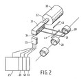
- FIG. 2 One embodiment of an insertion brake which can be used in the loom according to Fig. 1 is shown in Fig. 2.
- a lever 21 in the form of a fork is movable between two fixedly disposed yarn guides 20.
- the lever 21 includes a block 31 on its other side, which is mounted on a shaft 32 of a solenoid motor 33.
- the block 31 includes a magnet 34, which cooperates with a sensor 35.
- a solenoid electric motor is used for driving the movable brake element 21 in this embodiment, it will be apparent that also other types of electric motors can be used, it is even possible to use hydraulic or pneumatic motors.
- a first stroke-limiting stop 41 is disposed on one side of the movable element 21, and a second stop 42 is disposed on the other side thereof.
- the position detection sensor 35 is furthermore connected to a schematically indicated electronic control device 25, which includes the aforesaid programme section 26 of the time-position programme as well as a control module 43 for adjusting the position of the position detection sensor 35 and a function verification module 44 for verifying the correct operation of the brake. Said verification does not comprise the detection of a possible change in the mass of the brake element, however, which might occur in case of fracture of the fork 21.
- the function of the verification module has been extended in such a manner that said module will now also measure the acceleration value of the movable brake element 21, and if the measured acceleration value is higher than or possibly lower than a specified value, a signal will be generated which indicates that the brake is no longer functioning properly.
- the movement of the brake element 21 starts from its position of rest P 0 at point in time t 0 until 1 its braking position P 2 at point in time t 2 .
- the yarn position is indicated by dotted line G. If the mass inertia moment of the brake element 21 is high, i.e. normal, the brake element will follow the line 50 between P 0 and P 2 , which means that its position at point in time t 3 lies at point P 3 . If, in an extreme situation, a part of the arm 21 has broken off for some reason, the mass inertia moment thereof will have decreased considerably.
- the distance between h 0 and h 3 is smaller than the distance between h 0 and h 3 ', which means that the quotient of said distances and the maximum current I max such as occurs in the range between t 0 and t 1 has become larger, and if this quotient exceeds a specified value, the module 44 will generate a specific signal, which either stops the loom or warns the user that something is wrong, so that the user can take adequate action. From the diagram it will be apparent that the range over which measuring takes place lies before the point at which the brake element has reached the yarn G. This means that the measurement is not influenced by the force which the yarn exerts on the brake element.
- the maximum value of the current (I max ) has been used as the control magnitude. It is also possible to use the average value of the current (I avg ) while retaining the same operation and the same advantages.
Landscapes
- Engineering & Computer Science (AREA)
- Textile Engineering (AREA)
- Looms (AREA)
Applications Claiming Priority (2)
| Application Number | Priority Date | Filing Date | Title |
|---|---|---|---|
| NL1017378A NL1017378C2 (nl) | 2001-02-16 | 2001-02-16 | Werkwijze voor de functiebewaking van een inlooprem. |
| NL1017378 | 2001-02-16 |
Publications (2)
| Publication Number | Publication Date |
|---|---|
| EP1233090A1 true EP1233090A1 (de) | 2002-08-21 |
| EP1233090B1 EP1233090B1 (de) | 2006-05-10 |
Family
ID=19772915
Family Applications (1)
| Application Number | Title | Priority Date | Filing Date |
|---|---|---|---|
| EP20020075431 Expired - Lifetime EP1233090B1 (de) | 2001-02-16 | 2002-02-01 | Verfahren zur Überwachung des Betriebes einer Eintragsbremse |
Country Status (3)
| Country | Link |
|---|---|
| EP (1) | EP1233090B1 (de) |
| DE (1) | DE60211233T2 (de) |
| NL (1) | NL1017378C2 (de) |
Cited By (2)
| Publication number | Priority date | Publication date | Assignee | Title |
|---|---|---|---|---|
| WO2019032007A1 (en) * | 2017-08-08 | 2019-02-14 | Iro Aktiebolag | ADJUSTABLE WIRE BRAKE |
| EP3754069A1 (de) * | 2019-06-17 | 2020-12-23 | Vandewiele NV | Schussfadenspannungsvorrichtung und verfahren zum betrieb der schussfadenspannungsvorrichtung |
Citations (3)
| Publication number | Priority date | Publication date | Assignee | Title |
|---|---|---|---|---|
| EP0467059A1 (de) * | 1990-06-11 | 1992-01-22 | NUOVA VAMATEX S.p.A. | Vorrichtung zur Spannungsregulierung und Rückziehen von Schussgarn in Webmaschinen |
| DE4131656A1 (de) * | 1991-09-23 | 1993-03-25 | Iro Ab | Verfahren und webmaschine |
| WO2000044970A1 (en) * | 1999-01-29 | 2000-08-03 | Te Strake B.V. | Loom with an insertion brake |
-
2001
- 2001-02-16 NL NL1017378A patent/NL1017378C2/nl not_active IP Right Cessation
-
2002
- 2002-02-01 EP EP20020075431 patent/EP1233090B1/de not_active Expired - Lifetime
- 2002-02-01 DE DE2002611233 patent/DE60211233T2/de not_active Expired - Fee Related
Patent Citations (3)
| Publication number | Priority date | Publication date | Assignee | Title |
|---|---|---|---|---|
| EP0467059A1 (de) * | 1990-06-11 | 1992-01-22 | NUOVA VAMATEX S.p.A. | Vorrichtung zur Spannungsregulierung und Rückziehen von Schussgarn in Webmaschinen |
| DE4131656A1 (de) * | 1991-09-23 | 1993-03-25 | Iro Ab | Verfahren und webmaschine |
| WO2000044970A1 (en) * | 1999-01-29 | 2000-08-03 | Te Strake B.V. | Loom with an insertion brake |
Cited By (5)
| Publication number | Priority date | Publication date | Assignee | Title |
|---|---|---|---|---|
| WO2019032007A1 (en) * | 2017-08-08 | 2019-02-14 | Iro Aktiebolag | ADJUSTABLE WIRE BRAKE |
| EP3754069A1 (de) * | 2019-06-17 | 2020-12-23 | Vandewiele NV | Schussfadenspannungsvorrichtung und verfahren zum betrieb der schussfadenspannungsvorrichtung |
| WO2020254091A1 (en) * | 2019-06-17 | 2020-12-24 | Vandewiele Nv | Weft thread tensioning device and method of operating a weft thread tensioning device |
| CN113924390A (zh) * | 2019-06-17 | 2022-01-11 | 范德威尔公司 | 纬纱张紧设备和操作纬纱张紧设备的方法 |
| CN113924390B (zh) * | 2019-06-17 | 2023-10-03 | 范德威尔公司 | 纬纱张紧设备和操作纬纱张紧设备的方法 |
Also Published As
| Publication number | Publication date |
|---|---|
| NL1017378C2 (nl) | 2002-08-19 |
| EP1233090B1 (de) | 2006-05-10 |
| DE60211233T2 (de) | 2007-03-08 |
| DE60211233D1 (de) | 2006-06-14 |
Similar Documents
| Publication | Publication Date | Title |
|---|---|---|
| KR100685554B1 (ko) | 삽입브레이크를 갖춘 직기 | |
| JP4546649B2 (ja) | 織機に緯糸を挿入するサイクルを監視する方法 | |
| JP4804703B2 (ja) | 織機へのよこ糸挿入制御方法 | |
| EP0285872B1 (de) | Verfahren zum Kontrollieren und Auswechseln eines Wickelkörpers | |
| EP1233090B1 (de) | Verfahren zur Überwachung des Betriebes einer Eintragsbremse | |
| CN100425752C (zh) | 纱线处理系统 | |
| CN1098943C (zh) | 纱线加工系统和纬纱喂给方法 | |
| US4805276A (en) | Monitoring device for double threads in warp tying machines | |
| KR960012186B1 (ko) | 씨실 삽입상태 검사장치 | |
| EP1775359B1 (de) | Verfahren zur Fehlerdetektion in Schussfadenspulen in Düsenwebmaschinen | |
| EP0240074A2 (de) | Vorrichtung zur Prüfung von Garnen | |
| US5129430A (en) | Weft removal device with measurement of broken yarn piece | |
| CS198183B2 (en) | Method of and apparatus for detecting short picks in shed of weaving looms | |
| CN109943957B (zh) | 喷气式织机的引纬诊断方法 | |
| US5575313A (en) | Apparatus for monitoring a warp yarn movement in a multi-phase weaving machine | |
| US5520224A (en) | Method and weaving machine for monitoring the fell position following weaving operation interuption | |
| EP3348688B1 (de) | Verfahren zur diagnose des schusseintrags in einer luftdüsenwebmaschine und vorrichtung zur diagnose des schusseintrags in einer luftdüsenwebmaschine | |
| CN100432312C (zh) | 控制机械拣选织机的纬纱供给装置上纬纱卷的方法和设备 | |
| EP3505664A1 (de) | Verfahren zur bestimmung der amplitude der rietschwingung für eine luftdüsenwebmaschine | |
| CN1471596A (zh) | 纬线监控装置 | |
| JPH0333820B2 (de) | ||
| JPH0849142A (ja) | たて糸分離装置 | |
| JPH10251942A (ja) | 織機における緯糸異常対処装置 | |
| CN87100360A (zh) | 无梭织机的纬纱处理方法 | |
| CN117512861A (zh) | 用于空气织机的用于自动移除错误纬线的装置以及相关方法 |
Legal Events
| Date | Code | Title | Description |
|---|---|---|---|
| PUAI | Public reference made under article 153(3) epc to a published international application that has entered the european phase |
Free format text: ORIGINAL CODE: 0009012 |
|
| AK | Designated contracting states |
Kind code of ref document: A1 Designated state(s): AT BE CH CY DE DK ES FI FR GB GR IE IT LI LU MC NL PT SE TR |
|
| AX | Request for extension of the european patent |
Free format text: AL;LT;LV;MK;RO;SI |
|
| 17P | Request for examination filed |
Effective date: 20030116 |
|
| AKX | Designation fees paid |
Designated state(s): BE DE IT SE |
|
| RAP1 | Party data changed (applicant data changed or rights of an application transferred) |
Owner name: TE STRAKE TEXTILE B.V. |
|
| RAP1 | Party data changed (applicant data changed or rights of an application transferred) |
Owner name: IRO AKTIEBOLAG |
|
| GRAP | Despatch of communication of intention to grant a patent |
Free format text: ORIGINAL CODE: EPIDOSNIGR1 |
|
| GRAS | Grant fee paid |
Free format text: ORIGINAL CODE: EPIDOSNIGR3 |
|
| GRAA | (expected) grant |
Free format text: ORIGINAL CODE: 0009210 |
|
| AK | Designated contracting states |
Kind code of ref document: B1 Designated state(s): BE DE IT SE |
|
| PG25 | Lapsed in a contracting state [announced via postgrant information from national office to epo] |
Ref country code: IT Free format text: LAPSE BECAUSE OF FAILURE TO SUBMIT A TRANSLATION OF THE DESCRIPTION OR TO PAY THE FEE WITHIN THE PRESCRIBED TIME-LIMIT;WARNING: LAPSES OF ITALIAN PATENTS WITH EFFECTIVE DATE BEFORE 2007 MAY HAVE OCCURRED AT ANY TIME BEFORE 2007. THE CORRECT EFFECTIVE DATE MAY BE DIFFERENT FROM THE ONE RECORDED. Effective date: 20060510 |
|
| REF | Corresponds to: |
Ref document number: 60211233 Country of ref document: DE Date of ref document: 20060614 Kind code of ref document: P |
|
| PG25 | Lapsed in a contracting state [announced via postgrant information from national office to epo] |
Ref country code: SE Free format text: LAPSE BECAUSE OF FAILURE TO SUBMIT A TRANSLATION OF THE DESCRIPTION OR TO PAY THE FEE WITHIN THE PRESCRIBED TIME-LIMIT Effective date: 20060810 |
|
| PLBE | No opposition filed within time limit |
Free format text: ORIGINAL CODE: 0009261 |
|
| STAA | Information on the status of an ep patent application or granted ep patent |
Free format text: STATUS: NO OPPOSITION FILED WITHIN TIME LIMIT |
|
| PGFP | Annual fee paid to national office [announced via postgrant information from national office to epo] |
Ref country code: DE Payment date: 20070328 Year of fee payment: 6 |
|
| 26N | No opposition filed |
Effective date: 20070213 |
|
| PG25 | Lapsed in a contracting state [announced via postgrant information from national office to epo] |
Ref country code: DE Free format text: LAPSE BECAUSE OF NON-PAYMENT OF DUE FEES Effective date: 20080902 |
|
| PGFP | Annual fee paid to national office [announced via postgrant information from national office to epo] |
Ref country code: IT Payment date: 20150223 Year of fee payment: 14 |
|
| PGFP | Annual fee paid to national office [announced via postgrant information from national office to epo] |
Ref country code: BE Payment date: 20150216 Year of fee payment: 14 |
|
| PG25 | Lapsed in a contracting state [announced via postgrant information from national office to epo] |
Ref country code: BE Free format text: LAPSE BECAUSE OF NON-PAYMENT OF DUE FEES Effective date: 20160229 |
|
| PG25 | Lapsed in a contracting state [announced via postgrant information from national office to epo] |
Ref country code: IT Free format text: LAPSE BECAUSE OF NON-PAYMENT OF DUE FEES Effective date: 20160201 |