EP1233104A2 - Procédé et dispositif pour d'écoulement de l'eau blanche - Google Patents
Procédé et dispositif pour d'écoulement de l'eau blanche Download PDFInfo
- Publication number
- EP1233104A2 EP1233104A2 EP02000918A EP02000918A EP1233104A2 EP 1233104 A2 EP1233104 A2 EP 1233104A2 EP 02000918 A EP02000918 A EP 02000918A EP 02000918 A EP02000918 A EP 02000918A EP 1233104 A2 EP1233104 A2 EP 1233104A2
- Authority
- EP
- European Patent Office
- Prior art keywords
- collecting basin
- white water
- channel
- area
- water level
- Prior art date
- Legal status (The legal status is an assumption and is not a legal conclusion. Google has not performed a legal analysis and makes no representation as to the accuracy of the status listed.)
- Ceased
Links
Images
Classifications
-
- D—TEXTILES; PAPER
- D21—PAPER-MAKING; PRODUCTION OF CELLULOSE
- D21F—PAPER-MAKING MACHINES; METHODS OF PRODUCING PAPER THEREON
- D21F1/00—Wet end of machines for making continuous webs of paper
- D21F1/66—Pulp catching, de-watering, or recovering; Re-use of pulp-water
-
- Y—GENERAL TAGGING OF NEW TECHNOLOGICAL DEVELOPMENTS; GENERAL TAGGING OF CROSS-SECTIONAL TECHNOLOGIES SPANNING OVER SEVERAL SECTIONS OF THE IPC; TECHNICAL SUBJECTS COVERED BY FORMER USPC CROSS-REFERENCE ART COLLECTIONS [XRACs] AND DIGESTS
- Y10—TECHNICAL SUBJECTS COVERED BY FORMER USPC
- Y10S—TECHNICAL SUBJECTS COVERED BY FORMER USPC CROSS-REFERENCE ART COLLECTIONS [XRACs] AND DIGESTS
- Y10S162/00—Paper making and fiber liberation
- Y10S162/07—Water collectors, e.g. save-alls
Definitions
- the invention relates to a method and a device for removing the within the loop of a circulating dewatering screen of a former a paper machine of white water.
- Methods and devices of this type are, for example, from EP 0 258 918 B1, US 4,895,623, AT-PS 293,855 and US 2,893,486.
- the aim of the invention is to provide an improved method and an improved device to create the type mentioned, in which the aforementioned Disadvantages are eliminated.
- this object is achieved by a method for removal inside the loop of a circulating dewatering screen of a former, in particular a twin wire former, a paper machine White water, in which the white water is arranged by a within the loop Collection basin collected, the collected white water by suction the area above the collecting basin still within the sieve loop separated from the air and the white water over at least one itself adjoining the reservoir, below the water level Canal is removed from the collection basin.
- the amount of white water generated is already within the wire loop or in the sieve ship so far from the air that they are completely Pipeline filled with white water discharged from the machine area can be.
- the space previously required outside the machine frame for gutter laying and the installation of separators significantly reduced.
- the possibilities for standard arrangements are correspondingly created because of the risk of a possible collision with the building is reduced to a minimum.
- the previously required separators next to the paper machine can be omitted.
- there is a simpler stool since no breakthroughs in the stool are required for white water drainage are.
- the largest possible collection basin is used.
- the collecting basin expediently extends to the two sides of the chair on the leader and drive side and is preferably through these two Chair sides and corresponding cross members formed.
- the method of collecting basins is at least essentially airtight Provide hood and this hood evacuated by a suction system separate the air from the white water collected in the collection basin.
- a hood is expediently used, whose cross-machine direction extending sides are free of openings. The only openings to the atmosphere are therefore those on the drainage elements in question required openings on the end faces of the paper machine.
- the white water can be stowed in the collecting basin, so that the above the water level in the collecting basin is maintained and the white water flows out of the screen area below this water level can.
- the flow speed of the white water in the suction area or in the area the collecting basin is advantageously less than about 1 m / s. she can in particular less than about 0.5 m / s and preferably less than about 0.2 m / s his. With such a relatively low speed, the result is better Venting degrees.
- the length of the suction area viewed in the machine direction is expedient greater than about 0.5 m. In particular, it can be larger than approximately 1 m and preferably be greater than about 2 m.
- the length of the suction area viewed in the machine running direction can in particular be at least substantially the same as that viewed in the machine direction Extension of the collection basin.
- the process is the upward canal adjoining the collecting basin open or closed, the water level in this preferably at least channel completely filled with white water is lower than that Water level in the pool.
- the white water can be discharged through the canal adjoining the collecting basin are led out of the side of the screen area. This can be done laterally outside the sieve area on this channel e.g. at least one pipe be connected via which the white water, in particular one outside the Screen area and the former area arranged screen water tank supplied becomes. The white water can then again via this white water tank be fed into the process.
- the clear height or the inner diameter of the at least essentially completely pipeline filled with white water at least essentially equal to the inside height of the pool subsequent channel.
- the water level in the white water tank is higher than the water level in the pipeline and in the channel adjoining the collecting basin.
- the white water is on the side outside of the sieve area at the one with the collecting basin connected channel connected at least one preferably open channel at the top, through which the white water is outside the sieve area and Forming area arranged white water tank is supplied. About this White water tank, the white water can be returned to the process.
- the water level is in the channel adjoining the collection basin is lower than the water levels in the collecting basin and the white water tank.
- the water level in the Collection tank is higher than the water level in the white water tank and the water level in this white water tank is higher than the water level in the canal adjoining the collecting basin.
- the water level in the white water tank is less than the water level in the reservoir, where the height difference in particular greater than 100 mm and preferably greater than Is 300 mm.
- the flow velocity in the channel is greater than 1.2 m / s and preferably greater than 2.4 m / s, the cross-sectional area thereof being in particular less than 2 m 2 and preferably less than 1 m 2 .
- the flow velocity in the adjoining the collecting basin Canal, through which the white water is first moved laterally out of the Screen area can be brought out, in particular by the choice of Difference between the water level in the reservoir and the water level be set in the white water tank. Accordingly, any White water quantities are discharged, which is the case with the devices customary to date was not possible with a free slope. Because the flow rate in itself the collecting basin connecting channel is relatively large, arise for the side openings relatively small cross-sectional areas.
- the device according to the invention accordingly comprises a within the sieve loop arranged collection basin, which with at least one at least in essential airtight hood, evacuable by a suction system is to get the collected white water still within the wire loop of the Separating air, and at least one adjoining the collecting basin, channel below the water level to drain the white water from the pool.
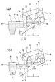
- Figures 1 and 2 show two purely exemplary embodiments of a device 10 for removing the inside the loop of a circulating drainage sieve 12 of a former, in particular a twin wire former, a paper machine of white water.
- a collecting basin 14 is arranged within the wire loop, in the white water 16 is collected, in particular with drainage elements 18 provided areas.
- the collection basin 14 has an at least substantially airtight hood 20 provided.
- This hood 20 can be evacuated by a suction system 22 in order to Separate collected white water from the air within the sieve loop.
- the collecting basin 14 is followed by a channel 24 lying overall below the water level N 1 of this collecting basin 14, via which the white water can be discharged generally transversely to the machine or wire running direction I.
- the collecting basin 14 has a large surface area and can extend up to the two sides of the chair on the driver and drive side of the paper machine or can be limited laterally by these sides of the chair.
- the collecting basin 14 can thus be formed in particular by these sides of the chair and corresponding cross members. As can be seen from FIGS. 1 and 2, the bottom of the collecting container 14 drops towards the channel 24.
- the white water is accumulated in the collecting basin 14 in order to maintain the water level N 1 in the collecting basin 14 above the channel 24.
- the storage wall 26 in question ultimately also delimits the collecting container 14 from the channel 24, which is connected to the collecting container 14 via the free area below the storage wall 26.
- the channel 24 can be open or closed at the top. It is essential that the water level N 2 in this channel 24 is lower than the water level or the water level N 1 in the collecting container 14.
- the sides of the hood 20 which extend transversely to the machine direction I are preferably free of openings.
- the only openings to the atmosphere are therefore the openings on the drainage elements required Front of the machine.
- the flow velocity v s of the white water in the suction area or in the area of the collecting basin 14 is preferably less than about 1 m / s, as a result of which a better degree of ventilation is achieved. In particular, it can be less than about 0.5 m / s and preferably less than about 0.2 m / s.
- the length LE of the suction area considered in machine direction I is expediently larger than about 0.5 m. In particular, it can be larger than about 1 m and preferably greater than about 2 m. As with the two figures 1 and 2 can be seen, this can be viewed in the machine running direction I. Length LE of the suction area is at least substantially the same as that in the machine direction I considered extension of the collection basin 14.
- the channel 24 extends laterally out of the sieve area out.
- a channel 28 which is open at the top, for example, is connected to the channel 14 connected to the collecting basin 14 laterally outside the screening area.
- the white water is fed via this channel 28 to a white water container 30 arranged outside the sieve area and the former area.
- the water level N 4 in the channel 28 is equal to the water level N 3 in the white water tank 30.
- the white water is the White water tank 30 supplied via this pipe 32.
- the pipeline 32 of the embodiment according to FIG. 2 is completely filled with white water.
- the clear height or the inner diameter of this pipeline 32 is at least substantially equal to the clear height of the channel 24 adjoining the collecting basin 14.
- the water level N 3 in the white water tank 30 is higher than the water level in the pipeline 32 and the water level N 2 in the channel 24 adjoining the collecting basin 14.
- the water level N 2 in the channel 24 adjoining the collecting basin 14 is therefore lower than the water levels N 1 , N 3 in the collecting basin 14 and the white water tank 30. Furthermore, the water level N 1 in the collecting basin 14 is higher than that Water level N 3 in the white water tank 30.
- N 2 can, for example, also be higher than N 3 , or, for example when the channel 24 is closed, also higher than N 1 .
Landscapes
- Paper (AREA)
Applications Claiming Priority (2)
| Application Number | Priority Date | Filing Date | Title |
|---|---|---|---|
| DE10107328A DE10107328A1 (de) | 2001-02-16 | 2001-02-16 | Verfahren und Vorrichtung zum Abführen von Siebwasser |
| DE10107328 | 2001-02-16 |
Publications (2)
| Publication Number | Publication Date |
|---|---|
| EP1233104A2 true EP1233104A2 (fr) | 2002-08-21 |
| EP1233104A3 EP1233104A3 (fr) | 2003-12-10 |
Family
ID=7674316
Family Applications (1)
| Application Number | Title | Priority Date | Filing Date |
|---|---|---|---|
| EP02000918A Ceased EP1233104A3 (fr) | 2001-02-16 | 2002-01-16 | Procédé et dispositif pour d'écoulement de l'eau blanche |
Country Status (3)
| Country | Link |
|---|---|
| US (1) | US6638394B2 (fr) |
| EP (1) | EP1233104A3 (fr) |
| DE (1) | DE10107328A1 (fr) |
Cited By (2)
| Publication number | Priority date | Publication date | Assignee | Title |
|---|---|---|---|---|
| WO2010091915A1 (fr) | 2009-02-12 | 2010-08-19 | Voith Patent Gmbh | Formeur à double toile |
| EP3577426A4 (fr) * | 2017-02-02 | 2020-12-23 | Runtech Systems Oy | Appareil de mesure de la déshydratation d'une machine à papier à différents points de l'extrémité humide et son procédé de réalisation |
Families Citing this family (4)
| Publication number | Priority date | Publication date | Assignee | Title |
|---|---|---|---|---|
| DE50014738D1 (de) * | 2000-01-14 | 2007-12-06 | Voith Patent Gmbh | Pressenanordnung |
| DE10356576A1 (de) * | 2003-12-04 | 2005-07-07 | Voith Paper Patent Gmbh | Verfahren zum Führen von an einer Papiermaschine offen anfallendem Siebwasser |
| US20050219939A1 (en) * | 2004-04-05 | 2005-10-06 | Mcneilus Truck And Manufacturing, Inc. | Concrete batching pre-mixer and method |
| US7320539B2 (en) * | 2004-04-05 | 2008-01-22 | Mcneilus Truck And Manufacturing, Inc. | Concrete batching facility and method |
Family Cites Families (25)
| Publication number | Priority date | Publication date | Assignee | Title |
|---|---|---|---|---|
| US2893486A (en) * | 1956-02-27 | 1959-07-07 | Crown Zellerbach Corp | Fourdrinier paper making machine |
| NL295754A (fr) * | 1963-07-24 | |||
| US3266975A (en) * | 1963-08-02 | 1966-08-16 | Beloit Corp | Automatically controlled pressure flow suction flatbox for paper-making machine |
| US3997390A (en) * | 1965-08-14 | 1976-12-14 | Valmet Oy | Twin-wire paper machine and method for operating the same |
| US3507746A (en) * | 1967-03-22 | 1970-04-21 | Texas Instruments Inc | Automatic vacuum suction box in papermaking |
| FR1582914A (fr) * | 1967-08-02 | 1969-10-10 | ||
| US3539448A (en) * | 1968-04-19 | 1970-11-10 | Kasimir Lopas | Suction box for papermaking apparatus |
| JPS4920409A (fr) * | 1972-06-26 | 1974-02-22 | ||
| US3846233A (en) * | 1972-09-11 | 1974-11-05 | Valmet Oy | Papermaking machine having a single wire run and a double wire run over a downwardly curving dewatering box |
| FI51973C (fi) * | 1973-03-23 | 1979-01-05 | Valmet Oy | Pappersmaskin med tvao viror |
| US3884756A (en) * | 1973-09-27 | 1975-05-20 | Beloit Corp | Multi-ply linerboard machine with vertical and horizontal forming runs |
| US3951736A (en) * | 1974-12-30 | 1976-04-20 | Tadashi Kobayashi | Single-layer and multi-layer paper making apparatus |
| FI761030A7 (fr) * | 1976-04-14 | 1977-10-15 | Valmet Oy | |
| FI64958C (fi) * | 1978-02-07 | 1984-02-10 | Valmet Oy | Banformare med dubbelvira foer en pappersmaskin |
| SE410482B (sv) * | 1978-02-15 | 1979-10-15 | Karlstad Mekaniska Ab | Forfarande och anordning vid en dubbelviraformare |
| US4167441A (en) * | 1978-05-03 | 1979-09-11 | Sandy Hill Corporation | Papermaking machine |
| US4267017A (en) * | 1980-01-09 | 1981-05-12 | Beloit Corporation | Drainage roof for twin wire roll former |
| SE421939B (sv) * | 1980-06-05 | 1982-02-08 | Karlstad Mekaniska Ab | Forfarande for bakvattenhantering |
| SE428811B (sv) * | 1981-12-03 | 1983-07-25 | Karlstad Mekaniska Ab | Forfarande och anordning for framstellning av en flerskiktad pappersbana |
| US4478615A (en) * | 1982-09-29 | 1984-10-23 | Clark & Vicario Corporation | Deaerated liquid stock supply |
| IT1201808B (it) * | 1986-09-05 | 1989-02-02 | Awe Anti Wear Eng Srl | Procedimento di disidratazione della pasta per carta e contemporanea formazione del foglio in un sistema a doppia tela ed impianto adottante tale procedimento |
| US5468348A (en) * | 1990-07-10 | 1995-11-21 | Beloit Technologies, Inc. | Multi-ply web former and method |
| US5202000A (en) * | 1991-09-30 | 1993-04-13 | Beloit Technologies, Inc. | Saveall apparatus for a twin-wire former |
| US5851357A (en) * | 1997-03-03 | 1998-12-22 | Valmet, Inc. | Combination saveall and blowbox system |
| ATE258249T1 (de) * | 1998-06-18 | 2004-02-15 | Astenjohnson Inc | Vorrichtung und verfahren zur erzeugung von stoffturbulenz im blattbildner einer langsiebpapiermaschine |
-
2001
- 2001-02-16 DE DE10107328A patent/DE10107328A1/de not_active Withdrawn
-
2002
- 2002-01-16 EP EP02000918A patent/EP1233104A3/fr not_active Ceased
- 2002-02-15 US US10/077,253 patent/US6638394B2/en not_active Expired - Fee Related
Cited By (3)
| Publication number | Priority date | Publication date | Assignee | Title |
|---|---|---|---|---|
| WO2010091915A1 (fr) | 2009-02-12 | 2010-08-19 | Voith Patent Gmbh | Formeur à double toile |
| DE102009000803A1 (de) | 2009-02-12 | 2010-08-19 | Voith Patent Gmbh | Doppelsiebformer |
| EP3577426A4 (fr) * | 2017-02-02 | 2020-12-23 | Runtech Systems Oy | Appareil de mesure de la déshydratation d'une machine à papier à différents points de l'extrémité humide et son procédé de réalisation |
Also Published As
| Publication number | Publication date |
|---|---|
| US6638394B2 (en) | 2003-10-28 |
| DE10107328A1 (de) | 2002-08-29 |
| US20020112837A1 (en) | 2002-08-22 |
| EP1233104A3 (fr) | 2003-12-10 |
Similar Documents
| Publication | Publication Date | Title |
|---|---|---|
| WO2004013468A1 (fr) | Separateur d'huile destine a la separation de l'huile du gaz de ventilation du carter de vilbrequin d'une machine a combustion interne | |
| EP0429593B1 (fr) | Separateur de liquides legers | |
| DE3538843A1 (de) | Vorrichtung zur kontinuierlichen trennung von fluessigen gemischen | |
| EP0014448B1 (fr) | Procédé et dispositif pour le désencrage de suspensions de matières fibreuses | |
| DE2944207A1 (de) | Verfahren zum abscheiden von feststoffen aus einer fluessigkeit und abscheider zur durchfuehrung dieses verfahrens | |
| DE1461079A1 (de) | Verfahren und Vorrichtung zur im wesentlichen konstanten Zufuehrung einer gereinigten und entluefteten Papierstoffsuspension | |
| EP0201072B1 (fr) | Separateur de liquides légers | |
| EP1233104A2 (fr) | Procédé et dispositif pour d'écoulement de l'eau blanche | |
| EP0894891B1 (fr) | Procédé et appareil pour éliminer les matières solides d'une suspension de fibres aqueuse | |
| DE19823053C1 (de) | Verfahren zur Flotation von Störstoffen aus einer wässrigen Faserstoffsuspension | |
| DE3139304A1 (de) | Vorrichtung fuer regenfallrohre | |
| EP1028192B1 (fr) | Procédé pour enlever les matières solides d'une suspension de pâte à papier aqueuse | |
| DE602004010139T2 (de) | Verfahren und vorrichtung zur trennung von materialströmen | |
| EP1001078B1 (fr) | Méthode et dispositif pour la séparation des particules d'une suspension aqueuse de fibres à papier | |
| DE3238600C2 (fr) | ||
| DE2364208A1 (de) | Verfahren und vorrichtung zur herstellung einer faserbahn | |
| DE2837566C2 (de) | Vorrichtung zur Bildung einer Bahn auf einem Sieb aus einer Fasersuspension | |
| EP1416086A2 (fr) | Procédé et dispositif de flottation pour élimination des contaminants d'une suspension aqueuse de fibres | |
| DE20000599U1 (de) | Wasserabführeinrichtung | |
| DE19545633C1 (de) | Verfahren und Vorrichtung zur Abscheidung von Flüssigkeiten aus Schlamm | |
| EP1001079B1 (fr) | Méthode et dispositif pour la séparation des particules d'une suspension aqueuse de fibres à papier | |
| DE60125358T2 (de) | Vorrichtung für einen siebwasserabführkanal | |
| DE3930226C2 (fr) | ||
| EP1538258B1 (fr) | Procédé pour guider de l'eau blanche d'une machine à papier | |
| DE1761496C (de) | Vorrichtung zum fortlaufenden Zuführen einer gereinigten und entlüfteten Papierstoffsuspension zu einer Papiermaschine |
Legal Events
| Date | Code | Title | Description |
|---|---|---|---|
| PUAI | Public reference made under article 153(3) epc to a published international application that has entered the european phase |
Free format text: ORIGINAL CODE: 0009012 |
|
| AK | Designated contracting states |
Kind code of ref document: A2 Designated state(s): AT BE CH CY DE DK ES FI FR GB GR IE IT LI LU MC NL PT SE TR |
|
| AX | Request for extension of the european patent |
Free format text: AL;LT;LV;MK;RO;SI |
|
| PUAL | Search report despatched |
Free format text: ORIGINAL CODE: 0009013 |
|
| AK | Designated contracting states |
Kind code of ref document: A3 Designated state(s): AT BE CH CY DE DK ES FI FR GB GR IE IT LI LU MC NL PT SE TR |
|
| AX | Request for extension of the european patent |
Extension state: AL LT LV MK RO SI |
|
| 17P | Request for examination filed |
Effective date: 20040611 |
|
| AKX | Designation fees paid |
Designated state(s): AT DE FI IT SE |
|
| RAP1 | Party data changed (applicant data changed or rights of an application transferred) |
Owner name: VOITH PATENT GMBH |
|
| STAA | Information on the status of an ep patent application or granted ep patent |
Free format text: STATUS: THE APPLICATION HAS BEEN REFUSED |
|
| 18R | Application refused |
Effective date: 20060706 |