EP1233127A1 - Sicherheitsschloss mit erhöht Selektivität - Google Patents
Sicherheitsschloss mit erhöht Selektivität Download PDFInfo
- Publication number
- EP1233127A1 EP1233127A1 EP02290407A EP02290407A EP1233127A1 EP 1233127 A1 EP1233127 A1 EP 1233127A1 EP 02290407 A EP02290407 A EP 02290407A EP 02290407 A EP02290407 A EP 02290407A EP 1233127 A1 EP1233127 A1 EP 1233127A1
- Authority
- EP
- European Patent Office
- Prior art keywords
- key
- flap
- longitudinal axis
- axis
- barrel
- Prior art date
- Legal status (The legal status is an assumption and is not a legal conclusion. Google has not performed a legal analysis and makes no representation as to the accuracy of the status listed.)
- Granted
Links
- 238000013519 translation Methods 0.000 claims abstract description 12
- 238000013475 authorization Methods 0.000 claims description 10
- 230000002093 peripheral effect Effects 0.000 claims description 3
- 230000000295 complement effect Effects 0.000 claims 1
- 230000000873 masking effect Effects 0.000 abstract 1
- 235000021183 entrée Nutrition 0.000 description 4
- 238000012360 testing method Methods 0.000 description 3
- 230000004308 accommodation Effects 0.000 description 2
- 230000000694 effects Effects 0.000 description 2
- 230000012010 growth Effects 0.000 description 2
- 238000003780 insertion Methods 0.000 description 2
- 230000037431 insertion Effects 0.000 description 2
- 239000000523 sample Substances 0.000 description 2
- 238000011161 development Methods 0.000 description 1
- 238000006073 displacement reaction Methods 0.000 description 1
- 238000003475 lamination Methods 0.000 description 1
- 230000035515 penetration Effects 0.000 description 1
Images


Classifications
-
- E—FIXED CONSTRUCTIONS
- E05—LOCKS; KEYS; WINDOW OR DOOR FITTINGS; SAFES
- E05B—LOCKS; ACCESSORIES THEREFOR; HANDCUFFS
- E05B27/00—Cylinder locks or other locks with tumbler pins or balls that are set by pushing the key in
- E05B27/0042—Cylinder locks or other locks with tumbler pins or balls that are set by pushing the key in with additional key identifying function, e.g. with use of additional key operated rotor-blocking elements, not of split pin tumbler type
-
- E—FIXED CONSTRUCTIONS
- E05—LOCKS; KEYS; WINDOW OR DOOR FITTINGS; SAFES
- E05B—LOCKS; ACCESSORIES THEREFOR; HANDCUFFS
- E05B17/00—Accessories in connection with locks
- E05B17/14—Closures or guards for keyholes
- E05B17/18—Closures or guards for keyholes shaped as lids or slides
- E05B17/185—Closures or guards for keyholes shaped as lids or slides pivoting about an axis perpendicular to the lock face
-
- E—FIXED CONSTRUCTIONS
- E05—LOCKS; KEYS; WINDOW OR DOOR FITTINGS; SAFES
- E05B—LOCKS; ACCESSORIES THEREFOR; HANDCUFFS
- E05B19/00—Keys; Accessories therefor
- E05B19/0017—Key profiles
-
- E—FIXED CONSTRUCTIONS
- E05—LOCKS; KEYS; WINDOW OR DOOR FITTINGS; SAFES
- E05B—LOCKS; ACCESSORIES THEREFOR; HANDCUFFS
- E05B29/00—Cylinder locks and other locks with plate tumblers which are set by pushing the key in
- E05B29/0013—Cylinder locks and other locks with plate tumblers which are set by pushing the key in with rotating plate tumblers
-
- E—FIXED CONSTRUCTIONS
- E05—LOCKS; KEYS; WINDOW OR DOOR FITTINGS; SAFES
- E05B—LOCKS; ACCESSORIES THEREFOR; HANDCUFFS
- E05B17/00—Accessories in connection with locks
- E05B17/14—Closures or guards for keyholes
- E05B17/18—Closures or guards for keyholes shaped as lids or slides
Definitions
- the invention relates generally to the field security locks.
- the invention concerns a security lock, comprising an essentially cylindrical, elongated body along a longitudinal axis, a barrel having a key entry and mounted in the body rotating around from the longitudinal axis and in translation along the axis longitudinal in a direction of introduction of the key, from a rest position to which it is elastically stressed, at least a first component for concealing the key entry, mounted movably in the body in a plane transverse to the longitudinal axis, and elastically returned to a rest position by a centripetal elastic force, and an internal groove practiced in an internal periphery of the body, the first flap being selectively moved from its position rest to an authorization position by any key adapted presenting, along the plane transverse to the axis longitudinal, a thickness section adapted to the lock and for which the first flap escapes the internal groove, and the first flap being selectively moved from its rest position to a first position shifted by any unsuitable key or false key having, along the plane transverse to
- the present invention has precisely for the purpose, according to a first of its aspects, of propose a lock for increased selectivity.
- the lock of the invention is essentially characterized in that the first flap has a second external edge element by which it is engaged in the internal throat at least when placed in a position within a range of intermediate positions between its position of rest and its authorization position, and in that the first flap is rotatably mounted on the barrel around a secondary axis parallel to the longitudinal axis and offset relative to it towards a periphery of the barrel, this secondary axis being arranged in an axial plane passing between the first and second edge elements external of the first shutter.
- test bodies described in these documents are not blackout shutters moved by the key itself, but tilting levers each of which is driven by a pointed probe pressing locally on the key.
- the first component is engaged in the internal groove by its second external edge element when in its rest position and any position intermediate between its rest position and its position authorization.
- the first part includes example a peduncle button forming a pivot, centered on the secondary axis, and received in additional accommodation of the barrel.
- the first component has a heel with the first edge element external and a point carrying the second edge element external, that the heel has an internal edge arranged on the key entry and selectively moved by a key section, depending on the thickness, the shape, and / or position of this section, and that the secondary axis is placed in the tip of the first shutter.
- the internal edge of the first flap can be chamfered to facilitate insertion and removal of the key.
- the lock the invention comprises a second part identical to the first component, the first and second components adopting respective rest positions deduced from one of the other by rotation around the longitudinal axis.
- This lock can also include a bracelet pre-stressed spring in extension and engaged in respective external peripheral grooves of the first and second flaps to exert the centripetal elastic force on these two strands.
- the heel of each flap and the tip of the other flap can interpenetrate when these components are in their rest position.
- the invention also relates to a key or a key blank which not only can be used for actuation of a lock according to the invention, such as previously defined, but which has a structure which makes it inherently difficult to reproduce by any unauthorized person.
- Such a key or key blank which includes, in a manner known per se, a rod which can be operated by hand and oriented along a longitudinal axis, and a bit carried by one end of the rod to activate the lock, the bit having, in a transverse plane at the longitudinal axis, a reduced section at least partially drawn by a groove which is dug there, is essentially characterized in that the section reduced is asymmetrical compared to any plane parallel to the longitudinal axis.
- the reduced section admits the axis longitudinal as axis of rotation symmetry.
- This reduced section can in particular extend the along an average course and present, perpendicular to this average course, a thickness substantially constant.
- the average route advantageously has a sinuous shape, indifferently made up of curves or zigzags.
- the key or key blank according to the invention is to preferably carried out at least in part by stamping.
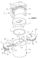
- the inventive security lock includes essentially, in a known manner, a cylindrical body 1, a barrel 2, and one or more components such as 3 and 4.
- the body 1 of generally cylindrical shape, is elongated along a longitudinal axis X and closed by a face 10 in which an orifice 12 is drilled allowing the introduction of a key, such as key 5 illustrated in Figure 5.
- this body 1 carries, in its periphery internal 100, an internal groove 11.
- Barrel 2 is mounted in translation in the body 1 along the X axis, in a direction D of key 5, and against a force elastic which reminds him in a rest position for which it rests on the face 71 of a lining 7, this lining pressing itself against the face 10 of the body 1.
- Barrel 2 which has a key entry 20, is also rotatably mounted in the body 1 around the longitudinal axis X.
- Each of the components such as 3 and 4 allows to hide the key entry 20, is movably mounted in the body 1 in a plane Pt transverse to the longitudinal axis X, and is resiliently returned to a rest position by a centripetal elastic force, i.e. a force which urges each flap towards the longitudinal axis X.
- the gasket 7, arranged between the barrel 2 and the face 10 of body 1, is itself pierced with a passage 70 for key 5.
- Each of the components 3 and 4 may, in known manner, adopt at least three positions, namely the position of previously mentioned rest, in which this shutter closes at least partially the key entry 20, a position authorization in which this component escapes the throat internal 11 and authorizes the translation of the barrel 2 by relative to the body 1, and a first offset position, in which this flap falls into the internal groove 11 and prohibits the translation of barrel 2 relative to the body 1.
- each component such as 3 and 4 is moved from its rest position to its position authorization by any key suitable for the lock, that is to say by a key presenting, according to the plane Pt transverse to the longitudinal axis X ( Figure 2), a section 50 of maximum thickness E suitable for lock considered (figure 4).
- Each flap such as 3 and 4 is moved from its rest position towards its first position offset by any geometry key unsuitable for the lock and any false key, and in particular by a key or substitute for key presenting, along the plane Pt transverse to the axis longitudinal X, a section 50 of thickness greater than thickness E suitable for the lock in question.
- each component such that 3 and 4 falls into the internal groove 11 by a first outer edge element, such as 31 and 41, of this flap, and prohibits a translation of the barrel 2 by relation to the body 1.
- each shutter has a second outer edge element, such as 32 and 42, by which it is engaged in the internal groove 11 at less when placed in a position within a range of intermediate positions between its position rest and its authorization position.
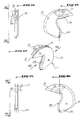
- each component 3, 4 is engaged in the internal groove 11 by its second external edge element 32, 42 when it occupies its rest position ( Figures 10 and 11) and any intermediate position between its position rest and its authorization position.
- each component 3, 4 is rotatably mounted on the barrel 2 about an axis secondary XX parallel to the longitudinal axis X of the body 1.
- Each secondary axis XX is offset from the longitudinal axis X of the body 1 towards the periphery 200 of the barrel 2, and is arranged in an axial plane Pa (FIG. 6) which passes between the first and second edge elements external, such as 31, 32 and 41, 42, of each flap 3 and 4.
- each part 3, 4 comprises by example a peduncle button, such as 33, 43, forming pivot, centered on the corresponding secondary axis XX, and received in corresponding additional accommodation 23 from barrel 2.
- a peduncle button such as 33, 43, forming pivot, centered on the corresponding secondary axis XX, and received in corresponding additional accommodation 23 from barrel 2.
- each flap such as 3 and 4 has a heel such than 34 and 44, and a point such as 35 and 45, the axis secondary XX of each flap 3 and 4 being arranged in the tip 35, 45 of this component.
- each flap 3, 4 carries the first external edge element 31, 41 of this flap, while the tip 35, 45 of this same flap carries the second corresponding outer edge element 32, 42.
- Each heel 34, 44 also has an edge internal, such as 340 and 440, which is arranged on the entrance of key 20 and which is moved by the reduced section 50 of key 5, depending on thickness, shape and / or the position of this section 50.
- edge internal 340, 440 of each component 3, 4 is advantageously chamfered to facilitate insertion and removal of the key 5.
- the shutters 3 and 4 are preferably two in number and adopt rest positions which are deduced from each other by a 180 degree rotation around the longitudinal axis X.
- centripetal force which elastically urges flaps 3 and 4 towards their rest position is for example exerted by a spring bracelet 6 ( Figures 1 and 7 in particular), pre-stressed in extension, and engaged in respective external peripheral grooves 36 and 46 of these parts 3 and 4.
- Each flap 3, 4 preferably has ( Figures 1, 11 and 15) a growth such as 341 and 441 formed on its heel 34, 44, and a counterbore such as 351 and 451 formed in its tip, so that in the position of rest of these flaps, the heel 34 and 44 of each flap and the point 45 and 35 of the other flap interpenetrate, by penetration of one of the growths in that of the two the adjacent laminations.
- a key 5 (figure 5) or a blank key 500 ( Figures 2 and 3) usable for actuating a lock as described above comprises, so known, a rod 51 which can be operated by hand and oriented, in operation, along the longitudinal axis X of the lock, and a bit 52 carried by one end 510 of the rod 51 for actuating the lock.
- bit 52 has ( Figure 2), in the plane Pt transverse to the axis longitudinal X, a reduced section at least 50 partially drawn by a groove 53 which is there dug.
- the reduced section 50 is asymmetrical with respect to any plane parallel to the axis longitudinal X.
- the reduced section 50 admits the axis longitudinal X as axis of rotation symmetry, and is in this case invariant by rotation of 180 degrees around the X axis.
- the reduced section 50 can extend along a medium course M and can also, without limitation, present, perpendicular to this average path M, a thickness E substantially constant, regardless of the width global L presented in this section 50.
- the average course M can develop following a rounded or zigzag curve, but has preferably a curvy shape in all cases of Fig.
- the key or key blank thus defined is advantageously carried out by stamping, at least in part.
- the selectivity of the lock of the invention is not only increased by the establishment of a lower thickness limit in addition to the limit superior: it is also by a form effect, as can be understood from Figure 4, assumed represent the reduced section 50 of a key or blank adapted to the lock in question.
- the stroke made by flaps 3 and 4 from their rest position under the effect of the introduction of this other key or draft will be oversized by contact with the flaps in zones 501 if the average distance M of the section of this other key or draft is less curve as shown in Figure 4, and will be oversized by contact with the flaps in zones 502 if the average path M of the section of this other key or blank is more curved than that of figure 4.
Landscapes
- Physics & Mathematics (AREA)
- Electromagnetism (AREA)
- Lock And Its Accessories (AREA)
- Acyclic And Carbocyclic Compounds In Medicinal Compositions (AREA)
- Rigid Containers With Two Or More Constituent Elements (AREA)
- Preventing Unauthorised Actuation Of Valves (AREA)
- Medicinal Preparation (AREA)
- Transition And Organic Metals Composition Catalysts For Addition Polymerization (AREA)
- Footwear And Its Accessory, Manufacturing Method And Apparatuses (AREA)
- Gloves (AREA)
Priority Applications (1)
| Application Number | Priority Date | Filing Date | Title |
|---|---|---|---|
| EP05027061A EP1637672B1 (de) | 2001-02-20 | 2002-02-20 | Schlüssel oder Schlüsselrohling |
Applications Claiming Priority (2)
| Application Number | Priority Date | Filing Date | Title |
|---|---|---|---|
| FR0102268A FR2821106B1 (fr) | 2001-02-20 | 2001-02-20 | Serrure de surete a selectivite accrue et clef correspondante |
| FR0102268 | 2001-02-20 |
Related Child Applications (1)
| Application Number | Title | Priority Date | Filing Date |
|---|---|---|---|
| EP05027061A Division EP1637672B1 (de) | 2001-02-20 | 2002-02-20 | Schlüssel oder Schlüsselrohling |
Publications (2)
| Publication Number | Publication Date |
|---|---|
| EP1233127A1 true EP1233127A1 (de) | 2002-08-21 |
| EP1233127B1 EP1233127B1 (de) | 2006-10-18 |
Family
ID=8860215
Family Applications (2)
| Application Number | Title | Priority Date | Filing Date |
|---|---|---|---|
| EP05027061A Expired - Lifetime EP1637672B1 (de) | 2001-02-20 | 2002-02-20 | Schlüssel oder Schlüsselrohling |
| EP02290407A Expired - Lifetime EP1233127B1 (de) | 2001-02-20 | 2002-02-20 | Sicherheitsschloss mit erhöht Selektivität |
Family Applications Before (1)
| Application Number | Title | Priority Date | Filing Date |
|---|---|---|---|
| EP05027061A Expired - Lifetime EP1637672B1 (de) | 2001-02-20 | 2002-02-20 | Schlüssel oder Schlüsselrohling |
Country Status (8)
| Country | Link |
|---|---|
| EP (2) | EP1637672B1 (de) |
| AT (2) | ATE366857T1 (de) |
| CY (1) | CY1108613T1 (de) |
| DE (2) | DE60221165T2 (de) |
| DK (1) | DK1637672T3 (de) |
| ES (2) | ES2287859T3 (de) |
| FR (1) | FR2821106B1 (de) |
| PT (2) | PT1637672E (de) |
Cited By (2)
| Publication number | Priority date | Publication date | Assignee | Title |
|---|---|---|---|---|
| WO2014072570A1 (en) * | 2012-11-07 | 2014-05-15 | Abloy Oy | Disc tumbler cylinder lock and key combination |
| FR3050222A1 (fr) * | 2016-04-18 | 2017-10-20 | Assa Abloy Cote Picarde | Serrure de surete |
Families Citing this family (3)
| Publication number | Priority date | Publication date | Assignee | Title |
|---|---|---|---|---|
| WO2018041277A1 (en) * | 2016-09-01 | 2018-03-08 | UrbanAlps Czech s.r.o. | A key for controlling a lock with a cylindrical plug and a lock for validating this key |
| EP4190999A1 (de) * | 2021-12-03 | 2023-06-07 | dormakaba Schweiz AG | Sperrvorrichtung mit einem stator, mit einem rotor und mit einer abziehschutzvorrichtung |
| IT202400004228A1 (it) * | 2024-02-28 | 2025-08-28 | Pier Luigi Oliana | Disco di protezione per serrature. |
Citations (3)
| Publication number | Priority date | Publication date | Assignee | Title |
|---|---|---|---|---|
| FR2552146A1 (fr) * | 1983-09-16 | 1985-03-22 | Fichet Bauche | Serrure de surete |
| EP0633373A1 (de) * | 1993-07-08 | 1995-01-11 | Aug. Winkhaus GmbH & Co. KG | Schliesszylinder mit Schlüssel, Gruppen solcher Schliesszylinder, ein Schlüssel für einen solchen Schliesszylinder und Gruppen von Schlüsseln und Schlüsselrohlingen |
| DE19509337A1 (de) * | 1994-03-16 | 1995-09-21 | Titan Tovarna Kovinskih Izdelk | Kipphebel-Schliesszylinder |
Family Cites Families (1)
| Publication number | Priority date | Publication date | Assignee | Title |
|---|---|---|---|---|
| FR2552147B1 (fr) | 1983-09-16 | 1988-04-29 | Fichet Bauche | Cle pour serrure a cache d'entree mobile |
-
2001
- 2001-02-20 FR FR0102268A patent/FR2821106B1/fr not_active Expired - Lifetime
-
2002
- 2002-02-20 ES ES05027061T patent/ES2287859T3/es not_active Expired - Lifetime
- 2002-02-20 DK DK05027061T patent/DK1637672T3/da active
- 2002-02-20 PT PT05027061T patent/PT1637672E/pt unknown
- 2002-02-20 EP EP05027061A patent/EP1637672B1/de not_active Expired - Lifetime
- 2002-02-20 ES ES02290407T patent/ES2274944T3/es not_active Expired - Lifetime
- 2002-02-20 AT AT05027061T patent/ATE366857T1/de active
- 2002-02-20 PT PT02290407T patent/PT1233127E/pt unknown
- 2002-02-20 DE DE60221165T patent/DE60221165T2/de not_active Expired - Lifetime
- 2002-02-20 EP EP02290407A patent/EP1233127B1/de not_active Expired - Lifetime
- 2002-02-20 DE DE60215405T patent/DE60215405T2/de not_active Expired - Lifetime
- 2002-02-20 AT AT02290407T patent/ATE343033T1/de active
-
2007
- 2007-10-02 CY CY20071101249T patent/CY1108613T1/el unknown
Patent Citations (3)
| Publication number | Priority date | Publication date | Assignee | Title |
|---|---|---|---|---|
| FR2552146A1 (fr) * | 1983-09-16 | 1985-03-22 | Fichet Bauche | Serrure de surete |
| EP0633373A1 (de) * | 1993-07-08 | 1995-01-11 | Aug. Winkhaus GmbH & Co. KG | Schliesszylinder mit Schlüssel, Gruppen solcher Schliesszylinder, ein Schlüssel für einen solchen Schliesszylinder und Gruppen von Schlüsseln und Schlüsselrohlingen |
| DE19509337A1 (de) * | 1994-03-16 | 1995-09-21 | Titan Tovarna Kovinskih Izdelk | Kipphebel-Schliesszylinder |
Cited By (5)
| Publication number | Priority date | Publication date | Assignee | Title |
|---|---|---|---|---|
| WO2014072570A1 (en) * | 2012-11-07 | 2014-05-15 | Abloy Oy | Disc tumbler cylinder lock and key combination |
| CN104937193A (zh) * | 2012-11-07 | 2015-09-23 | 阿布莱有限公司 | 转盘圆筒锁和钥匙组合 |
| US9447607B2 (en) | 2012-11-07 | 2016-09-20 | Abloy Oy | Disc tumbler cylinder lock and key combination |
| CN104937193B (zh) * | 2012-11-07 | 2017-04-05 | 阿布莱有限公司 | 转盘圆筒锁和钥匙组合 |
| FR3050222A1 (fr) * | 2016-04-18 | 2017-10-20 | Assa Abloy Cote Picarde | Serrure de surete |
Also Published As
| Publication number | Publication date |
|---|---|
| DE60221165T2 (de) | 2008-03-20 |
| FR2821106B1 (fr) | 2004-04-30 |
| DE60215405D1 (de) | 2006-11-30 |
| DE60221165D1 (de) | 2007-08-23 |
| DK1637672T3 (da) | 2007-11-05 |
| FR2821106A1 (fr) | 2002-08-23 |
| EP1637672A1 (de) | 2006-03-22 |
| PT1233127E (pt) | 2007-02-28 |
| ATE366857T1 (de) | 2007-08-15 |
| EP1637672B1 (de) | 2007-07-11 |
| ATE343033T1 (de) | 2006-11-15 |
| ES2287859T3 (es) | 2007-12-16 |
| EP1233127B1 (de) | 2006-10-18 |
| CY1108613T1 (el) | 2014-04-09 |
| PT1637672E (pt) | 2007-09-04 |
| DE60215405T2 (de) | 2007-08-30 |
| ES2274944T3 (es) | 2007-06-01 |
Similar Documents
| Publication | Publication Date | Title |
|---|---|---|
| EP1084915B1 (de) | Kraftfahrzeuglenkungsdiebstahlsicherung | |
| EP0154755B1 (de) | Schlüssel mit bewegbarer Bartstufe, Zylinder und Zylinderschloss dazu | |
| FR2704893A1 (fr) | Serrure de sûreté et clé plate pour une telle serrure. | |
| EP0770514A1 (de) | Gelenkbeschlag für Fahrzeugsitze | |
| EP0359885B1 (de) | Schlüssel mit Schiebeelement, Sicherheitszylinder, und Schloss mit solchen Zylindern | |
| EP1233127B1 (de) | Sicherheitsschloss mit erhöht Selektivität | |
| EP0140740B1 (de) | Sicherheitsschloss | |
| FR2762345A1 (fr) | Clef plate | |
| EP0262059B1 (de) | Schlüssel und Schloss | |
| WO2014111739A1 (fr) | Clé de serrurerie et ensemble de serrurerie a cylindre correspondant a une telle clé | |
| EP3101206A1 (de) | Magnetisches sicherheitsschloss | |
| EP2754792A1 (de) | Schlüssel und Zylinderschlossvorrichtung übereinstimmend mit diesem Schlüssel | |
| FR2823911A1 (fr) | Socle de prise de courant pour fiche complementaire a deux ou trois broches, equipe d'un obturateur de securite a deux volets | |
| EP0354838B1 (de) | Sicherheitszylinder für ein Schloss und entsprechender Schlüssel | |
| EP0700479B2 (de) | Schlüssel mit zwei abschrägungen am ende für ein sicherheitzylinderschloss und zylinderschloss dafür | |
| FR3050222A1 (fr) | Serrure de surete | |
| EP0794305B1 (de) | Zylinderschlossschlüssel und Zylinderschloss bedienbar mit diesem Schlüssel | |
| FR2552147A1 (fr) | Cle pour serrure a cache d'entree mobile | |
| EP2078806B1 (de) | Schliesszylinder mit zylindrischer Zuhaltescheibenanordnung | |
| FR2561293A1 (fr) | Cle a corps cylindrique, barillet de surete pour ladite cle, et serrure equipee d'un tel barillet | |
| FR2669367A1 (fr) | Cle a empreintes et poussoir mobile, barillet pour ladite cle. | |
| EP0663499B1 (de) | Schlüssel für ein Zylinderschloss und ein Zylinderschloss für einen solchen Schlüssel | |
| FR2589925A1 (fr) | Cle avec panneton a rainures multiples pour actionner un dispositif de surete a cylindre rotatif | |
| EP0330579A1 (de) | Vorrichtung zur Verriegelung des Trommelschwenkarms in einem Revolver | |
| EP4371442A1 (de) | Längenverstellbares kettenglied für ein armband |
Legal Events
| Date | Code | Title | Description |
|---|---|---|---|
| PUAI | Public reference made under article 153(3) epc to a published international application that has entered the european phase |
Free format text: ORIGINAL CODE: 0009012 |
|
| AK | Designated contracting states |
Kind code of ref document: A1 Designated state(s): AT BE CH CY DE DK ES FI FR GB GR IE IT LI LU MC NL PT SE TR |
|
| AX | Request for extension of the european patent |
Free format text: AL;LT;LV;MK;RO;SI |
|
| 17P | Request for examination filed |
Effective date: 20021115 |
|
| AKX | Designation fees paid |
Designated state(s): AT BE CH CY DE DK ES FI FR GB GR IE IT LI LU MC NL PT SE TR |
|
| 17Q | First examination report despatched |
Effective date: 20040112 |
|
| GRAP | Despatch of communication of intention to grant a patent |
Free format text: ORIGINAL CODE: EPIDOSNIGR1 |
|
| GRAS | Grant fee paid |
Free format text: ORIGINAL CODE: EPIDOSNIGR3 |
|
| GRAA | (expected) grant |
Free format text: ORIGINAL CODE: 0009210 |
|
| AK | Designated contracting states |
Kind code of ref document: B1 Designated state(s): AT BE CH CY DE DK ES FI FR GB GR IE IT LI LU MC NL PT SE TR |
|
| PG25 | Lapsed in a contracting state [announced via postgrant information from national office to epo] |
Ref country code: FI Free format text: LAPSE BECAUSE OF FAILURE TO SUBMIT A TRANSLATION OF THE DESCRIPTION OR TO PAY THE FEE WITHIN THE PRESCRIBED TIME-LIMIT Effective date: 20061018 Ref country code: IE Free format text: LAPSE BECAUSE OF FAILURE TO SUBMIT A TRANSLATION OF THE DESCRIPTION OR TO PAY THE FEE WITHIN THE PRESCRIBED TIME-LIMIT Effective date: 20061018 |
|
| REG | Reference to a national code |
Ref country code: GB Ref legal event code: FG4D Free format text: NOT ENGLISH |
|
| REG | Reference to a national code |
Ref country code: IE Ref legal event code: FG4D Free format text: LANGUAGE OF EP DOCUMENT: FRENCH Ref country code: CH Ref legal event code: EP |
|
| REF | Corresponds to: |
Ref document number: 60215405 Country of ref document: DE Date of ref document: 20061130 Kind code of ref document: P |
|
| PG25 | Lapsed in a contracting state [announced via postgrant information from national office to epo] |
Ref country code: DK Free format text: LAPSE BECAUSE OF FAILURE TO SUBMIT A TRANSLATION OF THE DESCRIPTION OR TO PAY THE FEE WITHIN THE PRESCRIBED TIME-LIMIT Effective date: 20070118 Ref country code: SE Free format text: LAPSE BECAUSE OF FAILURE TO SUBMIT A TRANSLATION OF THE DESCRIPTION OR TO PAY THE FEE WITHIN THE PRESCRIBED TIME-LIMIT Effective date: 20070118 |
|
| PG25 | Lapsed in a contracting state [announced via postgrant information from national office to epo] |
Ref country code: MC Free format text: LAPSE BECAUSE OF NON-PAYMENT OF DUE FEES Effective date: 20070228 |
|
| REG | Reference to a national code |
Ref country code: PT Ref legal event code: SC4A Free format text: AVAILABILITY OF NATIONAL TRANSLATION Effective date: 20070115 Ref country code: CH Ref legal event code: NV Representative=s name: TROESCH SCHEIDEGGER WERNER AG |
|
| GBV | Gb: ep patent (uk) treated as always having been void in accordance with gb section 77(7)/1977 [no translation filed] |
Effective date: 20061018 |
|
| REG | Reference to a national code |
Ref country code: IE Ref legal event code: FD4D |
|
| REG | Reference to a national code |
Ref country code: ES Ref legal event code: FG2A Ref document number: 2274944 Country of ref document: ES Kind code of ref document: T3 |
|
| PLBE | No opposition filed within time limit |
Free format text: ORIGINAL CODE: 0009261 |
|
| STAA | Information on the status of an ep patent application or granted ep patent |
Free format text: STATUS: NO OPPOSITION FILED WITHIN TIME LIMIT |
|
| 26N | No opposition filed |
Effective date: 20070719 |
|
| PG25 | Lapsed in a contracting state [announced via postgrant information from national office to epo] |
Ref country code: GB Free format text: LAPSE BECAUSE OF FAILURE TO SUBMIT A TRANSLATION OF THE DESCRIPTION OR TO PAY THE FEE WITHIN THE PRESCRIBED TIME-LIMIT Effective date: 20061018 |
|
| PG25 | Lapsed in a contracting state [announced via postgrant information from national office to epo] |
Ref country code: GR Free format text: LAPSE BECAUSE OF FAILURE TO SUBMIT A TRANSLATION OF THE DESCRIPTION OR TO PAY THE FEE WITHIN THE PRESCRIBED TIME-LIMIT Effective date: 20070119 |
|
| PG25 | Lapsed in a contracting state [announced via postgrant information from national office to epo] |
Ref country code: CY Free format text: LAPSE BECAUSE OF FAILURE TO SUBMIT A TRANSLATION OF THE DESCRIPTION OR TO PAY THE FEE WITHIN THE PRESCRIBED TIME-LIMIT Effective date: 20061018 |
|
| PG25 | Lapsed in a contracting state [announced via postgrant information from national office to epo] |
Ref country code: TR Free format text: LAPSE BECAUSE OF FAILURE TO SUBMIT A TRANSLATION OF THE DESCRIPTION OR TO PAY THE FEE WITHIN THE PRESCRIBED TIME-LIMIT Effective date: 20061018 |
|
| REG | Reference to a national code |
Ref country code: CH Ref legal event code: PFA Owner name: ASSA ABLOY COTE PICARDE Free format text: FICHET SERRURERIE BATIMENT - F.S.B.# #80460 OUST-MAREST (FR) -TRANSFER TO- ASSA ABLOY COTE PICARDE#RUE ALEXANDRE FICHET#80460 OUST-MAREST (FR) |
|
| NLT1 | Nl: modifications of names registered in virtue of documents presented to the patent office pursuant to art. 16 a, paragraph 1 |
Owner name: ASSA ABLOY COETE PICARDE |
|
| REG | Reference to a national code |
Ref country code: FR Ref legal event code: PLFP Year of fee payment: 15 |
|
| REG | Reference to a national code |
Ref country code: FR Ref legal event code: PLFP Year of fee payment: 16 |
|
| REG | Reference to a national code |
Ref country code: FR Ref legal event code: PLFP Year of fee payment: 17 |
|
| PGFP | Annual fee paid to national office [announced via postgrant information from national office to epo] |
Ref country code: NL Payment date: 20180214 Year of fee payment: 17 |
|
| PGFP | Annual fee paid to national office [announced via postgrant information from national office to epo] |
Ref country code: DE Payment date: 20180206 Year of fee payment: 17 |
|
| PGFP | Annual fee paid to national office [announced via postgrant information from national office to epo] |
Ref country code: LU Payment date: 20190208 Year of fee payment: 18 |
|
| REG | Reference to a national code |
Ref country code: DE Ref legal event code: R119 Ref document number: 60215405 Country of ref document: DE |
|
| REG | Reference to a national code |
Ref country code: NL Ref legal event code: MM Effective date: 20190301 |
|
| REG | Reference to a national code |
Ref country code: AT Ref legal event code: MM01 Ref document number: 343033 Country of ref document: AT Kind code of ref document: T Effective date: 20190220 |
|
| PG25 | Lapsed in a contracting state [announced via postgrant information from national office to epo] |
Ref country code: AT Free format text: LAPSE BECAUSE OF NON-PAYMENT OF DUE FEES Effective date: 20190220 |
|
| PG25 | Lapsed in a contracting state [announced via postgrant information from national office to epo] |
Ref country code: DE Free format text: LAPSE BECAUSE OF NON-PAYMENT OF DUE FEES Effective date: 20190903 Ref country code: NL Free format text: LAPSE BECAUSE OF NON-PAYMENT OF DUE FEES Effective date: 20190301 |
|
| PG25 | Lapsed in a contracting state [announced via postgrant information from national office to epo] |
Ref country code: LU Free format text: LAPSE BECAUSE OF NON-PAYMENT OF DUE FEES Effective date: 20200220 |
|
| PGFP | Annual fee paid to national office [announced via postgrant information from national office to epo] |
Ref country code: CH Payment date: 20210217 Year of fee payment: 20 Ref country code: FR Payment date: 20210126 Year of fee payment: 20 Ref country code: PT Payment date: 20210216 Year of fee payment: 20 |
|
| PGFP | Annual fee paid to national office [announced via postgrant information from national office to epo] |
Ref country code: BE Payment date: 20210114 Year of fee payment: 20 Ref country code: ES Payment date: 20210305 Year of fee payment: 20 |
|
| PGFP | Annual fee paid to national office [announced via postgrant information from national office to epo] |
Ref country code: IT Payment date: 20210112 Year of fee payment: 20 |
|
| REG | Reference to a national code |
Ref country code: CH Ref legal event code: PL |
|
| REG | Reference to a national code |
Ref country code: BE Ref legal event code: MK Effective date: 20220220 |
|
| PG25 | Lapsed in a contracting state [announced via postgrant information from national office to epo] |
Ref country code: PT Free format text: LAPSE BECAUSE OF EXPIRATION OF PROTECTION Effective date: 20220301 |
|
| PG25 | Lapsed in a contracting state [announced via postgrant information from national office to epo] |
Ref country code: ES Free format text: LAPSE BECAUSE OF EXPIRATION OF PROTECTION Effective date: 20220221 |