EP1233232B1 - Dispositif d'éclairage - Google Patents
Dispositif d'éclairage Download PDFInfo
- Publication number
- EP1233232B1 EP1233232B1 EP01128283A EP01128283A EP1233232B1 EP 1233232 B1 EP1233232 B1 EP 1233232B1 EP 01128283 A EP01128283 A EP 01128283A EP 01128283 A EP01128283 A EP 01128283A EP 1233232 B1 EP1233232 B1 EP 1233232B1
- Authority
- EP
- European Patent Office
- Prior art keywords
- conductor
- lighting device
- contact
- led
- led element
- Prior art date
- Legal status (The legal status is an assumption and is not a legal conclusion. Google has not performed a legal analysis and makes no representation as to the accuracy of the status listed.)
- Expired - Lifetime
Links
Images


Classifications
-
- F—MECHANICAL ENGINEERING; LIGHTING; HEATING; WEAPONS; BLASTING
- F21—LIGHTING
- F21S—NON-PORTABLE LIGHTING DEVICES; SYSTEMS THEREOF; VEHICLE LIGHTING DEVICES SPECIALLY ADAPTED FOR VEHICLE EXTERIORS
- F21S8/00—Lighting devices intended for fixed installation
- F21S8/03—Lighting devices intended for fixed installation of surface-mounted type
- F21S8/032—Lighting devices intended for fixed installation of surface-mounted type the surface being a floor or like ground surface, e.g. pavement
-
- F—MECHANICAL ENGINEERING; LIGHTING; HEATING; WEAPONS; BLASTING
- F21—LIGHTING
- F21S—NON-PORTABLE LIGHTING DEVICES; SYSTEMS THEREOF; VEHICLE LIGHTING DEVICES SPECIALLY ADAPTED FOR VEHICLE EXTERIORS
- F21S4/00—Lighting devices or systems using a string or strip of light sources
- F21S4/20—Lighting devices or systems using a string or strip of light sources with light sources held by or within elongate supports
- F21S4/28—Lighting devices or systems using a string or strip of light sources with light sources held by or within elongate supports rigid, e.g. LED bars
-
- F—MECHANICAL ENGINEERING; LIGHTING; HEATING; WEAPONS; BLASTING
- F21—LIGHTING
- F21V—FUNCTIONAL FEATURES OR DETAILS OF LIGHTING DEVICES OR SYSTEMS THEREOF; STRUCTURAL COMBINATIONS OF LIGHTING DEVICES WITH OTHER ARTICLES, NOT OTHERWISE PROVIDED FOR
- F21V21/00—Supporting, suspending, or attaching arrangements for lighting devices; Hand grips
- F21V21/002—Supporting, suspending, or attaching arrangements for lighting devices; Hand grips making direct electrical contact, e.g. by piercing
-
- F—MECHANICAL ENGINEERING; LIGHTING; HEATING; WEAPONS; BLASTING
- F21—LIGHTING
- F21V—FUNCTIONAL FEATURES OR DETAILS OF LIGHTING DEVICES OR SYSTEMS THEREOF; STRUCTURAL COMBINATIONS OF LIGHTING DEVICES WITH OTHER ARTICLES, NOT OTHERWISE PROVIDED FOR
- F21V5/00—Refractors for light sources
- F21V5/04—Refractors for light sources of lens shape
-
- F—MECHANICAL ENGINEERING; LIGHTING; HEATING; WEAPONS; BLASTING
- F21—LIGHTING
- F21V—FUNCTIONAL FEATURES OR DETAILS OF LIGHTING DEVICES OR SYSTEMS THEREOF; STRUCTURAL COMBINATIONS OF LIGHTING DEVICES WITH OTHER ARTICLES, NOT OTHERWISE PROVIDED FOR
- F21V31/00—Gas-tight or water-tight arrangements
-
- F—MECHANICAL ENGINEERING; LIGHTING; HEATING; WEAPONS; BLASTING
- F21—LIGHTING
- F21Y—INDEXING SCHEME ASSOCIATED WITH SUBCLASSES F21K, F21L, F21S and F21V, RELATING TO THE FORM OR THE KIND OF THE LIGHT SOURCES OR OF THE COLOUR OF THE LIGHT EMITTED
- F21Y2115/00—Light-generating elements of semiconductor light sources
- F21Y2115/10—Light-emitting diodes [LED]
Definitions
- the invention relates to a lighting device with a three-wire conductor strip, which is electrically connected in the axial direction with in series successively arranged LED elements, each LED element of a surrounding the conductor strip in the amount of each LED element, at least partially translucent plastic housing is added.
- the lighting strip has a multi-conductor strip, which is equipped with in series successively arranged LED elements, on, wherein the conductor strip of a plurality of cut to length, lined up in the axial direction Conductor strip sections, wherein in each case between two axially adjacent conductor strip sections arranged with these electrically conductively connected circuit board and wherein each circuit board is equipped with an LED element.
- the individual wires of the conductor strip are wrapped with insulation, that the insulation at the end portions of each conductor strip portion is removed, and that the connection between the respective end of a conductor strip portion and the respective printed circuit board is made via electrically conductive contact elements, wherein between the contact elements and the wires of the conductor strip portion each have a crimped connection and between the contact elements and the conductor tracks of the printed circuit board in each case a riveted connection is provided ,
- the known lighting strip further shows that the end regions of the conductor strip sections, the contact elements, the circuit boards and the LED elements are each encapsulated in a plastic housing which is at least partially translucent and formed by direct encapsulation with a plastic material.
- the invention is based on a lighting device of the type mentioned in the task to simplify these compared to the cited prior art, both in the design and in the production significantly.
- the two-shell design of the plastic housing allows easy insertion of an LED element, an axial conductor strip area and electrical contact means in one of the half shells, the simple establishment of an electrical connection between the LED element and the respective conductors of the conductor strip and a simple closing of the plastic housing by means the lid shell. Since the positive conductor and the negative conductor run through and only the center conductor is formed interrupted, there is a considerable work saving compared to the prior art also with respect to the stripping process.
- the measure according to claim 2 which is preferably provided, allows a pure plug-in mounting of electrically conductive to be interconnected items and thus provides a particularly easy to betechnikstelligende and a particularly cost-effective solution, especially for the production of electrical connections neither a stripping nor use of printed circuit boards or the like is required.
- the measure according to claim 3 is provided for the cases in which special demands should be placed on the quality and reliability.
- a partial stripping is necessary if the measure according to claim 4 use made, but compared to the prior art has the advantage of a direct electrical connection between the conductor strip and the LED elements with the elimination of previously required printed circuit boards.
- the measure according to claim 5 ensures that the resistors still required in the known lighting strip can be omitted, which contributes to the simplification and cheapening of the lighting device according to the invention.
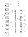
- FIG. 1 shows, in the manner of a circuit diagram, a segment 1 of a lighting device arranged in several segments.
- the lighting device has a three-wire conductor strip 2, which is conductively connected to series-connected LED elements 3, wherein each LED element 3 of a also the conductor strip 2 in the amount of each LED element surrounding, preferably crystal clear plastic housing 4 received is (see also Fig. 1a).
- the segment 1 of FIG. 1 has eight, each in a plastic housing 4 arranged, LED elements 3 (it can also be more or less provided) and a conductor strip 2 with a continuous positive conductor 5, a continuous negative conductor 6 and a, in the embodiment According to Fig. 1 seven-row center conductor 7 as a resistance cable. In a test arrangement, a seven-times series switched center conductor 7 has been designed as a resistance cable with 90.3 ohms per segment 1, proved to be particularly useful.
- the or each plastic housing 4 has a two-shell design with a first shell 9 and a second shell 10.
- the first shell 9 forms the upper housing shell
- the second shell 10 forms the lower housing shell.
- the shells 9 and 10, which are fixed to each other via Klipsetti 8, have complementary semicircular shots 11 for receiving the continuous positive conductor 5, the continuous negative conductor 6 and interrupted in the region of each plastic housing 4 center conductor 7 and a circumferential receiving groove for a too Sealant having adhesive (not shown) on.
- the procedure may be as follows:
- the upper shells (first shells 9) of possibly two segments 1 are received by an elongated, not shown, apparatus table.
- the continuous positive conductor 5 and negative conductor 6 are stripped in the necessary areas and continuously clamped in the receptacles 11 of the first Trays 9 inserted.
- the center conductor 7 is stripped to length and also inserted into the associated receptacles 11.
- the LED elements 3 are inserted into the recesses 13. Alsdann then the electrical connection by applying a contact adhesive and by activating the contact adhesive z. B. in a heating furnace or by local heaters.
- the lower shells (second shells 10) are placed on the upper shells and clipped with these.
- the so far completed on the device table lighting device can now be sealed with a sliding Kleberdosierstrom, with the seal refers to the plastic housing 4 and to the sealing and permanent fixing of their shells 9 and 10 to each other.
- the second shells 10 may each be provided with an adhesive feed opening, not shown, and possibly also with a respective not shown vent opening.
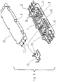
- the first shell 9 forms the housing upper shell, which is formed with the integrally formed material integrally with the lens 14 and the second shell 10, the housing lower shell.
- the shell 9 are receptacles 11 for the conductors 5-7, a recess 13 for an LED element 3, possibly a circumferential receiving groove for a not shown sealing / adhesive and free spaces for the arrangement of metallic contact elements 17 provided by corresponding recordings and the like.
- the second shell 10 are supplemented.
- the electrical contact elements 17 are z. B. made of tinned copper sheet and designed so that they come into contact with one each with an LED element 3 and the other with the positive conductor 5 (or negative conductor 6) and the center conductor 7 in contact.
- the metallic contact elements 17 have upwardly angled material tabs 18 with recesses 19 accessible from above, wherein the recessed edges act as cutting edges for cutting through the core 16 surrounding insulation of the positive conductor 5, the negative conductor 6 and the center conductor 7 are formed. It is understood that the opening width of the recesses 19 is to be matched to the respective Porterdruchmesser that a secure cutting and secure contact of the respective conductor core 16 is ensured.
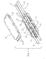
- Fig. 3 shows the clam shell plastic housing 4 without the ladder 5-7, while in Fig. 4, the plastic housing 4 with the conductors 5-7 is equipped.
- 5 shows the arrangement of the new illumination device in the receiving channel 20 of a profile strip 21, which may be an escape route marking, orientation, decoration, or the like. Profile strip 21.
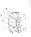
- FIG. 6 A peculiarity of the new lighting device of independent inventive significance is shown in Fig. 6 on a substantially enlarged scale training and design of the already mentioned lens 14.
- This has a flattened head surface 22, which has a radius 23 in a cone 24 passes, whose lower end coincides with the top surface of the shell 10 of the plastic housing 4.
- Outer support of the LED element 3, the lens 14 has a cylindrical recess 25 with a rounded transition to the recess bottom.
- the cone angle is based on the vertical 30 °.
- the design of the lens 14 was carried out using the law of refraction and taking into account the material constant of the material used for the production of the lens 14.
- the lines 26 indicate a beam angle of 120 °, while the lines 27 illustrate a beam angle of 180 °, because the penetrating into the lens 14 rays at point 28 undergo a corresponding change in direction.
- lens 14 is shown as an integral part of a housing shell, it is of course within the scope of the invention to provide a separately manufactured lens 14 for each LED element 3. It is also conceivable, LED elements 3 with arranged from home on it, the LEDs in the manner shown bridging lenses 14 apply.
- the invention is not limited to the illustrated embodiments, but also includes all the same in the context of the invention embodiments. Furthermore, the invention is not limited to the feature combination defined in claim 1, but may also be defined by any other combination of particular features of all individually disclosed individual features. This means that in principle each individual feature of claim 1 can be omitted or replaced by at least one individual feature disclosed elsewhere in the application documents. The present claim 1 is thus to be understood as a first formulation attempt for the identification of the invention.
Landscapes
- Engineering & Computer Science (AREA)
- General Engineering & Computer Science (AREA)
- Arrangement Of Elements, Cooling, Sealing, Or The Like Of Lighting Devices (AREA)
- Led Device Packages (AREA)
- Vehicle Body Suspensions (AREA)
- Polarising Elements (AREA)
- Seal Device For Vehicle (AREA)
- Non-Portable Lighting Devices Or Systems Thereof (AREA)
- Fastening Of Light Sources Or Lamp Holders (AREA)
Claims (13)
- Dispositif d'éclairage avec un ruban conducteur à trois brins (2) qui est relié électriquement dans la direction axiale avec des éléments de LED (3) disposés en série les uns derrière les autres, dans lequel chaque élément de LED (3) est reçu à chaque fois par un boîtier en plastique (4) au moins translucide par zones entourant aussi le ruban conducteur (2) sur la hauteur de chacun des éléments de LED (3), caractérisé en ce que chaque boîtier en plastique (4) est constitué de deux coques (9, 10) dont l'une est prévue comme une coque de réception pour la réception d'un élément de LED (3), d'une zone axiale du ruban conducteur et de moyens de contact électroconducteurs et l'autre coque comme une coque de recouvrement qui est fixée à la première coque à l'aide d'un moyen d'étanchéité, et en ce que le ruban conducteur à trois brins (2) comprend un conducteur positif continu (5), un conducteur négatif continu (6) et un conducteur neutre interrompu (7) s'étendant d'élément de LED (3) en élément de LED (3).
- Dispositif d'éclairage selon la revendication 1, caractérisé en ce qu'en guise de moyens de contact électroconducteurs entre le ruban conducteur (2) et les éléments de LED (3) sont prévus des éléments de contact métalliques (17) par lesquels le contact électrique se fait, les éléments de contact métalliques (17) qui sont reliés avec les éléments de LED (3) par simple enfichage présentant des coupures qui traversent les isolations du ruban conducteur et mettent en contact les âmes de conducteur (16) correspondantes.
- Dispositif d'éclairage selon la revendication 1, caractérisé en ce qu'en guise de moyens de contact électroconducteurs entre le ruban conducteur (2) et les éléments de LED (3) sont prévus des pâtes à souder thermoactivables, des colles de contact ou autres et des éléments de contact métalliques (17) par chacun desquels le contact électrique se fait, les éléments de contact métalliques (17) qui sont reliés avec les éléments de LED (3) par les pâtes à souder, les colles de contact ou autres présentant des coupures qui traversent les isolations du ruban conducteur et mettent en contact les âmes de conducteur (16) correspondantes.
- Dispositif d'éclairage selon la revendication 1, caractérisé en ce qu'en guise de moyens de contact électroconducteurs entre le ruban conducteur (2) qui est isolé par zones et les éléments de LED (3) sont prévues des pâtes à souder thermoactivables, des colles de contact ou autres par lesquelles le contact électrique se fait.
- Dispositif d'éclairage selon au moins l'une quelconque des revendications précédentes, caractérisé en ce que le conducteur neutre (7) est conçu comme un conducteur résistant.
- Dispositif d'éclairage selon au moins l'une quelconque des revendications précédentes, caractérisé en ce que les coques (9, 10) du boîtier en plastique (4) sont fixées l'une sur l'autre par des clips modelés.
- Dispositif d'éclairage selon au moins l'une quelconque des revendications précédentes, caractérisé en ce que les coques (9, 10) du boîtier en plastique (4) sont chacune configurées avec des réceptacles (11) complémentaires pour les différents conducteurs (5, 6, 7) du ruban conducteur (2), un élément de LED (3), les éléments de contact métalliques (17) et des moyens d'étanchéité prévus pour l'étanchéité et la liaison durable des coques (9, 10).
- Dispositif d'éclairage selon la revendication 3, caractérisé en ce que les coques (9, 10) du boîtier en plastique (4) sont configurées avec des réceptacles pour la pâte à souder et/ou la colle de contact.
- Dispositif d'éclairage selon au moins l'une quelconque des revendications précédentes, caractérisé en ce que les coques (9, 10) du boîtier en plastique (4) sont configurées comme des éléments moulés par injection transparents en PC (polycarbonate).
- Dispositif d'éclairage selon au moins l'une quelconque des revendications précédentes, caractérisé en ce qu'une coque (9, 10) du boîtier en plastique (4) est configurée avec une lentille (14) recouvrant un élément de LED (3).
- Dispositif d'éclairage selon la revendication 10, caractérisé en ce que la lentille (14) présente un façonnage pour diffuser la lumière avec un angle de rayonnement supérieur à 120°.
- Dispositif d'éclairage selon la revendication 10 ou 11, caractérisé en ce que la lentille (14) présente un façonnage pour diffuser la lumière avec un angle de rayonnement de 180°.
- Dispositif d'éclairage selon au moins l'une quelconque des revendications précédentes, caractérisé en ce que celui-ci est disposé dans un canal de réception (20) d'une baguette profilée (21) de marquage d'itinéraire de fuite, d'orientation, de décoration ou autre.
Applications Claiming Priority (2)
| Application Number | Priority Date | Filing Date | Title |
|---|---|---|---|
| DE10106961A DE10106961A1 (de) | 2001-02-15 | 2001-02-15 | Bleuchtungseinrichtung |
| DE10106961 | 2001-02-15 |
Publications (3)
| Publication Number | Publication Date |
|---|---|
| EP1233232A2 EP1233232A2 (fr) | 2002-08-21 |
| EP1233232A3 EP1233232A3 (fr) | 2005-01-19 |
| EP1233232B1 true EP1233232B1 (fr) | 2006-06-14 |
Family
ID=7674086
Family Applications (1)
| Application Number | Title | Priority Date | Filing Date |
|---|---|---|---|
| EP01128283A Expired - Lifetime EP1233232B1 (fr) | 2001-02-15 | 2001-11-29 | Dispositif d'éclairage |
Country Status (9)
| Country | Link |
|---|---|
| US (1) | US6837598B2 (fr) |
| EP (1) | EP1233232B1 (fr) |
| KR (1) | KR20020067417A (fr) |
| AT (1) | ATE330169T1 (fr) |
| DE (2) | DE10106961A1 (fr) |
| ES (1) | ES2263542T3 (fr) |
| HU (1) | HU225335B1 (fr) |
| SG (1) | SG114525A1 (fr) |
| TW (1) | TWI224181B (fr) |
Families Citing this family (59)
| Publication number | Priority date | Publication date | Assignee | Title |
|---|---|---|---|---|
| US6749310B2 (en) * | 2001-09-07 | 2004-06-15 | Contrast Lighting Services, Inc. | Wide area lighting effects system |
| US7331681B2 (en) * | 2001-09-07 | 2008-02-19 | Litepanels Llc | Lighting apparatus with adjustable lenses or filters |
| US7604361B2 (en) | 2001-09-07 | 2009-10-20 | Litepanels Llc | Versatile lighting apparatus and associated kit |
| WO2004003428A1 (fr) * | 2002-06-20 | 2004-01-08 | Eveready Battery Company, Inc. | Dispositif d'eclairage a diodes electroluminescentes |
| DE20300976U1 (de) | 2003-01-17 | 2003-04-03 | Brandau, Jonas, 10407 Berlin | Niederspannungsdekorationsleuchte mit weißen SMD-LEDs |
| DE102004004777B4 (de) | 2004-01-30 | 2013-08-29 | Osram Opto Semiconductors Gmbh | Verformbares Beleuchtungsmodul |
| US7150647B2 (en) * | 2004-02-03 | 2006-12-19 | Willis Electric Co., Ltd. | In-line socket device and its fabricating method |
| US7144139B2 (en) * | 2004-03-10 | 2006-12-05 | Kramer Eric W | Flexible surface lighting system |
| US20050201068A1 (en) * | 2004-03-10 | 2005-09-15 | Kramer Eric W. | Replaceable LED module |
| ITMI20040756A1 (it) * | 2004-04-16 | 2004-07-16 | Vlm Spa | Sistema di illuminazione modulare comprendente moduli di illuminazione a led ad alta potenza |
| US11320129B1 (en) | 2004-10-05 | 2022-05-03 | Steven Michael Colby | LED bulb including pulse generator and/or AC/DC converter |
| US8911119B1 (en) * | 2004-10-05 | 2014-12-16 | Steven M. Colby | Bulb including cover |
| US9874332B1 (en) | 2013-01-15 | 2018-01-23 | Steven Michael Colby | Bulb including removable cover |
| DE102004062469A1 (de) * | 2004-12-20 | 2006-07-06 | Kabelschlepp Gmbh | Flachkabel und Energieführungskette mit Flachkabel |
| WO2006122426A1 (fr) * | 2005-05-20 | 2006-11-23 | Tir Systems Ltd. | Module emetteur de lumiere |
| US7160140B1 (en) * | 2005-07-13 | 2007-01-09 | Gelcore Llc | LED string light engine |
| US7520771B2 (en) | 2005-07-13 | 2009-04-21 | Lumination Llc | LED string light engine and devices that are illuminated by the string light engine |
| JP4757756B2 (ja) * | 2005-11-14 | 2011-08-24 | Necライティング株式会社 | Ledランプ |
| US8465175B2 (en) | 2005-11-29 | 2013-06-18 | GE Lighting Solutions, LLC | LED lighting assemblies with thermal overmolding |
| DE102006018668B4 (de) * | 2006-04-21 | 2013-04-11 | Osram Gmbh | Modulares Beleuchtungssystem und Beleuchtungsanordnung |
| US20080137377A1 (en) * | 2006-12-11 | 2008-06-12 | Gelcore, Llc | Led light engine and method of manufacturing |
| US7600896B2 (en) * | 2007-07-27 | 2009-10-13 | Baoliang Wang | Outer case of LED module |
| US7854616B2 (en) * | 2007-10-12 | 2010-12-21 | The L.D. Kichler Co. | Positionable lighting systems and methods |
| US8599108B2 (en) * | 2007-12-11 | 2013-12-03 | Adti Media, Llc140 | Large scale LED display |
| US8648774B2 (en) | 2007-12-11 | 2014-02-11 | Advance Display Technologies, Inc. | Large scale LED display |
| CA2710110C (fr) * | 2007-12-21 | 2016-05-17 | Earl J. Hayes | Ensembles eclairage a cable souple plat et leurs procedes de fabrication |
| US20110310601A1 (en) * | 2008-02-15 | 2011-12-22 | Shu-Fa Shao | Light-emitting diode line lamp |
| JP4794587B2 (ja) * | 2008-02-19 | 2011-10-19 | シャープ株式会社 | 光源ユニット、照明装置及び表示装置 |
| US7832896B2 (en) * | 2008-04-18 | 2010-11-16 | Lumination Llc | LED light engine |
| KR200449520Y1 (ko) * | 2008-06-16 | 2010-07-15 | 주식회사 유비젼 | 플렉시블 led 램프를 갖는 가로등의 고정장치 |
| US20100014288A1 (en) * | 2008-07-15 | 2010-01-21 | Presence From Innovation, Llc | Retro-fit light stick device and secondary light source or other electrical device for use with walk-in type coolers and other product display units |
| DE102008055790B4 (de) * | 2008-11-04 | 2010-08-19 | Gernot Schneider | Schutzleiste |
| US7926978B2 (en) * | 2008-12-18 | 2011-04-19 | Kenneth Tsai | Light set with surface mounted light emitting components |
| US8397381B2 (en) * | 2009-08-06 | 2013-03-19 | Allied Bright Technology Limited | Method for manufacturing light set with surface mounted light emitting components |
| US9303861B2 (en) * | 2009-09-14 | 2016-04-05 | Us Vaopto, Inc. | Light emitting diode light source modules |
| US20110075413A1 (en) * | 2009-09-30 | 2011-03-31 | Smith Gregory S | Lighting system |
| US8342733B2 (en) * | 2009-12-14 | 2013-01-01 | Tyco Electronics Corporation | LED lighting assemblies |
| US8474998B2 (en) | 2010-03-08 | 2013-07-02 | Ge Lighting Solutions Llc | Rail and clip mounting for LED modules for fluorescent application replacement |
| DE102011003608A1 (de) * | 2010-08-20 | 2012-02-23 | Tridonic Gmbh & Co. Kg | Gehäustes LED-Modul |
| DK177534B1 (en) | 2012-03-21 | 2013-09-08 | Martin Professional As | Flexible led pixel string with two shielding ground lines |
| EP2650607B1 (fr) * | 2012-04-13 | 2014-07-23 | Hella KGaA Hueck & Co | Lumière DEL modulaire |
| DE102012216383A1 (de) * | 2012-09-14 | 2014-03-20 | Phoenix Contact Gmbh & Co. Kg | Hülsendichtung |
| DE102013203666B4 (de) * | 2013-03-04 | 2015-01-08 | Osram Gmbh | Leuchtband mit bandförmigem Substrat |
| US9464780B2 (en) | 2013-03-15 | 2016-10-11 | General Led, Inc. | LED light engine for signage |
| US10217387B2 (en) | 2013-03-15 | 2019-02-26 | General Led Opco, Llc | LED light engine for signage |
| US9626884B2 (en) | 2013-03-15 | 2017-04-18 | General Led, Inc. | LED light engine for signage |
| DE102013005230A1 (de) | 2013-03-27 | 2014-10-02 | Led-Linear Gmbh | Biegbarer LED-Streifen |
| CN103353097B (zh) * | 2013-07-16 | 2016-03-16 | 太龙(福建)商业照明股份有限公司 | 一种灯具轨道的快速警示系统 |
| USD770317S1 (en) * | 2013-07-19 | 2016-11-01 | Weidmueller Interface Gmbh & Co. Kg | LED lights |
| US20150219293A1 (en) * | 2014-02-03 | 2015-08-06 | Terry Electroncs (S.Z) Co., Ltd. | Light-emitting Device Used on Carry-on Article |
| WO2016108799A1 (fr) * | 2014-12-31 | 2016-07-07 | Eae Elektrik Aydinlatma Endüstrisi Sanayi Ve Ticaret Anonim Sirketi | Composant d'éclairage monté sur câble |
| US10205073B2 (en) | 2015-05-19 | 2019-02-12 | Seasonal Specialties, Llc | Parallel wire light string and method of manufacturer |
| CN105240811A (zh) * | 2015-10-30 | 2016-01-13 | 漳州立达信光电子科技有限公司 | Led灯电连接结构 |
| US10125964B2 (en) * | 2015-11-11 | 2018-11-13 | Itc Incorporated | Linear light connector |
| US9647349B1 (en) * | 2016-06-02 | 2017-05-09 | Elemental LED, Inc. | Through-insulation strip light connector |
| JP6507138B2 (ja) * | 2016-10-27 | 2019-04-24 | 矢崎総業株式会社 | 分岐構造及びワイヤハーネス |
| TWI641780B (zh) * | 2017-09-29 | 2018-11-21 | 美商科斯莫燈飾公司 | 燈條製造方法及用於製造燈條的繞線架 |
| CN112838153A (zh) * | 2021-02-02 | 2021-05-25 | 东莞市华彩威科技有限公司 | 一种led灯串、制造方法以及用于该led灯串中的led器件 |
| US12352407B2 (en) * | 2022-01-11 | 2025-07-08 | Signify Holding B.V. | Track lighting system having led module with light guide enclosing power track |
Family Cites Families (21)
| Publication number | Priority date | Publication date | Assignee | Title |
|---|---|---|---|---|
| US4466050A (en) * | 1981-02-27 | 1984-08-14 | Amp Incorporated | Light display assembly |
| US4924362A (en) * | 1986-08-15 | 1990-05-08 | Alliko Unlimited Corporation | Illuminated article and waterproof illuminated harness |
| SE457824B (sv) * | 1987-06-26 | 1989-01-30 | Hans Claesson | Anordning vid oeppna profilstycken |
| GB8807758D0 (en) * | 1988-03-31 | 1988-05-05 | Consumerville Ltd | Decorative lighting system |
| DE8909067U1 (de) * | 1989-07-26 | 1989-11-30 | Autronic Gmbh, 7500 Karlsruhe | Lichtleiste für einen Regaleinsatz |
| US5113329A (en) * | 1990-06-07 | 1992-05-12 | Lin Tak Huei | Tube light |
| JP2779726B2 (ja) * | 1992-02-07 | 1998-07-23 | 雅章 鶴薗 | 装飾電球の点灯装置 |
| US5321593A (en) * | 1992-10-27 | 1994-06-14 | Moates Martin G | Strip lighting system using light emitting diodes |
| US5343375A (en) * | 1993-01-28 | 1994-08-30 | H. Koch & Sons Company | Emergency egress illuminator and marker light strip |
| US5410459A (en) * | 1994-02-15 | 1995-04-25 | Yang; Ping-Kun | Lighting ornament |
| DE4412772A1 (de) * | 1994-04-14 | 1995-10-19 | Airsigna Gmbh & Co Kg | Beleuchtungseinrichtung insbesondere Notbeleuchtungseinrichtung für das Innere von Wasserfahrzeugen |
| US5672000A (en) * | 1994-09-14 | 1997-09-30 | Lin; Tayeh | Decorative lamp strip |
| DE19627856A1 (de) * | 1996-07-11 | 1998-01-15 | Happich Fahrzeug & Ind Teile | Beleuchtungsleiste und Verfahren zur Herstellung |
| US5944463A (en) * | 1997-07-22 | 1999-08-31 | Savage, Jr.; John M. | Clamp connection of electrical wiring and electrical lead structure |
| US6113248A (en) * | 1997-10-20 | 2000-09-05 | The Standard Products Company | Automated system for manufacturing an LED light strip having an integrally formed connector |
| US6017241A (en) * | 1998-01-26 | 2000-01-25 | Tivoli Industries, Inc. | Aisle lighting lampholder |
| CN2317398Y (zh) * | 1998-04-10 | 1999-05-05 | 东宝龙实业有限公司 | 布置灯饰用的塑料管状结构 |
| DE19904915A1 (de) * | 1999-02-06 | 2001-02-01 | Alcatel Sa | Feuchtigkeitsdichtes Lichtband |
| CA2402037C (fr) * | 1999-07-21 | 2010-03-09 | Teledyne Lighting And Display Products, Inc. | Appareil d'eclairage |
| DE10014804A1 (de) * | 2000-03-24 | 2001-09-27 | Swoboda Gmbh Geb | Leuchtenmodul |
| US6328593B1 (en) * | 2000-10-11 | 2001-12-11 | Chu-Chen Chang | Set of fancy lamp bulb and socket adaptor |
-
2001
- 2001-02-15 DE DE10106961A patent/DE10106961A1/de not_active Withdrawn
- 2001-11-29 EP EP01128283A patent/EP1233232B1/fr not_active Expired - Lifetime
- 2001-11-29 DE DE50110148T patent/DE50110148D1/de not_active Expired - Fee Related
- 2001-11-29 ES ES01128283T patent/ES2263542T3/es not_active Expired - Lifetime
- 2001-11-29 AT AT01128283T patent/ATE330169T1/de not_active IP Right Cessation
- 2001-12-05 TW TW090130087A patent/TWI224181B/zh not_active IP Right Cessation
-
2002
- 2002-01-04 HU HU0200032A patent/HU225335B1/hu not_active IP Right Cessation
- 2002-01-11 KR KR1020020001746A patent/KR20020067417A/ko not_active Abandoned
- 2002-01-30 SG SG200200580A patent/SG114525A1/en unknown
- 2002-02-06 US US10/068,068 patent/US6837598B2/en not_active Expired - Fee Related
Also Published As
| Publication number | Publication date |
|---|---|
| HU225335B1 (en) | 2006-09-28 |
| ATE330169T1 (de) | 2006-07-15 |
| HUP0200032A2 (en) | 2002-08-28 |
| US20020110000A1 (en) | 2002-08-15 |
| KR20020067417A (ko) | 2002-08-22 |
| TWI224181B (en) | 2004-11-21 |
| EP1233232A2 (fr) | 2002-08-21 |
| HU0200032D0 (en) | 2002-03-28 |
| SG114525A1 (en) | 2005-09-28 |
| HUP0200032A3 (en) | 2003-08-28 |
| EP1233232A3 (fr) | 2005-01-19 |
| US6837598B2 (en) | 2005-01-04 |
| DE50110148D1 (de) | 2006-07-27 |
| DE10106961A1 (de) | 2002-08-29 |
| ES2263542T3 (es) | 2006-12-16 |
Similar Documents
| Publication | Publication Date | Title |
|---|---|---|
| EP1233232B1 (fr) | Dispositif d'éclairage | |
| EP0818652B1 (fr) | Rampe d'éclairage et méthode de fabrication | |
| DE2329908C2 (fr) | ||
| DE69416602T2 (de) | Leiterverbindung und werkzeug sowie verfahren zur herstellung der verbindung | |
| DE3138047C2 (de) | Elektrisches Handbearbeitungsgerät | |
| EP1006551B1 (fr) | Lampe électrique | |
| DE19516338C1 (de) | Verbindungsklemme für elektrische Leiter | |
| DE202021103621U1 (de) | LED-Lichterkette und LED-Bauteile dieser LED-Lichterkette | |
| DE2900124C2 (de) | Elektrische Leuchte | |
| EP1022808B1 (fr) | Borne de raccordement | |
| DE1615666C3 (de) | Elektrische Klemmhülse | |
| DE3032083A1 (de) | Schmelzsicherung, insbesondere fuer gedruckte schaltungen | |
| DE202015106042U1 (de) | Leiterplatte | |
| DE2752847C3 (de) | Gehäuse mit einem darin angeordneten elektrischen Bauelement | |
| DE102011016556B4 (de) | Elektrische Kontakteinrichtung | |
| EP3477791A1 (fr) | Connecteur de dérivation | |
| EP4420199A1 (fr) | Procédé pour fixer un porte-étiquette sur une gaine isolante d'un fil électroconducteur | |
| DE102014217933A1 (de) | Elektromotor mit SMD-Bauteilen und zugehöriges Verbindungsteil | |
| EP3421955B1 (fr) | Procédé de fabrication d'un capteur électrique, pièce moulée et capteur électrique comprenant une pièce moulée | |
| DE102015110059A1 (de) | Steckverbinder und Tragschienenprofil | |
| DE2133656C3 (de) | Mehrzellenbatterie mit einem aus zwei abnehmbaren Formhälften bestehenden elektrisch nichtleitenden Gehäuse | |
| DE3237788C2 (fr) | ||
| DE102014209282A1 (de) | Elektrische Schaltungsanordnung mit Positionierungshilfe für Kabellitzen | |
| DE10218214A1 (de) | Schraubklemme zum Klemmen von isolierten und abisolierten elektrischen Leitern | |
| DE2533105C3 (de) | Vorrichtung zur Halterung und elektrischen Verbindung einer Karte mit einer hybriden, gedruckten Schaltung |
Legal Events
| Date | Code | Title | Description |
|---|---|---|---|
| PUAI | Public reference made under article 153(3) epc to a published international application that has entered the european phase |
Free format text: ORIGINAL CODE: 0009012 |
|
| AK | Designated contracting states |
Kind code of ref document: A2 Designated state(s): AT BE CH CY DE DK ES FI FR GB GR IE IT LI LU MC NL PT SE TR |
|
| AX | Request for extension of the european patent |
Free format text: AL;LT;LV;MK;RO;SI |
|
| PUAL | Search report despatched |
Free format text: ORIGINAL CODE: 0009013 |
|
| AK | Designated contracting states |
Kind code of ref document: A3 Designated state(s): AT BE CH CY DE DK ES FI FR GB GR IE IT LI LU MC NL PT SE TR |
|
| AX | Request for extension of the european patent |
Extension state: AL LT LV MK RO SI |
|
| 17P | Request for examination filed |
Effective date: 20050119 |
|
| 17Q | First examination report despatched |
Effective date: 20050705 |
|
| AKX | Designation fees paid |
Designated state(s): AT BE CH CY DE DK ES FI FR GB GR IE IT LI LU MC NL PT SE TR |
|
| GRAP | Despatch of communication of intention to grant a patent |
Free format text: ORIGINAL CODE: EPIDOSNIGR1 |
|
| GRAS | Grant fee paid |
Free format text: ORIGINAL CODE: EPIDOSNIGR3 |
|
| GRAA | (expected) grant |
Free format text: ORIGINAL CODE: 0009210 |
|
| AK | Designated contracting states |
Kind code of ref document: B1 Designated state(s): AT BE CH CY DE DK ES FI FR GB GR IE IT LI LU MC NL PT SE TR |
|
| PG25 | Lapsed in a contracting state [announced via postgrant information from national office to epo] |
Ref country code: IT Free format text: LAPSE BECAUSE OF FAILURE TO SUBMIT A TRANSLATION OF THE DESCRIPTION OR TO PAY THE FEE WITHIN THE PRESCRIBED TIME-LIMIT;WARNING: LAPSES OF ITALIAN PATENTS WITH EFFECTIVE DATE BEFORE 2007 MAY HAVE OCCURRED AT ANY TIME BEFORE 2007. THE CORRECT EFFECTIVE DATE MAY BE DIFFERENT FROM THE ONE RECORDED. Effective date: 20060614 Ref country code: IE Free format text: LAPSE BECAUSE OF FAILURE TO SUBMIT A TRANSLATION OF THE DESCRIPTION OR TO PAY THE FEE WITHIN THE PRESCRIBED TIME-LIMIT Effective date: 20060614 Ref country code: NL Free format text: LAPSE BECAUSE OF FAILURE TO SUBMIT A TRANSLATION OF THE DESCRIPTION OR TO PAY THE FEE WITHIN THE PRESCRIBED TIME-LIMIT Effective date: 20060614 |
|
| REG | Reference to a national code |
Ref country code: GB Ref legal event code: FG4D Free format text: NOT ENGLISH |
|
| REG | Reference to a national code |
Ref country code: CH Ref legal event code: EP |
|
| REG | Reference to a national code |
Ref country code: IE Ref legal event code: FG4D Free format text: LANGUAGE OF EP DOCUMENT: GERMAN |
|
| REF | Corresponds to: |
Ref document number: 50110148 Country of ref document: DE Date of ref document: 20060727 Kind code of ref document: P |
|
| PG25 | Lapsed in a contracting state [announced via postgrant information from national office to epo] |
Ref country code: DK Free format text: LAPSE BECAUSE OF FAILURE TO SUBMIT A TRANSLATION OF THE DESCRIPTION OR TO PAY THE FEE WITHIN THE PRESCRIBED TIME-LIMIT Effective date: 20060914 |
|
| REG | Reference to a national code |
Ref country code: SE Ref legal event code: TRGR |
|
| GBT | Gb: translation of ep patent filed (gb section 77(6)(a)/1977) |
Effective date: 20060923 |
|
| REG | Reference to a national code |
Ref country code: GR Ref legal event code: EP Ref document number: 20060403207 Country of ref document: GR |
|
| PG25 | Lapsed in a contracting state [announced via postgrant information from national office to epo] |
Ref country code: PT Free format text: LAPSE BECAUSE OF FAILURE TO SUBMIT A TRANSLATION OF THE DESCRIPTION OR TO PAY THE FEE WITHIN THE PRESCRIBED TIME-LIMIT Effective date: 20061114 |
|
| PG25 | Lapsed in a contracting state [announced via postgrant information from national office to epo] |
Ref country code: MC Free format text: LAPSE BECAUSE OF NON-PAYMENT OF DUE FEES Effective date: 20061130 Ref country code: LI Free format text: LAPSE BECAUSE OF NON-PAYMENT OF DUE FEES Effective date: 20061130 Ref country code: BE Free format text: LAPSE BECAUSE OF NON-PAYMENT OF DUE FEES Effective date: 20061130 Ref country code: CH Free format text: LAPSE BECAUSE OF NON-PAYMENT OF DUE FEES Effective date: 20061130 |
|
| NLV1 | Nl: lapsed or annulled due to failure to fulfill the requirements of art. 29p and 29m of the patents act | ||
| REG | Reference to a national code |
Ref country code: ES Ref legal event code: FG2A Ref document number: 2263542 Country of ref document: ES Kind code of ref document: T3 |
|
| ET | Fr: translation filed | ||
| REG | Reference to a national code |
Ref country code: IE Ref legal event code: FD4D |
|
| PLBE | No opposition filed within time limit |
Free format text: ORIGINAL CODE: 0009261 |
|
| STAA | Information on the status of an ep patent application or granted ep patent |
Free format text: STATUS: NO OPPOSITION FILED WITHIN TIME LIMIT |
|
| 26N | No opposition filed |
Effective date: 20070315 |
|
| REG | Reference to a national code |
Ref country code: CH Ref legal event code: PL |
|
| BERE | Be: lapsed |
Owner name: HAPPICH FAHRZEUG- UND INDUSTRIETEILE G.M.B.H. Effective date: 20061130 |
|
| PG25 | Lapsed in a contracting state [announced via postgrant information from national office to epo] |
Ref country code: AT Free format text: LAPSE BECAUSE OF NON-PAYMENT OF DUE FEES Effective date: 20061129 |
|
| PG25 | Lapsed in a contracting state [announced via postgrant information from national office to epo] |
Ref country code: TR Free format text: LAPSE BECAUSE OF FAILURE TO SUBMIT A TRANSLATION OF THE DESCRIPTION OR TO PAY THE FEE WITHIN THE PRESCRIBED TIME-LIMIT Effective date: 20060614 Ref country code: LU Free format text: LAPSE BECAUSE OF NON-PAYMENT OF DUE FEES Effective date: 20061129 |
|
| PG25 | Lapsed in a contracting state [announced via postgrant information from national office to epo] |
Ref country code: CY Free format text: LAPSE BECAUSE OF FAILURE TO SUBMIT A TRANSLATION OF THE DESCRIPTION OR TO PAY THE FEE WITHIN THE PRESCRIBED TIME-LIMIT Effective date: 20060614 |
|
| PGFP | Annual fee paid to national office [announced via postgrant information from national office to epo] |
Ref country code: DE Payment date: 20081105 Year of fee payment: 8 |
|
| PGFP | Annual fee paid to national office [announced via postgrant information from national office to epo] |
Ref country code: ES Payment date: 20081111 Year of fee payment: 8 Ref country code: FI Payment date: 20081016 Year of fee payment: 8 |
|
| PGFP | Annual fee paid to national office [announced via postgrant information from national office to epo] |
Ref country code: IT Payment date: 20081020 Year of fee payment: 8 Ref country code: SE Payment date: 20081020 Year of fee payment: 8 |
|
| PGFP | Annual fee paid to national office [announced via postgrant information from national office to epo] |
Ref country code: FR Payment date: 20081013 Year of fee payment: 8 |
|
| PGFP | Annual fee paid to national office [announced via postgrant information from national office to epo] |
Ref country code: GB Payment date: 20081022 Year of fee payment: 8 Ref country code: GR Payment date: 20081017 Year of fee payment: 8 |
|
| EUG | Se: european patent has lapsed | ||
| GBPC | Gb: european patent ceased through non-payment of renewal fee |
Effective date: 20091129 |
|
| REG | Reference to a national code |
Ref country code: FR Ref legal event code: ST Effective date: 20100730 |
|
| PG25 | Lapsed in a contracting state [announced via postgrant information from national office to epo] |
Ref country code: FI Free format text: LAPSE BECAUSE OF NON-PAYMENT OF DUE FEES Effective date: 20091129 |
|
| PG25 | Lapsed in a contracting state [announced via postgrant information from national office to epo] |
Ref country code: FR Free format text: LAPSE BECAUSE OF NON-PAYMENT OF DUE FEES Effective date: 20091130 Ref country code: GR Free format text: LAPSE BECAUSE OF NON-PAYMENT OF DUE FEES Effective date: 20100602 |
|
| PG25 | Lapsed in a contracting state [announced via postgrant information from national office to epo] |
Ref country code: DE Free format text: LAPSE BECAUSE OF NON-PAYMENT OF DUE FEES Effective date: 20100601 |
|
| PG25 | Lapsed in a contracting state [announced via postgrant information from national office to epo] |
Ref country code: GB Free format text: LAPSE BECAUSE OF NON-PAYMENT OF DUE FEES Effective date: 20091129 |
|
| REG | Reference to a national code |
Ref country code: ES Ref legal event code: FD2A Effective date: 20110309 |
|
| PG25 | Lapsed in a contracting state [announced via postgrant information from national office to epo] |
Ref country code: IT Free format text: LAPSE BECAUSE OF NON-PAYMENT OF DUE FEES Effective date: 20091129 |
|
| PG25 | Lapsed in a contracting state [announced via postgrant information from national office to epo] |
Ref country code: SE Free format text: LAPSE BECAUSE OF NON-PAYMENT OF DUE FEES Effective date: 20091130 |
|
| PG25 | Lapsed in a contracting state [announced via postgrant information from national office to epo] |
Ref country code: ES Free format text: LAPSE BECAUSE OF NON-PAYMENT OF DUE FEES Effective date: 20110308 |
|
| PG25 | Lapsed in a contracting state [announced via postgrant information from national office to epo] |
Ref country code: ES Free format text: LAPSE BECAUSE OF NON-PAYMENT OF DUE FEES Effective date: 20091130 |