EP1233235A2 - Verfahren und Vorrichtung zum Reduzieren der sauren Schadstoffemissionen von Industrieanlagen - Google Patents
Verfahren und Vorrichtung zum Reduzieren der sauren Schadstoffemissionen von Industrieanlagen Download PDFInfo
- Publication number
- EP1233235A2 EP1233235A2 EP02003515A EP02003515A EP1233235A2 EP 1233235 A2 EP1233235 A2 EP 1233235A2 EP 02003515 A EP02003515 A EP 02003515A EP 02003515 A EP02003515 A EP 02003515A EP 1233235 A2 EP1233235 A2 EP 1233235A2
- Authority
- EP
- European Patent Office
- Prior art keywords
- magnesium
- fuel
- burner
- solution
- combustion
- Prior art date
- Legal status (The legal status is an assumption and is not a legal conclusion. Google has not performed a legal analysis and makes no representation as to the accuracy of the status listed.)
- Withdrawn
Links
Images


Classifications
-
- F—MECHANICAL ENGINEERING; LIGHTING; HEATING; WEAPONS; BLASTING
- F23—COMBUSTION APPARATUS; COMBUSTION PROCESSES
- F23K—FEEDING FUEL TO COMBUSTION APPARATUS
- F23K5/00—Feeding or distributing other fuel to combustion apparatus
- F23K5/02—Liquid fuel
- F23K5/08—Preparation of fuel
- F23K5/10—Mixing with other fluids
-
- C—CHEMISTRY; METALLURGY
- C10—PETROLEUM, GAS OR COKE INDUSTRIES; TECHNICAL GASES CONTAINING CARBON MONOXIDE; FUELS; LUBRICANTS; PEAT
- C10L—FUELS NOT OTHERWISE PROVIDED FOR; NATURAL GAS; SYNTHETIC NATURAL GAS OBTAINED BY PROCESSES NOT COVERED BY SUBCLASSES C10G OR C10K; LIQUIFIED PETROLEUM GAS; USE OF ADDITIVES TO FUELS OR FIRES; FIRE-LIGHTERS
- C10L1/00—Liquid carbonaceous fuels
- C10L1/32—Liquid carbonaceous fuels consisting of coal-oil suspensions or aqueous emulsions or oil emulsions
- C10L1/328—Oil emulsions containing water or any other hydrophilic phase
-
- F—MECHANICAL ENGINEERING; LIGHTING; HEATING; WEAPONS; BLASTING
- F23—COMBUSTION APPARATUS; COMBUSTION PROCESSES
- F23K—FEEDING FUEL TO COMBUSTION APPARATUS
- F23K5/00—Feeding or distributing other fuel to combustion apparatus
- F23K5/02—Liquid fuel
- F23K5/08—Preparation of fuel
- F23K5/10—Mixing with other fluids
- F23K5/12—Preparing emulsions
-
- F—MECHANICAL ENGINEERING; LIGHTING; HEATING; WEAPONS; BLASTING
- F23—COMBUSTION APPARATUS; COMBUSTION PROCESSES
- F23K—FEEDING FUEL TO COMBUSTION APPARATUS
- F23K2300/00—Pretreatment and supply of liquid fuel
- F23K2300/20—Supply line arrangements
Definitions
- the invention relates to a method for reducing the acidic pollutant emissions, especially the Sulfur trioxide emission, from industrial plants with at least one burner for burning liquid fossil fuels.
- the Invention of flue gas neutralization in the Heavy oil combustion is particularly advantageous.
- Flue gas neutralization in the combustion of fossil fuels has been carried out for a long time in order to reduce the SO 3 content in the flue gas.
- Minimizing the SO 3 content significantly reduces the tendency to contamination and corrosion in the high and low temperature range of the boiler.
- soot flake emissions are avoided and the free and clean surfaces of the boiler enable more effective heat transfer.
- EP 0 426 978 A1 discloses a process in which a reducing agent containing urea and releasing ammonia is added to the flue gases to reduce the nitrogen oxide content. From DE 44 17 874 C2 it is known to inject an aqueous solution of a magnesium compound together with a NO x reducing agent into the combustion chamber. This is intended to prevent the formation of ammonium bisulfates.
- the invention is based on the object of a method and a device of the type described above train that on the one hand the handling of the additives can be facilitated. To the others are said to have an improved response with regard to the Utilization of the introduced active ingredient can be achieved.
- the object is achieved according to the invention in that before combustion with an emulsion of the fuel a solution of a magnesium-containing active substance or a magnesium compound and the burner is fed.
- This emulsion with the fuel can for example with an aqueous solution water-soluble magnesium-containing active ingredient or one Magnesium compound are formed.
- the active ingredient namely the magnesium compound, in of its own liquid phase finely divided.
- the Emulsion is finely atomized in the fuel nozzle the consequence that almost the entire brought magnesium-containing compound are reacted can. There is no reaction with the fuel ash.
- this solution of a magnesium-containing Active ingredient or a magnesium compound Combustion gases are supplied in the form of an aerosol.
- the solution can also be an aqueous solution be water-soluble magnesium compound.
- the aerosol is preferably generated with compressed air, which the Solution to be introduced is fed before atomization.
- the magnesium-containing active ingredient or the magnesium compound is in its own liquid phase.
- a fine distribution of the liquid phase is effected, so that almost all of the magnesium-containing compound introduced can react, for example, to MgSO 4 .
- the aerosol is used in several Place along the circumference of the combustion tube, the Flue gas pipe or the train to form a at least approximate over the cross section complete shield of the aerosol the combustion gases is fed.
- This has the advantage that the entire Flue gas cross section is reached by the active ingredient.
- the Non-neutralized flue gases can therefore slip prevented or at least significantly reduced.
- the magnesium-containing active ingredient or Magnesium compound can be an organic or a salt be or contain an inorganic acid. Also can be provided that the magnesium-containing Active ingredient or the magnesium compound magnesium nitrate or / and contains magnesium acetate.
- the added solution also contain emulsifiers. The fine distribution when atomizing the emulsion in the The burning nozzle and a clean flame pattern remain receive.
- the Dosing devices each include a control valve.
- Control valves can be regulated and controlled in a simple manner be checked so that each burner accordingly the amount required for its individual consumption can be supplied to the solution.
- Fig. 1 is a system for fuel supply of an additive to reduce the acid Pollutant emissions from industrial plants shown. It is a first reservoir 1 with a concentrate of magnesium-containing active ingredient or the magnesium compound available. This magnesium-containing active ingredient can for example a 20 to 60% magnesium acetate or Magnesium nitrate solution. A dilution with water from 1: 2 to 1:50 and in particular from 1: 5 to 1:15 considered appropriate. It is a second Reservoir 2 provided in which the carrier water for Formation of an aqueous solution in the desired Final concentration of the solution to be supplied is included.
- this second reservoir 2 can a central water supply will be replaced.
- the desired amount of concentrate from the Storage container 1 and the desired amount of Carrier water from the reservoir 2 are over Measuring devices 3 and pumps 4 a default container 5 fed.
- this default container 5 is accordingly Solution available in the desired concentration is fed to the burners.
- the default container 5 stands in conjunction with a main distribution 6, which in turn is connected to a plurality of sub-distributions 7.
- Each sub-distribution 7 is with one or more Feeders 8 connected to the Fuel line 9 of a burner, not shown lead.
- the arrangement is such that the feed device 8 in the flow direction of the Fuel in front of the fuel nozzle and behind the Fuel return flows into the fuel line 9.
- the feed device 8 further comprises a control valve 10, through which the desired amount of the aqueous solution Fuel is supplied to form an emulsion.
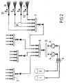
- the additive supply on the flue gas side is one Industrial plant with a variety of supplies Incinerators shown. From the principle This additive feed corresponds to the structure fuel-side additive feed, and they are the same or equivalent components with the same reference numerals Mistake.
- a Subdistribution 7 has a plurality of nozzles 11 connected through which the additive in the Combustion gases arrives.
- the nozzles can Combustion pipe and / or in the flue gas duct and / or in Boiler train of the incinerator be present. It can be provided, for example, that everyone Sub-distribution 7 the number of nozzles 11 is assigned, which are arranged in a combustion tube. It is but also possible that a sub-distribution 7 nozzles in several combustion pipes supplied with the additive.
- the additive is used in the combustion gases Combustion tube supplied in the form of an aerosol.
- the compressed air can the additive with a pressure of 3.0 to 10.0 and in particular 5.0 to 7.0 bar can be supplied. Thereby is achieved that the aerosol far into the Combustion pipe can be injected into it.
- Fig. 3 is a possible arrangement of the nozzles Delivery of the aerosol shown in the combustion tube.
- the Nozzles 11 are substantially uniform along that Distributed circumference and in the middle of the combustion tube directed. Basically, every other orientation is also the nozzles are useful, as long as one is essentially complete shielding of the cross section with the aerosol is achieved. Overall, it can be effective Neutralize the combustion gases.
- Fig. 1 shows the fuel supply of a Additive.
- 2 and 3 show the flue gas side Addition of an additive.
- Both additives have the same active ingredient, namely a magnesium-containing one Compound, which preferably as an aqueous solution Fuel or the combustion gases is fed.
- a magnesium-containing one Compound which preferably as an aqueous solution Fuel or the combustion gases is fed.
- an addition of, for example, 5-500 mg of MgO per 1 kg Fuel The amount fed in both Process will vary according to specific properties of the fuel and the sulfur trioxide content in the exhaust gas sized.
- both methods can be used in combination. This can be done, for example be provided that a 6 behind the main distribution Sub-distribution 7 for supplying aerosol nozzles 11 is provided, while another sub-distribution 7 the Feeding devices for the fuel side Dosages 10 supplied. Even if the respective Feeders or nozzles with one different pressure can work through a corresponding number and arrangement of Throttle valves or additional pumps be generated.
Landscapes
- Engineering & Computer Science (AREA)
- Chemical & Material Sciences (AREA)
- Combustion & Propulsion (AREA)
- Mechanical Engineering (AREA)
- General Engineering & Computer Science (AREA)
- Oil, Petroleum & Natural Gas (AREA)
- Chemical Kinetics & Catalysis (AREA)
- General Chemical & Material Sciences (AREA)
- Organic Chemistry (AREA)
- Treating Waste Gases (AREA)
Abstract
Description
- Fig. 1
- das Schema einer zentralen Additivzuführung bei einer Industrieanlage mit mehreren Brennern.
- Fig. 2
- das Schema einer Additivzuführung bei einer Industrieanlage mit mehreren Verbrennungsrohren, in die das Additiv zugeführt wird, und
- Fig. 3
- einen Querschnitt eines Verbrennungsrohrs mit einer Vielzahl von Düsen zur Einbringung des Aerosols.
Claims (12)
- Verfahren zum Reduzieren der sauren Schadstoffemissionen, insbesondere der Schwefeltrioxid-Emission, von Industrieanlagen mit wenigstens einem Brenner zum Verbrennen von flüssigen fossilen Brennstoffen, dadurch gekennzeichnet, daß vor der Verbrennung eine Emulsion des Brennstoffs mit einer Lösung eines magnesiumhaltigen Wirkstoffs oder einer Magnesiumverbindung gebildet und dem Brenner zugeführt wird.
- Verfahren zum Reduzieren der sauren Schadstoffemissionen, insbesondere der Schwefeltrioxid-Emission, von Industrieanlagen mit wenigstens einem Brenner zum Verbrennen von flüssigen fossilen Brennstoffen, dadurch gekennzeichnet, daß dem Brennstoff vor der Verbrennung eine wässrige Lösung eines wasserlöslichen magnesiumhaltigen Wirkstoffs oder einer Magnesiumverbindung zugeführt wird.
- Verfahren nach Anspruch 1, dadurch gekennzeichnet, daß die Lösung dem Brennstoff mit Überdruck zugeführt wird.
- Verfahren zum Reduzieren der sauren Schadstoffemissionen, insbesondere der Schwefeltrioxid-Emission, von Industrieanlagen mit wenigstens einem Brenner zum Verbrennen von flüssigen fossilen Brennstoffen, dadurch gekennzeichnet, daß den Verbrennungsgasen ein Aerosol einer wässrigen Lösung einer wasserlöslichen Magnesiumverbindung zugeführt wird.
- Verfahren nach Anspruch 4, dadurch gekennzeichnet, daß das Aerosol an mehreren Stellen entlang dem Umfang des Verbrennungsrohrs unter Bildung eines über den Querschnitt zumindest näherungsweisen vollständigen Schirms des Aerosols den Verbrennungsgasen zugeführt wird.
- Verfahren nach einem der Ansprüche 1 bis 5, dadurch gekennzeichnet, daß der magnesiumhaltige Wirkstoff beziehungsweise die Magnesiumverbindung ein Salz einer organischen oder einer anorganischen Säure ist oder diese enthält.
- Verfahren nach einem der Ansprüche 1 bis 6, dadurch gekennzeichnet, daß der magnesiumhaltige Wirkstoff oder die Magnesiumverbindung Magnesiumnitrat und/oder Magnesiumacetat enthält.
- Vorrichtung zum Reduzieren der sauren Schadstoffemissionen, insbesondere der Schwefeltrioxid-Emission, von Industrieanlagen, mit einem oder einer Vielzahl von Brennern zum Verbrennen von flüssigen fossilen Brennstoffen, dadurch gekennzeichnet, daß wenigstens einem und vorzugsweise jedem Brenner eine Dosiereinrichtung (10) und eine Zuführeinrichtung (8) zugeordnet ist, die in die Brennstoffleitung (9) mündet und aus einem zentralen Vorgabebehälter (5) dem flüssigen Brennstoff eine Lösung einer Magnesiumverbindung unter Bildung einer Emulsion mit dem Brennstoff zuführt.
- Vorrichtung nach Anspruch 8, dadurch gekennzeichnet, daß die Zuführeinrichtung in Strömungsrichtung des Brennstoffs hinter der Brennstoffrückführung eines jeden Brenners in die Brennstoffleitung mündet.
- Vorrichtung nach einem der Ansprüche 8 oder 9, dadurch gekennzeichnet, daß die Zuführeinrichtung in Strömungsrichtung des Brennstoffs kurz vor der Brennerdüse in die Brennstoffleitung mündet.
- Vorrichtung nach einem der Ansprüche 8 bis 10, dadurch gekennzeichnet, daß die Lösung unter Druck den einzelnen Brennern zugeführt wird, und daß die Dosiereinrichtungen jeweils ein Stellventil (10) umfassen.
- Vorrichtung zum Reduzieren der sauren Schadstoffemissionen, insbesondere der Schwefeltrioxid-Emission, von Industrieanlagen, mit einem oder einer Vielzahl von Brennern zum Verbrennen von flüssigen fossilen Brennstoffen, dadurch gekennzeichnet, daß in wenigstens einem und vorzugsweise in jedem Verbrennungsrohr und/oder Rauchgaskanal und/oder Kesselzug wenigstens eine Düse (11) mit Druckluftzuführung (12) angeordnet ist, welche Düsen aus einem zentralen Vorgabebehälter (5) mit einer Lösung einer Magnesiumverbindung versorgt werden und diese mit der Druckluft unter Bildung eines Aerosols in die Verbrennungsgase eindüsen.
Applications Claiming Priority (4)
| Application Number | Priority Date | Filing Date | Title |
|---|---|---|---|
| GR20010100092A GR1003899B (el) | 2001-02-19 | 2001-02-19 | Μεθοδος ελεγχου και περιορισμου τοξικων οξινων εκπομπων βιομηχανικων εγκαταστασεων, μεσω ψεκασμου υδατοδιαλυτου οργανομεταλλικου προσθετου του μαγνησιου πολλαπλα ρυθμιζομενου, ανα στοιχειο ψεκασμου στην κορυφη και στο περας της εστιας καυσης. |
| GR2001100091 | 2001-02-19 | ||
| GR2001100092 | 2001-02-19 | ||
| GR20010100091A GR1003835B (el) | 2001-02-19 | 2001-02-19 | Διαταξη συστηματος πολλαπλης και ρυθμιζομενης εγχυσης σε ολους τους τυπους καυστηρων και ανα καυστηρα με χρηση υδατοδιαλυτων οργανομεταλλικων προσθετων του μαγνησιου για τον ελεγχο και περιο ρισμο των τοξικων οξινων εκπομπων βιομηχανικων εγκαταστασεων |
Publications (2)
| Publication Number | Publication Date |
|---|---|
| EP1233235A2 true EP1233235A2 (de) | 2002-08-21 |
| EP1233235A3 EP1233235A3 (de) | 2002-11-13 |
Family
ID=26316695
Family Applications (1)
| Application Number | Title | Priority Date | Filing Date |
|---|---|---|---|
| EP02003515A Withdrawn EP1233235A3 (de) | 2001-02-19 | 2002-02-15 | Verfahren und Vorrichtung zum Reduzieren der sauren Schadstoffemissionen von Industrieanlagen |
Country Status (2)
| Country | Link |
|---|---|
| US (1) | US20030027089A1 (de) |
| EP (1) | EP1233235A3 (de) |
Cited By (1)
| Publication number | Priority date | Publication date | Assignee | Title |
|---|---|---|---|---|
| EP3030335A1 (de) | 2013-08-08 | 2016-06-15 | Babcock and Wilcox Power Generation Group, Inc. | System und verfahren zur verringerung von zur quecksilberkontrolle erforderlichen halogenebenen |
Families Citing this family (4)
| Publication number | Priority date | Publication date | Assignee | Title |
|---|---|---|---|---|
| FR2861605B1 (fr) * | 2003-11-05 | 2005-12-30 | Inst Francais Du Petrole | Methode de melange et de distribution d'une phase liquide et d'une phase gazeuse |
| GB0421837D0 (en) * | 2004-10-01 | 2004-11-03 | Eps Technologies Inc | Catalyst delivery system |
| US7509156B2 (en) * | 2005-05-18 | 2009-03-24 | Clarian Health Partners, Inc. | System for managing glucose levels in patients with diabetes or hyperglycemia |
| US9719681B2 (en) * | 2011-06-06 | 2017-08-01 | General Electric Company | System and method for supplying fuel |
Citations (2)
| Publication number | Priority date | Publication date | Assignee | Title |
|---|---|---|---|---|
| EP0426978A1 (de) | 1989-09-15 | 1991-05-15 | ERC Emissions-Reduzierungs-Concepte GmbH | Verfahren zur selektiven nicht-katalytischen Reduktion der Emission von Schadstoffen aus ölbefeuerten Kesselanlagen |
| DE4417874C2 (de) | 1994-05-24 | 1999-02-04 | Erc Emissions Reduzierungs Con | Verfahren zur Verminderung von Kesselbelägen im Zusammenhang mit NO¶x¶-reduzierenden Maßnahmen |
Family Cites Families (15)
| Publication number | Priority date | Publication date | Assignee | Title |
|---|---|---|---|---|
| US2982215A (en) * | 1958-09-02 | 1961-05-02 | William E Baker | Atomizing pump |
| BE681068A (de) * | 1966-05-16 | 1966-10-31 | ||
| US3948617A (en) * | 1972-10-11 | 1976-04-06 | Benjamin Withorn | Method of reducing sulphur dioxide emissions from combustible materials |
| FR2290240A1 (fr) * | 1974-11-06 | 1976-06-04 | Unibra Sa | Perfectionnements a la desulfuration des gaz |
| IL53684A0 (en) * | 1977-01-14 | 1978-03-10 | Seatrain Lines Inc | Methods and apparatus for processing petroleum fuel for gas turbine engines |
| US4214435A (en) * | 1977-07-25 | 1980-07-29 | General Electric Company | Method for reducing nitrous oxide emissions from a gas turbine engine |
| YU41704B (en) * | 1979-03-30 | 1987-12-31 | Solar 77 Spa | Device for dosig, mixing and emulsifying non-mixable liguids for liguid fuel |
| US4555996A (en) * | 1984-07-06 | 1985-12-03 | Acurex Corp. | Method for reduction of sulfur products in the exhaust gases of a combustion chamber |
| US5513584A (en) * | 1986-06-17 | 1996-05-07 | Intevep, S.A. | Process for the in-situ production of a sorbent-oxide aerosol used for removing effluents from a gaseous combustion stream |
| US4722287A (en) * | 1986-07-07 | 1988-02-02 | Combustion Engineering, Inc. | Sorbent injection system |
| DE3635897A1 (de) * | 1986-10-22 | 1988-05-05 | Krc Umwelttechnik Gmbh | Verfahren und vorrichtung zur reinigung von rauchgasen |
| US4842834A (en) * | 1987-02-02 | 1989-06-27 | Fuel Tech, Inc. | Process for reducing the concentration of pollutants in an effluent |
| US5312605A (en) * | 1991-12-11 | 1994-05-17 | Northeastern University | Method for simultaneously removing SO2 and NOX pollutants from exhaust of a combustion system |
| US5964906A (en) * | 1997-11-10 | 1999-10-12 | Intevep, S.A. | Emulsion with solid additive in hydrocarbon phase and process for preparing same |
| ATE311245T1 (de) * | 1998-05-20 | 2005-12-15 | Ernesto Marelli | Verfahren zur herstellung von emulsionen, insbesondere emulsionen von flüssigen brennstoffen und wasser, und vorrichtung dafür |
-
2002
- 2002-02-14 US US10/076,217 patent/US20030027089A1/en not_active Abandoned
- 2002-02-15 EP EP02003515A patent/EP1233235A3/de not_active Withdrawn
Patent Citations (2)
| Publication number | Priority date | Publication date | Assignee | Title |
|---|---|---|---|---|
| EP0426978A1 (de) | 1989-09-15 | 1991-05-15 | ERC Emissions-Reduzierungs-Concepte GmbH | Verfahren zur selektiven nicht-katalytischen Reduktion der Emission von Schadstoffen aus ölbefeuerten Kesselanlagen |
| DE4417874C2 (de) | 1994-05-24 | 1999-02-04 | Erc Emissions Reduzierungs Con | Verfahren zur Verminderung von Kesselbelägen im Zusammenhang mit NO¶x¶-reduzierenden Maßnahmen |
Cited By (1)
| Publication number | Priority date | Publication date | Assignee | Title |
|---|---|---|---|---|
| EP3030335A1 (de) | 2013-08-08 | 2016-06-15 | Babcock and Wilcox Power Generation Group, Inc. | System und verfahren zur verringerung von zur quecksilberkontrolle erforderlichen halogenebenen |
Also Published As
| Publication number | Publication date |
|---|---|
| US20030027089A1 (en) | 2003-02-06 |
| EP1233235A3 (de) | 2002-11-13 |
Similar Documents
| Publication | Publication Date | Title |
|---|---|---|
| DE2739509C2 (de) | Verfahren und Vorrichtung zur Reinigung eines Abgasstromes | |
| DE69318461T2 (de) | Verfahren und Vorrichtung zur Entfernung von Stickoxyden | |
| DE102008004008A1 (de) | Verfahren und Einrichtung zur Reduktion von NOx-Emissionen aus gewerblichen Verbrennungsanlagen | |
| EP0278241B1 (de) | Verfahren zum Einmischen von Ammoniak in einen Rauchgasstrom | |
| DE3441675C2 (de) | ||
| WO1999024150A1 (de) | Einrichtung zum einbringen eines flüssigen reduktionsmittels in eine abgas-reinigungsanlage | |
| EP0426978A1 (de) | Verfahren zur selektiven nicht-katalytischen Reduktion der Emission von Schadstoffen aus ölbefeuerten Kesselanlagen | |
| DE102017001025A1 (de) | Düsenlanze, Verbrennungsanlage und Verfahren zur Abgasbehandlung | |
| DE202023102327U1 (de) | Tangential gefeuertes Kohlenstaubkesselsystem unter Mischung von Ammoniakgas für Verbrennung | |
| EP0364712A1 (de) | Verfahren zum Entfernen von Stickoxyden aus Rauchgasen | |
| DE2750672A1 (de) | Waermeerzeugungsverfahren und vorrichtung zu seiner durchfuehrung | |
| EP1233235A2 (de) | Verfahren und Vorrichtung zum Reduzieren der sauren Schadstoffemissionen von Industrieanlagen | |
| DE60107351T2 (de) | Verfahren zur Zuführung von Reagenz | |
| DE3935402C1 (de) | ||
| DE69304318T2 (de) | Verfahren und vorrichtung zur selektiven reduktion des stickstoffoxidgehaltes von abgasen einer ofenanlage | |
| DE202023107072U1 (de) | System zur Unterdrückung der Bildung von Dioxinen während des Trocknungsprozesses von Kohlepulver unter Verwendung von Ofenrauch | |
| DE3751817T2 (de) | Verfahren und Vorrichtung um Schwefeldioxid auf Rauchgas zu reduzieren | |
| DE4436660A1 (de) | Vereinfachte Trockenentschwefelungsanlage | |
| EP2001599B1 (de) | Verfahren und anlage zum feinstverteilen und austragen eines reiz- oder kampfstoffes | |
| WO1989008803A1 (fr) | Procede et dispositif pour le fonctionnement d'une turbine a gaz avec injection d'additifs | |
| AT392529B (de) | Verfahren zum verteilen eines brennstoff-luft- gemisches im brennraum eines brennerbeheizten geraetes und brenner zur durchfuehrung des verfahrens | |
| DE3340892C2 (de) | ||
| DE68919320T2 (de) | Verfahren zur ermässigung der konzentration von schadstoffen in abgasen. | |
| DE102018101865A1 (de) | Verfahren zur Stickoxidreduzierung in Rauchgasen von Abfallverbrennungsanlagen | |
| DE3318374A1 (de) | Verfahren zum abtrennen von schwefeloxiden aus verbrennungsgasen sowie vorrichtung zur durchfuehrung des verfahrens |
Legal Events
| Date | Code | Title | Description |
|---|---|---|---|
| PUAI | Public reference made under article 153(3) epc to a published international application that has entered the european phase |
Free format text: ORIGINAL CODE: 0009012 |
|
| AK | Designated contracting states |
Kind code of ref document: A2 Designated state(s): AT BE CH CY DE DK ES FI FR GB GR IE IT LI LU MC NL PT SE TR |
|
| AX | Request for extension of the european patent |
Free format text: AL;LT;LV;MK;RO;SI |
|
| PUAL | Search report despatched |
Free format text: ORIGINAL CODE: 0009013 |
|
| RIC1 | Information provided on ipc code assigned before grant |
Free format text: 7F 23K 5/12 A, 7F 23K 5/10 B, 7C 10L 1/32 B, 7F 23J 7/00 B, 7F 23J 15/00 B |
|
| AK | Designated contracting states |
Kind code of ref document: A3 Designated state(s): AT BE CH CY DE DK ES FI FR GB GR IE IT LI LU MC NL PT SE TR |
|
| AX | Request for extension of the european patent |
Free format text: AL;LT;LV;MK;RO;SI |
|
| AKX | Designation fees paid | ||
| REG | Reference to a national code |
Ref country code: DE Ref legal event code: 8566 |
|
| STAA | Information on the status of an ep patent application or granted ep patent |
Free format text: STATUS: THE APPLICATION IS DEEMED TO BE WITHDRAWN |
|
| 18D | Application deemed to be withdrawn |
Effective date: 20030514 |