EP1233247B1 - Evaluation de l'alignement respectif de deux corps ( poulies ) avec un réflecteur convexe ou semi transparent - Google Patents
Evaluation de l'alignement respectif de deux corps ( poulies ) avec un réflecteur convexe ou semi transparent Download PDFInfo
- Publication number
- EP1233247B1 EP1233247B1 EP01130412A EP01130412A EP1233247B1 EP 1233247 B1 EP1233247 B1 EP 1233247B1 EP 01130412 A EP01130412 A EP 01130412A EP 01130412 A EP01130412 A EP 01130412A EP 1233247 B1 EP1233247 B1 EP 1233247B1
- Authority
- EP
- European Patent Office
- Prior art keywords
- mark
- arrangement according
- reflector
- labelled
- reference device
- Prior art date
- Legal status (The legal status is an assumption and is not a legal conclusion. Google has not performed a legal analysis and makes no representation as to the accuracy of the status listed.)
- Expired - Lifetime
Links
- 238000000034 method Methods 0.000 claims abstract description 9
- 238000006073 displacement reaction Methods 0.000 description 5
- 238000005259 measurement Methods 0.000 description 4
- 239000000853 adhesive Substances 0.000 description 2
- 230000001070 adhesive effect Effects 0.000 description 2
- 239000004065 semiconductor Substances 0.000 description 2
- 239000012780 transparent material Substances 0.000 description 2
- 229920005372 Plexiglas® Polymers 0.000 description 1
- 238000005422 blasting Methods 0.000 description 1
- 230000001419 dependent effect Effects 0.000 description 1
- 230000000694 effects Effects 0.000 description 1
- 239000005337 ground glass Substances 0.000 description 1
- 238000012986 modification Methods 0.000 description 1
- 230000004048 modification Effects 0.000 description 1
- 230000002093 peripheral effect Effects 0.000 description 1
- 239000004926 polymethyl methacrylate Substances 0.000 description 1
- 238000007788 roughening Methods 0.000 description 1
- 238000004513 sizing Methods 0.000 description 1
- 239000007787 solid Substances 0.000 description 1
- 238000004381 surface treatment Methods 0.000 description 1
- 230000003313 weakening effect Effects 0.000 description 1
Images



Classifications
-
- G—PHYSICS
- G01—MEASURING; TESTING
- G01B—MEASURING LENGTH, THICKNESS OR SIMILAR LINEAR DIMENSIONS; MEASURING ANGLES; MEASURING AREAS; MEASURING IRREGULARITIES OF SURFACES OR CONTOURS
- G01B11/00—Measuring arrangements characterised by the use of optical techniques
- G01B11/26—Measuring arrangements characterised by the use of optical techniques for measuring angles or tapers; for testing the alignment of axes
- G01B11/27—Measuring arrangements characterised by the use of optical techniques for measuring angles or tapers; for testing the alignment of axes for testing the alignment of axes
Definitions
- the present invention relates to an arrangement for determining the orientation two bodies, in particular two pulleys, relative to each other according to the The preamble of claim 1. Furthermore, the invention relates to a corresponding method for determining the orientation of two bodies relative to each other.
- the first reference means a fan-shaped expanding light beam on a level region of the second or target reference device emits, wherein in the middle the flat area a plane reflector is mounted, to the two lateral Ends a marking line extends, in the area of the edge regions of the fan-shaped light beam fall, while the central area of the light beam on the reflector falls.
- This middle part of the fan-shaped light beam is on a flat surface of the first reference device reflected back, wherein the reflected beam further expands due to the divergence of the incident beam and in the area of a marking line in the plane area of the first Reference device falls.
- Both the incident and the reflected beam are as Flat blasting with a relatively low compared to the width Height expansion is formed, with the relative orientation of the body in which it is pulleys, based on the deviation of the incident fan-shaped beam and the reflected fan-shaped beam from the respective one Marking line can be determined.
- Another object is to provide such an arrangement and method to create, with the signal intensity less dependent on the distance between the two bodies depends.
- the solution according to claim 10 or 24 is advantageous in that the fact that the Semiconductor reflector is formed, the light signal at the first mark and provided on the second mark on facing in the same direction surfaces can be so that a reading of the two marks "at a glance" is possible.
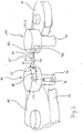
- a first reference device which serves as transmitting device 14 is formed, a contact body 10 and an adjoining Base 12, which are cylindrical in the example shown, wherein the Diameter of the body 12 is greater.
- the contact body 10 is manufactured precisely and is located on the peripheral surface of a likewise precisely manufactured pulley 18th on, while the main body 12 with a part of its underside at the top Face of the pulley 18 abuts.
- the transmitting device 14 is doing in known manner attached to the pulley 18 so that they are in solid and defined spatial relationship with the belt pulley 18, wherein the Drehsymmetrieachse the transmitting device 14 as closely as possible parallel to the Rotary axis 15 of the pulley 18 should be.
- the transmitting device 14 by means of built-permanent magnets, through Belt tension or held in place with adhesive rubber, in the latter case may be advantageous to first fix a pressure spring with the adhesive rubber, which in turn is able to transmit the transmitting device 14 during the To fix alignment process.
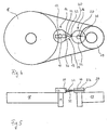
- the pulley 18 is by means of a belt 13 with a second pulley 19th connected, which in turn is rotatably mounted about a rotation axis 17.
- One as Target device 16 formed second reference device comprises in similar As the transmitting device 14 a system body 20, to which a Base body 22 connects upwards, both bodies formed as a circular cylinder are and the diameter of the base body 22 is greater than that of the contact body 20. The target device 16 is brought to bear against the second pulley 19, this being analogous to the attachment of the transmitter body 14 to the first Pulley 18 is done.
- the rotational symmetry axis of the target device 16 is intended to be as exactly parallel to the axis of rotation 17 of the pulley 19 are.
- Pulleys 18 and 19 are aligned so that on the one hand their axes of rotation 15 and 17 are exactly parallel to each other and also the pulleys 18 and 19 are possible in one plane, i. are also aligned axially with each other.
- the transmitting device 14 is provided with a light source 24, which in the example shown is provided in the axial direction in the plant body 10. It is about preferably around a semiconductor laser whose light falls on a deflection mirror 100, it reflects in the radial direction in the body 12 to an exit point 30. Instead, however, the light source in the base body 12 in the radial direction be provided, in which case the deflection mirror 100 is dispensable.
- a switch 104 is shown, by means of which the Light source 24 is turned on for the performance of a measurement or again can be turned off.
- the emerging from the outlet opening 32 incident beam 32 is of im essential circular profile and can be either in collimated or approximately collimated shape, i. with substantially parallel rays, or in convergent form, in the latter case a corresponding focusing optics is provided.
- the incident beam 32 hits in one Impact point 40 on a reflector 42, on the circular cylindrical outer surface of the Base 22 of the target device 16 is provided.
- the impact point has 40 typically a diameter of a few mm.
- the reflector 42 is in a direction to the longitudinal symmetry line of the target device, i. one in the context of the application error to the axis of rotation 17 of the pulley 19, vertical plane as a convex curved surface with a constant radius of curvature formed while the reflector 42 in the direction perpendicular thereto, i. in the direction the axis of symmetry of the target device 16 and the axis of rotation 17 of the Pulley 19, flat.
- the reflector 42 formed partially permeable, so that on the one hand a part of the incident Light beam 32 is reflected back in the direction of the transmitting device 14, while another part is transmitted as beam 44 through the reflector 42 and in an impact point 50 from the inside to the reflector 42 opposite Outside of the main body 22 of the target device 16 strikes.
- the main body 22 the target device 16 is in the region between the reflector 42 and the Impact point 50 hollow or formed of transparent material.
- the area around the Impact point 50 is preferably designed as a ground glass to a Observe the point of impact 50 from the outside.
- a marking line 52 is attached, as in the circumferential direction of the main body 22 extending straight line is formed and in the illustration of Fig. 1 thus extends substantially horizontally.
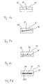
- the marking lines 38 and 52 are mounted so that when exactly parallel aligned pulleys 18 and 19, i. with exactly parallel aligned Transmitting device 14 and target device 16, and in addition in the same plane located pulleys 18 and 19 of the transmitted beam 44 exactly on the Marking line 52 impinges and the reflected flat beam 35 exactly on the Marking line 38 falls. Deviations from this ideal orientation make themselves by corresponding deviations of the impact point 50 from the mark 52 and the impact point of the flat beam 35 from the mark 38 noticeable. So leads For example, an axial offset of the discs 18 and 19 to a corresponding vertical displacement of the point of impingement 50 of the transmitted beam 44. A such situation is shown schematically in Figs. 5, 7 and 8a.
- a rotation between the transmitting device 14 and the target device 16 to a to the connecting line between the discs 18 and 19 parallel axis (“Roll offset”) causes the line or band-like impact area 39 of the reflected flat beam 35 on the outer surface of the base body 12 with respect to the Marking line 38 is rotated by a corresponding angle (see Fig. 8b).
- misalignments described may occur in combination, with the then superimpose described effects, in which case, for example, at a combined roll and pitch offset the impact area 39 of the reflected Flat beam 35 with respect to the marking line 38 both twisted and parallel is moved.
- the adjustment of the positions of the pulleys 18 and 19 can now characterized take place that the position of the pulleys 18 and 19 is changed until the Impact point 50 of the transmitted beam 44 is located on the marking line 52 and the impact area 39 of the flat jet 34 is located centrally on the marking line 38.
- the impact area 39 of the reflected flat beam 35 on the Base body 12 broaden due to the divergence of the flat jet 35, although the Opening angle of the flat jet 35 remains the same.
- the incident beam 32 in a similar manner Providing a suitable focusing optics (not shown) in the base body 12 be convergent, the impact point 40 in the convergent Range, i. before the focus of the beam 32, must lie.
- the Distance between the transmitting device 14 and the target device 16 from a distant location of the impact point 40 to a focus near the point of impact 40 is increased, so the size of the impact point 40 due to the Convergence of the beam 32 from, which has the consequence that due to the curved Reflector 42, the opening angle of the flat jet 35, i. the angle between the marginal rays 34 and 36, reduced, whereby the divergence of the Flat beam 35 originating widening tendency of the impact area 39 can be counteracted or even compensated for this broadening tendency can be, if the convergence angle of the incident beam 32 accordingly is selected.
- FIG. 3 an alternative embodiment of the reflector 142 is shown at which the reflector 142 of the base body 122 of the target device 116 is not partially transparent, but is designed to be fully reflective.
- the role of the reflected Beam 44 and the impact point 50 from the above Embodiment takes here the incident beam 32 and its impact point 40 on the reflector, wherein the reflector 142 with a circumferential direction extending straight marking line 152 is provided in accordance with FIG. 3 in horizontal direction.
- the marking line 152 is narrower than that Diameter of the impact point 40 is formed and forms a non-reflective Area within the reflector 142.
- the information regarding the axial displacement can be derived directly from the shape of the Impact region 39 are determined, the occurrence of two separate Impact areas 39A and 39B indicate that there is no axial offset while the Occurrence of a single, uninterrupted impact area 39 means that a Axial displacement is present because then the point of impingement 40 not on the marking line 152 lies.
- Both the described embodiments with partially transparent reflector as well the described embodiments with fully reflective reflector provide the Advantage that the operator with the entire measurement information with respect to the alignment can catch a glimpse without, for example, having to turn his head.
- the main body 22 of the target device 16 can be realized, for example be that a body of transparent material, such as Plexiglas, im Area of the reflector is provided with a partially or fully reflecting layer, while the area of the point of impact of the transmitted beam by corresponding Surface treatment, such as roughening, as a diffusing screen is trained.
- a body of transparent material such as Plexiglas
- im Area of the reflector is provided with a partially or fully reflecting layer, while the area of the point of impact of the transmitted beam by corresponding Surface treatment, such as roughening, as a diffusing screen is trained.
- the gauge depends on different sizing of the belt drive can be adjusted. It is possible on the circumference of the main body a For example, three or four times combination of partial mirrors and associated Marking line 52, wherein the main body a. six- or octagonal basic shape receives.
Landscapes
- Physics & Mathematics (AREA)
- General Physics & Mathematics (AREA)
- Length Measuring Devices By Optical Means (AREA)
- Optical Elements Other Than Lenses (AREA)
Claims (25)
- Agencement pour évaluer l'alignement d'axes remarquables (15, 17) et la position axiale d'un premier (18) et d'un deuxième corps (19) l'un par rapport à l'autre, avec un premier (14) et un deuxième dispositif de référence (16, 116), qui peuvent être amenés en relation spatiale fixe par rapport à l'axe remarquable respectif sur le premier corps ou sur le deuxième corps, le premier dispositif de référence étant réalisé pour émettre un faisceau lumineux (32) et étant pourvu d'un premier marquage (38) et le deuxième dispositif de référence (16, 116) présentant un réflecteur (42, 142) et un deuxième marquage (52, 152), caractérisé en ce que le réflecteur (42, 142) a une forme convexe en coupe avec un plan perpendiculaire à l'axe remarquable (17) du deuxième corps (19).
- Agencement selon la revendication 1, caractérisé en ce que le réflecteur (42, 142) est plan dans la direction parallèle à l'axe remarquable (17) du deuxième corps (19).
- Agencement selon la revendication 1 ou 2, caractérisé en ce que le réflecteur (42, 142) a une courbure convexe continue en coupe avec le plan perpendiculaire à l'axe remarquable (17) du deuxième corps (19).
- Agencement selon la revendication 3, caractérisé en ce que le rayon de courbure est constant.
- Agencement selon la revendication 4, caractérisé en ce que le réflecteur (42, 142) est réalisé sous la forme d'une surface cylindrique circulaire.
- Agencement selon l'une quelconque des revendications 1 à 5, caractérisé en ce que le deuxième marquage (152) est réalisé sur le réflecteur (142).
- Agencement selon la revendication 6, caractérisé en ce que le deuxième marquage (152) est réalisé sous la forme d'une région non réfléchissante.
- Agencement selon la revendication 6 ou 7, caractérisé en ce que le deuxième marquage (152) est réalisé sous la forme d'une ligne droite, qui s'étend approximativement dans un plan perpendiculaire à l'axe remarquable (17) du deuxième corps (19).
- Agencement selon l'une quelconque des revendications 6 à 8, caractérisé en ce que le deuxième marquage (152) est disposé de telle sorte, et son étendue dans la direction de l'axe remarquable (17) du deuxième corps (19) est choisie de telle sorte que sans décalage axial du premier (18) et du deuxième corps l'un par rapport à l'autre, le point d'incidence (40) du faisceau (32) émis par le premier dispositif de référence (14) sur le réflecteur (142) soit coupé au milieu par le deuxième marquage.
- Agencement pour évaluer l'alignement d'axes remarquables (15, 17) et la position axiale d'un premier (18) corps et d'un deuxième corps (19) l'un par rapport à l'autre, avec un premier (14) et un deuxième dispositif de référence (16), qui peuvent être amenés en relation spatiale fixe par rapport à l'axe remarquable respectif sur le premier corps ou sur le deuxième corps, le premier dispositif de référence étant réalisé pour émettre un faisceau lumineux (32) et étant pourvu d'un premier marquage (38) et le deuxième dispositif de référence présentant un réflecteur (42) et un deuxième marquage (52), caractérisé en ce que le réflecteur (42) est réalisé de manière semi-transparente, une partie (35) du faisceau lumineux (32) étant réfléchie dans la région du premier marquage (38) et une partie (44) du faisceau lumineux (32) étant transmise dans la région du deuxième marquage (52).
- Agencement selon la revendication 10, caractérisé en ce que le premier marquage (38) est prévu à proximité du point de sortie du faisceau lumineux (30) hors du premier dispositif de référence (14).
- Agencement selon la revendication 11, caractérisé en ce que le deuxième marquage (52) est disposé à l'opposé par rapport au réflecteur (42).
- Agencement selon la revendication 12, caractérisé en ce que la région du deuxième marquage (52) pour le faisceau lumineux transmis (44) est réalisée sous la forme d'un écran dépoli, de sorte que le spot lumineux (50) produit par le faisceau lumineux transmis soit visible de l'extérieur.
- Agencement selon l'une quelconque des revendications précédentes, caractérisé en ce que le premier (38) et le deuxième marquage (52) sont réalisés chacun sous la forme d'une ligne droite, qui s'étend approximativement dans un plan perpendiculaire à l'axe remarquable (15, 17) du premier (18), respectivement du deuxième corps (19).
- Agencement selon la revendication 14, caractérisé en ce que la région du premier marquage (38) est réalisée sous la forme d'une surface cylindrique, l'axe du cylindre étant orienté approximativement parallèlement à l'axe remarquable (15) du premier corps (18).
- Agencement selon l'une quelconque des revendications 10 à 14, caractérisé en ce que le réflecteur (42) a une forme convexe en coupe avec un plan perpendiculaire à l'axe remarquable (17) du deuxième corps (19).
- Agencement selon l'une quelconque des revendications précédentes, caractérisé en ce que le faisceau lumineux (32) émis par le premier dispositif de référence (14) a une forme convergente.
- Agencement selon l'une quelconque des revendications précédentes, caractérisé en ce que le faisceau lumineux (32) est de la lumière laser.
- Agencement selon l'une quelconque des revendications précédentes, caractérisé en ce que le faisceau lumineux (32) est émis dans un plan qui est perpendiculaire à l'axe remarquable (15) du premier corps (18).
- Agencement selon l'une quelconque des revendications précédentes, caractérisé en ce que le deuxième dispositif de référence (16) est réalisé de telle sorte que le faisceau (35) réfléchi par le réflecteur (42) se situe au moins approximativement dans le même plan que le faisceau émis (32).
- Agencement' selon l'une quelconque des revendications précédentes, caractérisé en ce que le premier (18) et le deuxième corps (19) sont montés à rotation et que l'axe remarquable (15, 17) est dans chaque cas l'axe de rotation.
- Agencement selon la revendication 21, caractérisé en ce que le premier et le deuxième corps sont deux poulies (18, 19).
- Agencement selon la revendication 22, caractérisé en ce que le premier (14) et le deuxième dispositif de référence (16) sont à chaque fois réalisés pour s'appliquer contre une face frontale de la première (18) ou de la deuxième poulie (19).
- Procédé pour évaluer l'alignement d'axes remarquables (15, 17) et la position axiale d'un premier (18) et d'un deuxième corps (19) l'un par rapport à l'autre, un premier (14) et un deuxième dispositif de référence (16) pouvant être amenés en relation fixe par rapport à l'axe remarquable respectif sur le premier corps ou sur le deuxième corps, un faisceau lumineux (32) étant émis par le premier dispositif de référence sur un réflecteur (42) prévu sur le deuxième dispositif de référence, lequel réflecteur réfléchit une partie (35) du faisceau lumineux dans la région d'un premier marquage (38) sur le premier dispositif de référence et transmet une partie (44) du faisceau lumineux dans la région d'un deuxième marquage (52) sur le deuxième dispositif de référence, et l'alignement étant évalué à l'aide de la position du spot lumineux produit par le faisceau lumineux dans la région du premier, respectivement du deuxième marquage.
- Procédé pour évaluer l'alignement d'axes remarquables (15, 17) et la position axiale d'un premier (18) et d'un deuxième corps (19) l'un par rapport à l'autre, un premier (14) et un deuxième dispositif de référence (16, 116) pouvant être amenés en relation fixe par rapport à l'axe remarquable respectif sur le premier corps ou sur le deuxième corps, un faisceau lumineux (32) étant émis par le premier dispositif de référence sur un réflecteur (42, 142) prévu sur le deuxième dispositif de référence, lequel a une forme convexe en coupe avec un plan perpendiculaire à l'axe remarquable (17) du deuxième corps (19) et réfléchit au moins une partie (35) du faisceau lumineux (32) dans la région d'un premier marquage (38) sur le premier dispositif de référence, et l'alignement étant évalué au moins en partie à l'aide de la position du spot lumineux produit par le faisceau lumineux dans la région du premier marquage.
Applications Claiming Priority (2)
| Application Number | Priority Date | Filing Date | Title |
|---|---|---|---|
| DE10064122 | 2000-12-21 | ||
| DE10064122A DE10064122A1 (de) | 2000-12-21 | 2000-12-21 | Anordnung und Verfahren zum Ermitteln der Ausrichtung zweier Körper relativ zueinander |
Publications (2)
| Publication Number | Publication Date |
|---|---|
| EP1233247A1 EP1233247A1 (fr) | 2002-08-21 |
| EP1233247B1 true EP1233247B1 (fr) | 2005-07-27 |
Family
ID=7668348
Family Applications (1)
| Application Number | Title | Priority Date | Filing Date |
|---|---|---|---|
| EP01130412A Expired - Lifetime EP1233247B1 (fr) | 2000-12-21 | 2001-12-20 | Evaluation de l'alignement respectif de deux corps ( poulies ) avec un réflecteur convexe ou semi transparent |
Country Status (3)
| Country | Link |
|---|---|
| EP (1) | EP1233247B1 (fr) |
| AT (1) | ATE300724T1 (fr) |
| DE (2) | DE10064122A1 (fr) |
Families Citing this family (3)
| Publication number | Priority date | Publication date | Assignee | Title |
|---|---|---|---|---|
| CN102003949A (zh) * | 2010-10-29 | 2011-04-06 | 苏州工业园区高登威科技有限公司 | 内孔同心度检测装置 |
| DE102013216172A1 (de) * | 2013-08-14 | 2015-03-12 | Bayerische Motoren Werke Aktiengesellschaft | Scharnierfluchtprüfeinrichtung |
| DE102014207118A1 (de) | 2014-04-14 | 2015-10-15 | Prüftechnik Dieter Busch AG | Verfahren und Meßsystem zum Ermitteln der Ausrichtung einer ersten Riemenscheibe eines Riemenantriebs in Bezug auf eine zweite Riemenscheibe des Riemenantriebs |
Family Cites Families (1)
| Publication number | Priority date | Publication date | Assignee | Title |
|---|---|---|---|---|
| US6031616A (en) * | 1999-05-25 | 2000-02-29 | Seiffert; Russell W. | Laser pulley alignment system |
-
2000
- 2000-12-21 DE DE10064122A patent/DE10064122A1/de not_active Withdrawn
-
2001
- 2001-12-20 EP EP01130412A patent/EP1233247B1/fr not_active Expired - Lifetime
- 2001-12-20 DE DE50106882T patent/DE50106882D1/de not_active Expired - Lifetime
- 2001-12-20 AT AT01130412T patent/ATE300724T1/de not_active IP Right Cessation
Also Published As
| Publication number | Publication date |
|---|---|
| ATE300724T1 (de) | 2005-08-15 |
| EP1233247A1 (fr) | 2002-08-21 |
| DE10064122A1 (de) | 2002-11-21 |
| DE50106882D1 (de) | 2005-09-01 |
Similar Documents
| Publication | Publication Date | Title |
|---|---|---|
| EP2120025B1 (fr) | Dispositif de capteur optique destiné à la détection de lumière ambiante | |
| DE102013208649B4 (de) | Optischer Winkeldetektor mit Strahlformungselement | |
| DE10132769C1 (de) | Verfahren und Messeinrichtung zur Vermessung eines Zweiradrahmens | |
| CH640937A5 (de) | Vorrichtung zur beruehrungslosen messung der konturform von gegenstaenden. | |
| DE19537812C1 (de) | Instrument zum Bearbeiten der Oberfläche von Teilen in technischen Hohlräumen | |
| DE2241366A1 (de) | Einrichtung zur feststellung der abweichung der lage eines gleises von seiner soll-lage | |
| DE102004005932A1 (de) | Fahrzeugscheinwerfer und Lichtaussendemodul | |
| EP1118494A2 (fr) | Procédé pour aligner un capteur dans un système de commande de vitesse adaptatif dans un véhicule | |
| DE2633391A1 (de) | Optische anordnung zur erzeugung von lichtstrahlen, die genau im rechten winkel zueinander stehen | |
| EP3569976B1 (fr) | Tête de mesure de rugosité, dispositif avec ladite tête de mesure et utilisation correspondante | |
| EP1292805B1 (fr) | Dispositif de mesure destine a la detection de dimensions d'eprouvettes | |
| DE69203259T2 (de) | Apparat zum Abtasten von Gegenständen in Blattform. | |
| DE10325443A1 (de) | Interferometrische Messvorrichtung | |
| DE102011007459B4 (de) | Optische Längenmesseinrichtung | |
| EP0408920A2 (fr) | Dispositif pour engendrer un rideau lumineux | |
| DE19941030C1 (de) | Laseranordnung für ein mehrstrahliges Laserrichtgerät | |
| EP1233247A1 (fr) | Evaluation de l'alignement respectif de deux corps ( poulies ) avec un réflecteur convexe ou semi transparent | |
| DE10335207A1 (de) | Visiereinrichtung und Vorrichtung mit einer kontaktlos oder kontaktbehaftet einsetzbaren Mess-, Arbeits- und/oder Wirkeinrichtung | |
| DE102010041330A1 (de) | Optische Positionsmessvorrichtung | |
| DE2200092C3 (de) | Optische Lesevorrichtung zur Abtastung von Codemarken auf Gegenständen | |
| EP1176407A2 (fr) | Dispositif et méthode pour la mesure de température dans l'infrarouge | |
| DE2518828C3 (de) | Lichtschranke | |
| DE10062841B4 (de) | Lichtstrahlenempfänger für Laserpositioniergeräte | |
| EP4350303A1 (fr) | Procédé d'application d'un corps de mesure sur une surface d'un rail de guidage linéaire, rail de mesure pour un codeur linéaire et codeur linéaire | |
| EP2653883B1 (fr) | Capteur optique |
Legal Events
| Date | Code | Title | Description |
|---|---|---|---|
| PUAI | Public reference made under article 153(3) epc to a published international application that has entered the european phase |
Free format text: ORIGINAL CODE: 0009012 |
|
| AK | Designated contracting states |
Kind code of ref document: A1 Designated state(s): AT BE CH CY DE DK ES FI FR GB GR IE IT LI LU MC NL PT SE TR |
|
| AX | Request for extension of the european patent |
Free format text: AL;LT;LV;MK;RO;SI |
|
| 17P | Request for examination filed |
Effective date: 20030121 |
|
| AKX | Designation fees paid |
Designated state(s): AT BE CH CY DE DK ES FI FR GB GR IE IT LI LU MC NL PT SE TR |
|
| GRAP | Despatch of communication of intention to grant a patent |
Free format text: ORIGINAL CODE: EPIDOSNIGR1 |
|
| GRAL | Information related to payment of fee for publishing/printing deleted |
Free format text: ORIGINAL CODE: EPIDOSDIGR3 |
|
| GRAS | Grant fee paid |
Free format text: ORIGINAL CODE: EPIDOSNIGR3 |
|
| GRAA | (expected) grant |
Free format text: ORIGINAL CODE: 0009210 |
|
| AK | Designated contracting states |
Kind code of ref document: B1 Designated state(s): AT BE CH CY DE DK ES FI FR GB GR IE IT LI LU MC NL PT SE TR |
|
| PG25 | Lapsed in a contracting state [announced via postgrant information from national office to epo] |
Ref country code: IT Free format text: LAPSE BECAUSE OF FAILURE TO SUBMIT A TRANSLATION OF THE DESCRIPTION OR TO PAY THE FEE WITHIN THE PRE;WARNING: LAPSES OF ITALIAN PATENTS WITH EFFECTIVE DATE BEFORE 2007 MAY HAVE OCCURRED AT ANY TIME BEFORE 2007. THE CORRECT EFFECTIVE DATE MAY BE DIFFERENT FROM THE ONE RECORDED.SCRIBED TIME-LIMIT Effective date: 20050727 Ref country code: ES Free format text: LAPSE BECAUSE OF FAILURE TO SUBMIT A TRANSLATION OF THE DESCRIPTION OR TO PAY THE FEE WITHIN THE PRESCRIBED TIME-LIMIT Effective date: 20050727 Ref country code: NL Free format text: LAPSE BECAUSE OF FAILURE TO SUBMIT A TRANSLATION OF THE DESCRIPTION OR TO PAY THE FEE WITHIN THE PRESCRIBED TIME-LIMIT Effective date: 20050727 Ref country code: TR Free format text: LAPSE BECAUSE OF FAILURE TO SUBMIT A TRANSLATION OF THE DESCRIPTION OR TO PAY THE FEE WITHIN THE PRESCRIBED TIME-LIMIT Effective date: 20050727 Ref country code: FI Free format text: LAPSE BECAUSE OF FAILURE TO SUBMIT A TRANSLATION OF THE DESCRIPTION OR TO PAY THE FEE WITHIN THE PRESCRIBED TIME-LIMIT Effective date: 20050727 Ref country code: IE Free format text: LAPSE BECAUSE OF FAILURE TO SUBMIT A TRANSLATION OF THE DESCRIPTION OR TO PAY THE FEE WITHIN THE PRESCRIBED TIME-LIMIT Effective date: 20050727 |
|
| REG | Reference to a national code |
Ref country code: GB Ref legal event code: FG4D Free format text: NOT ENGLISH |
|
| REG | Reference to a national code |
Ref country code: CH Ref legal event code: EP |
|
| REG | Reference to a national code |
Ref country code: IE Ref legal event code: FG4D Free format text: LANGUAGE OF EP DOCUMENT: GERMAN |
|
| REF | Corresponds to: |
Ref document number: 50106882 Country of ref document: DE Date of ref document: 20050901 Kind code of ref document: P |
|
| PG25 | Lapsed in a contracting state [announced via postgrant information from national office to epo] |
Ref country code: DK Free format text: LAPSE BECAUSE OF FAILURE TO SUBMIT A TRANSLATION OF THE DESCRIPTION OR TO PAY THE FEE WITHIN THE PRESCRIBED TIME-LIMIT Effective date: 20051027 Ref country code: GR Free format text: LAPSE BECAUSE OF FAILURE TO SUBMIT A TRANSLATION OF THE DESCRIPTION OR TO PAY THE FEE WITHIN THE PRESCRIBED TIME-LIMIT Effective date: 20051027 Ref country code: SE Free format text: LAPSE BECAUSE OF FAILURE TO SUBMIT A TRANSLATION OF THE DESCRIPTION OR TO PAY THE FEE WITHIN THE PRESCRIBED TIME-LIMIT Effective date: 20051027 |
|
| GBT | Gb: translation of ep patent filed (gb section 77(6)(a)/1977) |
Effective date: 20051020 |
|
| PG25 | Lapsed in a contracting state [announced via postgrant information from national office to epo] |
Ref country code: AT Free format text: LAPSE BECAUSE OF NON-PAYMENT OF DUE FEES Effective date: 20051220 Ref country code: CY Free format text: LAPSE BECAUSE OF FAILURE TO SUBMIT A TRANSLATION OF THE DESCRIPTION OR TO PAY THE FEE WITHIN THE PRESCRIBED TIME-LIMIT Effective date: 20051220 |
|
| PG25 | Lapsed in a contracting state [announced via postgrant information from national office to epo] |
Ref country code: PT Free format text: LAPSE BECAUSE OF FAILURE TO SUBMIT A TRANSLATION OF THE DESCRIPTION OR TO PAY THE FEE WITHIN THE PRESCRIBED TIME-LIMIT Effective date: 20051227 |
|
| PG25 | Lapsed in a contracting state [announced via postgrant information from national office to epo] |
Ref country code: BE Free format text: LAPSE BECAUSE OF NON-PAYMENT OF DUE FEES Effective date: 20051231 Ref country code: LU Free format text: LAPSE BECAUSE OF NON-PAYMENT OF DUE FEES Effective date: 20051231 Ref country code: LI Free format text: LAPSE BECAUSE OF NON-PAYMENT OF DUE FEES Effective date: 20051231 Ref country code: MC Free format text: LAPSE BECAUSE OF NON-PAYMENT OF DUE FEES Effective date: 20051231 Ref country code: CH Free format text: LAPSE BECAUSE OF NON-PAYMENT OF DUE FEES Effective date: 20051231 |
|
| NLV1 | Nl: lapsed or annulled due to failure to fulfill the requirements of art. 29p and 29m of the patents act | ||
| REG | Reference to a national code |
Ref country code: IE Ref legal event code: FD4D |
|
| ET | Fr: translation filed | ||
| PLBE | No opposition filed within time limit |
Free format text: ORIGINAL CODE: 0009261 |
|
| STAA | Information on the status of an ep patent application or granted ep patent |
Free format text: STATUS: NO OPPOSITION FILED WITHIN TIME LIMIT |
|
| 26N | No opposition filed |
Effective date: 20060428 |
|
| REG | Reference to a national code |
Ref country code: CH Ref legal event code: PL |
|
| BERE | Be: lapsed |
Owner name: PRUFTECHNIK DIETER BUSCH A.G. Effective date: 20051231 |
|
| REG | Reference to a national code |
Ref country code: FR Ref legal event code: PLFP Year of fee payment: 15 |
|
| REG | Reference to a national code |
Ref country code: FR Ref legal event code: PLFP Year of fee payment: 16 |
|
| REG | Reference to a national code |
Ref country code: FR Ref legal event code: PLFP Year of fee payment: 17 |
|
| PGFP | Annual fee paid to national office [announced via postgrant information from national office to epo] |
Ref country code: GB Payment date: 20181219 Year of fee payment: 18 Ref country code: FR Payment date: 20181218 Year of fee payment: 18 |
|
| PGFP | Annual fee paid to national office [announced via postgrant information from national office to epo] |
Ref country code: DE Payment date: 20181220 Year of fee payment: 18 |
|
| REG | Reference to a national code |
Ref country code: DE Ref legal event code: R119 Ref document number: 50106882 Country of ref document: DE |
|
| GBPC | Gb: european patent ceased through non-payment of renewal fee |
Effective date: 20191220 |
|
| PG25 | Lapsed in a contracting state [announced via postgrant information from national office to epo] |
Ref country code: DE Free format text: LAPSE BECAUSE OF NON-PAYMENT OF DUE FEES Effective date: 20200701 Ref country code: GB Free format text: LAPSE BECAUSE OF NON-PAYMENT OF DUE FEES Effective date: 20191220 Ref country code: FR Free format text: LAPSE BECAUSE OF NON-PAYMENT OF DUE FEES Effective date: 20191231 |