EP1233434A2 - Taststrutur für elektronische, elektrische oder mechanische Anwendungen - Google Patents
Taststrutur für elektronische, elektrische oder mechanische Anwendungen Download PDFInfo
- Publication number
- EP1233434A2 EP1233434A2 EP02000284A EP02000284A EP1233434A2 EP 1233434 A2 EP1233434 A2 EP 1233434A2 EP 02000284 A EP02000284 A EP 02000284A EP 02000284 A EP02000284 A EP 02000284A EP 1233434 A2 EP1233434 A2 EP 1233434A2
- Authority
- EP
- European Patent Office
- Prior art keywords
- pushbutton
- component
- elastically deformable
- pushbutton structure
- deformable component
- Prior art date
- Legal status (The legal status is an assumption and is not a legal conclusion. Google has not performed a legal analysis and makes no representation as to the accuracy of the status listed.)
- Granted
Links
- 238000002347 injection Methods 0.000 claims abstract description 3
- 239000007924 injection Substances 0.000 claims abstract description 3
- 239000000463 material Substances 0.000 claims description 9
- PPBRXRYQALVLMV-UHFFFAOYSA-N Styrene Chemical compound C=CC1=CC=CC=C1 PPBRXRYQALVLMV-UHFFFAOYSA-N 0.000 claims description 4
- 238000007789 sealing Methods 0.000 claims description 3
- -1 ethylene-butylene Chemical group 0.000 claims description 2
- 230000000379 polymerizing effect Effects 0.000 claims description 2
- 229920002725 thermoplastic elastomer Polymers 0.000 claims description 2
- 229920003052 natural elastomer Polymers 0.000 claims 1
- 229920001194 natural rubber Polymers 0.000 claims 1
- 230000002093 peripheral effect Effects 0.000 claims 1
- 229920003051 synthetic elastomer Polymers 0.000 claims 1
- 239000005061 synthetic rubber Substances 0.000 claims 1
- 239000004033 plastic Substances 0.000 description 6
- 230000012447 hatching Effects 0.000 description 3
- 230000008595 infiltration Effects 0.000 description 3
- 238000001764 infiltration Methods 0.000 description 3
- 238000001746 injection moulding Methods 0.000 description 3
- 230000003068 static effect Effects 0.000 description 3
- XLYOFNOQVPJJNP-UHFFFAOYSA-N water Substances O XLYOFNOQVPJJNP-UHFFFAOYSA-N 0.000 description 3
- 229920001971 elastomer Polymers 0.000 description 2
- 238000000465 moulding Methods 0.000 description 2
- 239000005060 rubber Substances 0.000 description 2
- 239000000243 solution Substances 0.000 description 2
- 229920001935 styrene-ethylene-butadiene-styrene Polymers 0.000 description 2
- 239000006185 dispersion Substances 0.000 description 1
- 230000000694 effects Effects 0.000 description 1
- 239000002991 molded plastic Substances 0.000 description 1
- 239000007787 solid Substances 0.000 description 1
- 238000005406 washing Methods 0.000 description 1
Images


Classifications
-
- H—ELECTRICITY
- H01—ELECTRIC ELEMENTS
- H01H—ELECTRIC SWITCHES; RELAYS; SELECTORS; EMERGENCY PROTECTIVE DEVICES
- H01H13/00—Switches having rectilinearly-movable operating part or parts adapted for pushing or pulling in one direction only, e.g. push-button switch
- H01H13/02—Details
- H01H13/04—Cases; Covers
- H01H13/06—Dustproof, splashproof, drip-proof, waterproof or flameproof casings
-
- H—ELECTRICITY
- H01—ELECTRIC ELEMENTS
- H01H—ELECTRIC SWITCHES; RELAYS; SELECTORS; EMERGENCY PROTECTIVE DEVICES
- H01H11/00—Apparatus or processes specially adapted for the manufacture of electric switches
- H01H2011/0081—Apparatus or processes specially adapted for the manufacture of electric switches using double shot moulding, e.g. for forming elastomeric sealing elements on form stable casing
-
- H—ELECTRICITY
- H01—ELECTRIC ELEMENTS
- H01H—ELECTRIC SWITCHES; RELAYS; SELECTORS; EMERGENCY PROTECTIVE DEVICES
- H01H21/00—Switches operated by an operating part in the form of a pivotable member acted upon directly by a solid body, e.g. by a hand
- H01H21/02—Details
- H01H21/18—Movable parts; Contacts mounted thereon
- H01H21/22—Operating parts, e.g. handle
- H01H21/24—Operating parts, e.g. handle biased to return to normal position upon removal of operating force
Definitions
- the present invention relates to a pushbutton structure for electronic, electrical and/or mechanical applications.
- the described solution has however the drawback of difficult acceptability if the pushbutton has also to have an aesthetic function. This is the case with pushbuttons for household electrical appliances such as refrigerators, washing machines,conventional or microwave ovens etc. in which functionality (in the strict sense of this term) must be associated with appearance, i.e. with the aesthetics of the product in which the pushbuttons are important components.
- the main object of the invention is to provide a pushbutton structure which associates unexceptionable functionality, especially in terms of its sealing, with a pleasant appearance.
- Another object of the present invention is to provide a simple, reliable and compact pushbutton structure.
- the reference numeral 1 indicates overall a conventional front panel behind which a conventional electro-electronic circuit 2, for example a printed circuit is situated, comprising a schematically represented switch, for example an electronic switch 3, which is to be operated by a pushbutton structure, indicated overall by 4.
- the panel 1 presents an outer component, for example decorative, and an inner component provided with a seat 1A for snap-engaging the pushbutton structure 4, the operated part 4A of which emerges from holes 1B of the front panel 1.
- the pushbutton structure 4 is co-injection moulded or co-moulded from plastic material definable as rigid (for example ABS) or from rubbery material (for example thermoplastic rubber for injection moulding, particularly SEBS rubber obtained by polymerizing styrene and ethylene-butylene blocks), with the result that the structure is in one piece.
- the rigid plastic component (indicated by parallel line hatching) comprises an apron 4B connected by a bridge 14 ( Figure 1) to the operated part 4A comprising a base flange 4C and an axial finger 4D facing the switch 3 on which it is intended to act.
- the elastic component comprises an inner groove 5A into which there extends the flange 4C of the part 4A.
- the elastic component 5 comprises a groove 5B which is open upwards, i.e. towards the front panel 1.
- the elastic component 5 comprises a surrounding flange 5C provided with appendices 5D and 5E for engagement with or in corresponding seats or passages 4E and 4F of the part 4B (as already stated this is joined to the part 4A by the bridge 14).
- the flange 5C presents, respectively facing upwards and outwards, annular seal rims 5F and 5G, preferably of triangular section, which are intended to cooperate - for sealing purposes - with the seat 1A and with the front panel 1.
- At least part of the rubbery material of the component 5 is preferably chosen transparent or translucent for a reason which will be explained hereinafter.
- the rigid plastic component i.e. the component 4
- a light source 11 for example an LED
- the component 4 presents, aligned with the light source 11 and with the passage 10, a light guide 12 in the form of a cylindrical or frusto-conical appendix facing and surrounding said source.
- the movement of the component 4 (during its operation and return) is substantially a rocking movement (arrow Z) about the bridge 14 and the fourth side 13 (that without the groove 5B) of the elastic component 5.
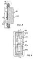
- Figure 3 is a simple variant of the embodiment of Figures 1 and 2.
- parts equal or corresponding to those of Figures 1 and 2 are indicated by the same reference numerals plus 100.
- the difference lies in the fact that the passage 10 occupied by the co-injected transparent or translucent rubbery component is not provided.
- the rigid plastic part 104 (which corresponds to that of Figures 1 and 2) is in fact solid, signifying that in this pushbutton structure, visibility of the state of the static switch 3 of the relative circuit is not required.
- Figures 4, 4A and 4B show another embodiment of the invention, providing a double pushbutton structure in the sense that the user can act on two members, each of which determines the passage of state of a different switch (static or non-static).
- parts equal or corresponding to those of Figure 1 are indicated by the same reference numerals plus 200.
- the rubbery component (again shown by cross hatching) indicated here by 205 is joined (by the effect of co-injection moulding or co-moulding) to two separate pushbutton components 204a and 204b both provided with an off-centre operating finger 204d (similar to the embodiments of Figures 2 and 3). Each of them can be operated independently of the other.
Landscapes
- Push-Button Switches (AREA)
- Switch Cases, Indication, And Locking (AREA)
- Control Of Vending Devices And Auxiliary Devices For Vending Devices (AREA)
- Adhesives Or Adhesive Processes (AREA)
- Pens And Brushes (AREA)
Applications Claiming Priority (2)
| Application Number | Priority Date | Filing Date | Title |
|---|---|---|---|
| ITMI20010302 ITMI20010302A1 (it) | 2001-02-14 | 2001-02-14 | Costruzione di pulsanti per applicazioni elettroniche elettriche e/o meccaniche |
| ITMI010302 | 2001-02-14 |
Publications (3)
| Publication Number | Publication Date |
|---|---|
| EP1233434A2 true EP1233434A2 (de) | 2002-08-21 |
| EP1233434A3 EP1233434A3 (de) | 2004-06-16 |
| EP1233434B1 EP1233434B1 (de) | 2014-01-08 |
Family
ID=11446881
Family Applications (1)
| Application Number | Title | Priority Date | Filing Date |
|---|---|---|---|
| EP20020000284 Expired - Lifetime EP1233434B1 (de) | 2001-02-14 | 2002-01-15 | Taststruktur für elektronische, elektrische oder mechanische Anwendungen |
Country Status (3)
| Country | Link |
|---|---|
| EP (1) | EP1233434B1 (de) |
| ES (1) | ES2445580T3 (de) |
| IT (1) | ITMI20010302A1 (de) |
Cited By (6)
| Publication number | Priority date | Publication date | Assignee | Title |
|---|---|---|---|---|
| WO2013067984A1 (de) * | 2011-11-10 | 2013-05-16 | Eao Automotive Gmbh & Co. Kg | Beleuchtetes, wasser- und staubdichtes schaltelement |
| EP1916686B1 (de) * | 2006-10-26 | 2013-08-07 | elobau GmbH & Co. KG | Taster |
| CN103681047A (zh) * | 2012-09-10 | 2014-03-26 | 光宝电子(广州)有限公司 | 按键及音响装置 |
| CN105144330A (zh) * | 2013-03-01 | 2015-12-09 | Zf腓德烈斯哈芬股份公司 | 按键开关帽 |
| WO2020028524A1 (en) * | 2018-07-31 | 2020-02-06 | Bose Corporation | Plunger interface |
| CN112750640A (zh) * | 2019-10-30 | 2021-05-04 | 比亚迪股份有限公司 | 电子设备及其外壳 |
Citations (2)
| Publication number | Priority date | Publication date | Assignee | Title |
|---|---|---|---|---|
| DE3312126A1 (de) | 1983-04-02 | 1984-10-11 | Ing. Gerhard Dekorsy GmbH, 7760 Radolfzell | Taste fuer ein in tastrichtung bewegbares schaltelement |
| DE19903838C1 (de) | 1999-02-01 | 2000-07-20 | Moeller Gmbh | Drucktaste |
Family Cites Families (5)
| Publication number | Priority date | Publication date | Assignee | Title |
|---|---|---|---|---|
| DE69133106T2 (de) * | 1990-10-30 | 2003-04-30 | Teikoku Tsushin Kogyo Co. Ltd., Kawasaki | Taste und Verfahren zur Herstellung der Taste |
| US5706168A (en) * | 1995-07-07 | 1998-01-06 | Itronix Corporation | Impact-resistant notebook computer having hard drive mounted on shock-isolating mounting bridge and impact attenuating covering |
| DE19953046A1 (de) * | 1998-11-09 | 2000-05-11 | Marquardt Gmbh | Elektrischer Schalter |
| JP4209546B2 (ja) * | 1999-02-26 | 2009-01-14 | 矢崎総業株式会社 | プッシュスイッチ構造 |
| EP1054420A1 (de) * | 1999-05-18 | 2000-11-22 | Molex Incorporated | Tastenfeld für ein elektrisches oder elektronisches Gerät sowie Verfahren zu dessen Herstellung |
-
2001
- 2001-02-14 IT ITMI20010302 patent/ITMI20010302A1/it unknown
-
2002
- 2002-01-15 ES ES02000284T patent/ES2445580T3/es not_active Expired - Lifetime
- 2002-01-15 EP EP20020000284 patent/EP1233434B1/de not_active Expired - Lifetime
Patent Citations (2)
| Publication number | Priority date | Publication date | Assignee | Title |
|---|---|---|---|---|
| DE3312126A1 (de) | 1983-04-02 | 1984-10-11 | Ing. Gerhard Dekorsy GmbH, 7760 Radolfzell | Taste fuer ein in tastrichtung bewegbares schaltelement |
| DE19903838C1 (de) | 1999-02-01 | 2000-07-20 | Moeller Gmbh | Drucktaste |
Cited By (13)
| Publication number | Priority date | Publication date | Assignee | Title |
|---|---|---|---|---|
| EP1916686B1 (de) * | 2006-10-26 | 2013-08-07 | elobau GmbH & Co. KG | Taster |
| US9368297B2 (en) | 2011-11-10 | 2016-06-14 | Eao Automotive Gmbh & Co. Kg | Illuminated, water- and dust-proof switching element |
| CN103946941A (zh) * | 2011-11-10 | 2014-07-23 | Eao汽车股份两合公司 | 照明、防水、防尘的开关元件 |
| JP2014532973A (ja) * | 2011-11-10 | 2014-12-08 | エーアーオー・アウトモティーフェ・ゲゼルシャフト・ミト・ベシュレンクテル・ハフツング・ウント・コンパニー・コマンデイトゲゼルシャフト | 防水及び防塵形のイルミネーションスイッチ要素 |
| WO2013067984A1 (de) * | 2011-11-10 | 2013-05-16 | Eao Automotive Gmbh & Co. Kg | Beleuchtetes, wasser- und staubdichtes schaltelement |
| CN103681047A (zh) * | 2012-09-10 | 2014-03-26 | 光宝电子(广州)有限公司 | 按键及音响装置 |
| CN103681047B (zh) * | 2012-09-10 | 2015-11-25 | 光宝电子(广州)有限公司 | 按键及音响装置 |
| CN105144330A (zh) * | 2013-03-01 | 2015-12-09 | Zf腓德烈斯哈芬股份公司 | 按键开关帽 |
| CN105144330B (zh) * | 2013-03-01 | 2017-11-14 | Zf 腓德烈斯哈芬股份公司 | 按键开关帽 |
| WO2020028524A1 (en) * | 2018-07-31 | 2020-02-06 | Bose Corporation | Plunger interface |
| JP2021532557A (ja) * | 2018-07-31 | 2021-11-25 | ボーズ・コーポレーションBose Corporation | プランジャインターフェース |
| JP7179153B2 (ja) | 2018-07-31 | 2022-11-28 | ボーズ・コーポレーション | プランジャインターフェース |
| CN112750640A (zh) * | 2019-10-30 | 2021-05-04 | 比亚迪股份有限公司 | 电子设备及其外壳 |
Also Published As
| Publication number | Publication date |
|---|---|
| EP1233434B1 (de) | 2014-01-08 |
| EP1233434A3 (de) | 2004-06-16 |
| ITMI20010302A1 (it) | 2002-08-14 |
| ES2445580T3 (es) | 2014-03-04 |
Similar Documents
| Publication | Publication Date | Title |
|---|---|---|
| US7087847B2 (en) | Elastomer keypad and bezel | |
| US6204459B1 (en) | Switching arrangement | |
| US8209868B2 (en) | Device with an illuminated button assembly | |
| US6737596B1 (en) | Integrated switch bank | |
| US7503193B2 (en) | Button apparatus and method of manufacture | |
| US4997998A (en) | Key cap for a keyboard | |
| US20110134627A1 (en) | Appliance doors having integrated lighting and controls | |
| JP2003249139A (ja) | 照光式押釦スイッチ用カバー部材 | |
| EP1233434A2 (de) | Taststrutur für elektronische, elektrische oder mechanische Anwendungen | |
| CN114829200B (zh) | 用于机动车的操作单元 | |
| US20060114128A1 (en) | Operating device for a domestic electrical appliance | |
| US5574253A (en) | Housing for an electrically powered appliance for personal use | |
| CN107773192B (zh) | 电器、具有面板的这种电器的结构和制造这种结构的方法 | |
| JP3069726B2 (ja) | キーボードスイッチ | |
| US6888079B2 (en) | Multifunctional pushbutton switch | |
| JPH0818249A (ja) | 光透過性操作ボタン一体型電気機器用ケース | |
| EP2012334B1 (de) | Integriertes Bedienfeld für Haushaltsanwendungen | |
| EP0878814A1 (de) | Staub- und Spritzwassergeschützte Schalteinheit | |
| KR20050081462A (ko) | 드럼 세탁기의 버튼 데코 설치구조 | |
| US20040089530A1 (en) | Multifunctional pushbutton switch | |
| US12016511B2 (en) | Domestic dishwasher | |
| KR200146982Y1 (ko) | 노브 일체형 구조의 판넬 | |
| KR100252668B1 (ko) | 스위치조작기구 | |
| CN100452265C (zh) | 控制器组装体 | |
| KR200220809Y1 (ko) | 박판 필름이 있는 케이스부품의 버튼장치(Button Device for Use with Case Unit Having Sheet Material) |
Legal Events
| Date | Code | Title | Description |
|---|---|---|---|
| PUAI | Public reference made under article 153(3) epc to a published international application that has entered the european phase |
Free format text: ORIGINAL CODE: 0009012 |
|
| AK | Designated contracting states |
Kind code of ref document: A2 Designated state(s): AT BE CH CY DE DK ES FI FR GB GR IE IT LI LU MC NL PT SE TR |
|
| AX | Request for extension of the european patent |
Free format text: AL;LT;LV;MK;RO;SI |
|
| PUAL | Search report despatched |
Free format text: ORIGINAL CODE: 0009013 |
|
| AK | Designated contracting states |
Kind code of ref document: A3 Designated state(s): AT BE CH CY DE DK ES FI FR GB GR IE IT LI LU MC NL PT SE TR |
|
| AX | Request for extension of the european patent |
Extension state: AL LT LV MK RO SI |
|
| 17P | Request for examination filed |
Effective date: 20041215 |
|
| AKX | Designation fees paid |
Designated state(s): DE ES FR GB IT |
|
| 17Q | First examination report despatched |
Effective date: 20080513 |
|
| GRAP | Despatch of communication of intention to grant a patent |
Free format text: ORIGINAL CODE: EPIDOSNIGR1 |
|
| RIC1 | Information provided on ipc code assigned before grant |
Ipc: H01H 11/00 20060101ALN20131001BHEP Ipc: H01H 21/24 20060101ALN20131001BHEP Ipc: H01H 13/06 20060101AFI20131001BHEP |
|
| INTG | Intention to grant announced |
Effective date: 20131014 |
|
| RIN1 | Information on inventor provided before grant (corrected) |
Inventor name: DE LUCA, MARCO |
|
| GRAS | Grant fee paid |
Free format text: ORIGINAL CODE: EPIDOSNIGR3 |
|
| GRAA | (expected) grant |
Free format text: ORIGINAL CODE: 0009210 |
|
| AK | Designated contracting states |
Kind code of ref document: B1 Designated state(s): DE ES FR GB IT |
|
| REG | Reference to a national code |
Ref country code: GB Ref legal event code: FG4D |
|
| REG | Reference to a national code |
Ref country code: DE Ref legal event code: R096 Ref document number: 60245911 Country of ref document: DE Effective date: 20140213 |
|
| REG | Reference to a national code |
Ref country code: ES Ref legal event code: FG2A Ref document number: 2445580 Country of ref document: ES Kind code of ref document: T3 Effective date: 20140304 |
|
| REG | Reference to a national code |
Ref country code: DE Ref legal event code: R097 Ref document number: 60245911 Country of ref document: DE |
|
| PLBE | No opposition filed within time limit |
Free format text: ORIGINAL CODE: 0009261 |
|
| STAA | Information on the status of an ep patent application or granted ep patent |
Free format text: STATUS: NO OPPOSITION FILED WITHIN TIME LIMIT |
|
| 26N | No opposition filed |
Effective date: 20141009 |
|
| REG | Reference to a national code |
Ref country code: DE Ref legal event code: R097 Ref document number: 60245911 Country of ref document: DE Effective date: 20141009 |
|
| REG | Reference to a national code |
Ref country code: FR Ref legal event code: PLFP Year of fee payment: 15 |
|
| REG | Reference to a national code |
Ref country code: FR Ref legal event code: PLFP Year of fee payment: 16 |
|
| PGFP | Annual fee paid to national office [announced via postgrant information from national office to epo] |
Ref country code: FR Payment date: 20161215 Year of fee payment: 16 Ref country code: ES Payment date: 20161214 Year of fee payment: 16 |
|
| PGFP | Annual fee paid to national office [announced via postgrant information from national office to epo] |
Ref country code: DE Payment date: 20170110 Year of fee payment: 16 |
|
| PGFP | Annual fee paid to national office [announced via postgrant information from national office to epo] |
Ref country code: GB Payment date: 20170111 Year of fee payment: 16 |
|
| PGFP | Annual fee paid to national office [announced via postgrant information from national office to epo] |
Ref country code: IT Payment date: 20170123 Year of fee payment: 16 |
|
| REG | Reference to a national code |
Ref country code: DE Ref legal event code: R119 Ref document number: 60245911 Country of ref document: DE |
|
| GBPC | Gb: european patent ceased through non-payment of renewal fee |
Effective date: 20180115 |
|
| PG25 | Lapsed in a contracting state [announced via postgrant information from national office to epo] |
Ref country code: FR Free format text: LAPSE BECAUSE OF NON-PAYMENT OF DUE FEES Effective date: 20180131 Ref country code: DE Free format text: LAPSE BECAUSE OF NON-PAYMENT OF DUE FEES Effective date: 20180801 |
|
| REG | Reference to a national code |
Ref country code: FR Ref legal event code: ST Effective date: 20180928 |
|
| PG25 | Lapsed in a contracting state [announced via postgrant information from national office to epo] |
Ref country code: GB Free format text: LAPSE BECAUSE OF NON-PAYMENT OF DUE FEES Effective date: 20180115 |
|
| PG25 | Lapsed in a contracting state [announced via postgrant information from national office to epo] |
Ref country code: IT Free format text: LAPSE BECAUSE OF NON-PAYMENT OF DUE FEES Effective date: 20180115 |
|
| REG | Reference to a national code |
Ref country code: ES Ref legal event code: FD2A Effective date: 20190730 |
|
| PG25 | Lapsed in a contracting state [announced via postgrant information from national office to epo] |
Ref country code: ES Free format text: LAPSE BECAUSE OF NON-PAYMENT OF DUE FEES Effective date: 20180116 |