EP1233437A2 - Module enfichable, plaque de support et agencement de relais - Google Patents
Module enfichable, plaque de support et agencement de relais Download PDFInfo
- Publication number
- EP1233437A2 EP1233437A2 EP02002666A EP02002666A EP1233437A2 EP 1233437 A2 EP1233437 A2 EP 1233437A2 EP 02002666 A EP02002666 A EP 02002666A EP 02002666 A EP02002666 A EP 02002666A EP 1233437 A2 EP1233437 A2 EP 1233437A2
- Authority
- EP
- European Patent Office
- Prior art keywords
- plug
- module
- carrier plate
- relay
- holding
- Prior art date
- Legal status (The legal status is an assumption and is not a legal conclusion. Google has not performed a legal analysis and makes no representation as to the accuracy of the status listed.)
- Withdrawn
Links
Images




Classifications
-
- H—ELECTRICITY
- H01—ELECTRIC ELEMENTS
- H01H—ELECTRIC SWITCHES; RELAYS; SELECTORS; EMERGENCY PROTECTIVE DEVICES
- H01H50/00—Details of electromagnetic relays
- H01H50/02—Bases; Casings; Covers
- H01H50/04—Mounting complete relay or separate parts of relay on a base or inside a case
- H01H50/047—Details concerning mounting a relays
- H01H50/048—Plug-in mounting or sockets
-
- H—ELECTRICITY
- H01—ELECTRIC ELEMENTS
- H01H—ELECTRIC SWITCHES; RELAYS; SELECTORS; EMERGENCY PROTECTIVE DEVICES
- H01H9/00—Details of switching devices, not covered by groups H01H1/00 - H01H7/00
- H01H9/10—Adaptation for built-in fuses
-
- H—ELECTRICITY
- H01—ELECTRIC ELEMENTS
- H01R—ELECTRICALLY-CONDUCTIVE CONNECTIONS; STRUCTURAL ASSOCIATIONS OF A PLURALITY OF MUTUALLY-INSULATED ELECTRICAL CONNECTING ELEMENTS; COUPLING DEVICES; CURRENT COLLECTORS
- H01R9/00—Structural associations of a plurality of mutually-insulated electrical connecting elements, e.g. terminal strips or terminal blocks; Terminals or binding posts mounted upon a base or in a case; Bases therefor
- H01R9/22—Bases, e.g. strip, block, panel
- H01R9/24—Terminal blocks
- H01R9/2408—Modular blocks
-
- H—ELECTRICITY
- H01—ELECTRIC ELEMENTS
- H01H—ELECTRIC SWITCHES; RELAYS; SELECTORS; EMERGENCY PROTECTIVE DEVICES
- H01H85/00—Protective devices in which the current flows through a part of fusible material and this current is interrupted by displacement of the fusible material when this current becomes excessive
- H01H85/02—Details
- H01H85/20—Bases for supporting the fuse; Separate parts thereof
- H01H2085/2075—Junction box, having holders integrated with several other holders in a particular wiring layout
- H01H2085/208—Junction box, having holders integrated with several other holders in a particular wiring layout specially adapted for vehicles
-
- H—ELECTRICITY
- H01—ELECTRIC ELEMENTS
- H01H—ELECTRIC SWITCHES; RELAYS; SELECTORS; EMERGENCY PROTECTIVE DEVICES
- H01H85/00—Protective devices in which the current flows through a part of fusible material and this current is interrupted by displacement of the fusible material when this current becomes excessive
- H01H85/02—Details
- H01H85/20—Bases for supporting the fuse; Separate parts thereof
- H01H2085/209—Modular assembly of fuses or holders, e.g. side by side; combination of a plurality of identical fuse units
-
- H—ELECTRICITY
- H01—ELECTRIC ELEMENTS
- H01H—ELECTRIC SWITCHES; RELAYS; SELECTORS; EMERGENCY PROTECTIVE DEVICES
- H01H85/00—Protective devices in which the current flows through a part of fusible material and this current is interrupted by displacement of the fusible material when this current becomes excessive
- H01H85/02—Details
- H01H85/20—Bases for supporting the fuse; Separate parts thereof
- H01H85/203—Bases for supporting the fuse; Separate parts thereof for fuses with blade type terminals
- H01H85/2035—Bases for supporting the fuse; Separate parts thereof for fuses with blade type terminals for miniature fuses with parallel side contacts
-
- H—ELECTRICITY
- H01—ELECTRIC ELEMENTS
- H01H—ELECTRIC SWITCHES; RELAYS; SELECTORS; EMERGENCY PROTECTIVE DEVICES
- H01H85/00—Protective devices in which the current flows through a part of fusible material and this current is interrupted by displacement of the fusible material when this current becomes excessive
- H01H85/02—Details
- H01H85/20—Bases for supporting the fuse; Separate parts thereof
- H01H85/2045—Mounting means or insulating parts of the base, e.g. covers, casings
Definitions
- the invention relates to a modular relay arrangement with a plug-in module having a first terminal element, a second terminal element and a plug position for a fuse.
- Relay arrangements are used in a variety of ways in electrical circuit arrangements. Relay arrangements are known in which the relay is plugged into a carrier plate, and the conductor to be switched is also plugged directly onto the carrier plate. To connect a conductor, a corresponding contact region is constructed on the carrier plate. Thus, when the carrier plate is manufactured, a decision has to be made as to how many conductors are to be switched by way of the carrier plate using a relay. Since construction of a corresponding terminal region gives rise to additional costs, when the carrier plate is manufactured, the number of terminal positions is minimized. Once the carrier plate has been manufactured, the number of conductors to be switched by the carrier plate is fixed, leaving no possibility for expansion.
- An object of the invention is to provide a carrier plate having increased flexibility for later expansion of conductors to be switched, a plug-in module for connecting a conductor to the carrier plate, and a relay arrangement having a carrier plate and a plug-in module.
- the carrier plate has holding devices for a plug-in module for connecting conductors to be switched by a relay.
- the holding device is of simple and low-cost construction, allowing for expansion in the number of conductors to be switched.
- the plug-in module has a holding element for mounting to a carrier plate, preferably in detachable manner. Furthermore, the plug-in module has a first terminal element for a conductor and a second terminal element for a relay conductor.
- the use of the plug-in module means that the number of conductors to be switched on a carrier plate can be expanded in a simple way.
- the plug-in module also has a plug position for a fuse.
- the fuse is also positioned off the carrier plate. This offers the advantage that the costs per plug position can be controlled once the number of conductors is determined.
- the arrangement of the fuse on the plug-in module offers the advantage that a defective fuse is directly coupled to a conductor to be switched.
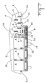
- Figure 1 shows part of a relay box 1 having a carrier plate 2.
- the relay box 1 serves to connect electrical conductors to a relay 4.
- the relay box 1 houses a carrier for the relay signal conductors and control conductors which are to be switched.
- a relay box housing has the carrier plate 2 positioned on an upper side and connected to a side wall 3. Further side walls and housing parts of the relay box are not explicitly illustrated.
- the carrier plate 2 has plug openings 6, 7, 8 for receiving plug contacts of a relay 4. In each of the plug openings 6, 7, 8 there is arranged an electrical receptacle contact 59 which is in turn connected to electrical conductors.
- each relay 4 has four contact pins 58 ( Figure 11). Three of these contact pins 58 are plugged into the plug openings 6, 7, 8 and hence into the associated receptacle contacts. Three plug openings 6, 7, 8 are arranged on the carrier plate 2 to receive three respective contact pins 58 of the relay 4. While the fourth plug opening 9 is located in a plug-in module 5 for receiving a fourth contact pin 58 of the relay 4.
- the plug-in module 5 is detachably mounted to the relay box 1.
- the three plug openings 6, 7, 8 are arranged near the side wall 3.
- the side wall 3 has a mount 12 in the form of a first and a second retaining member 14, 15.
- the first and second retaining members 14, 15 are each constructed in the form of an elongate angled holding strip.
- the first and the second retaining members 14, 15 are angled with respect to each other and project from the side wall 3 at a predetermined spacing, so that two opposing holding edges 48 are formed.
- the retaining member 15 has a latching cutout 49 for receiving a latching lug on the plug-in module 5.
- the side wall 3 has a cutout 11 which is arranged parallel to and between the first and second retaining members 14, 15. Both the cutout 11 and the first and second retaining members 14, 15 are freely accessible from the upper side, so that a plug-in module 5 can be pushed into either the cutout 11 or the mount 12.
- a relay 4 has all four contact pins 58 ( Figure 11) on an underside and, when a relay 4 is plugged in, these are arranged in the direction of the carrier plate 2. However, at least one contact pin 58 is arranged next to the carrier plate 2 and is plugged into a fourth plug opening 9 in a plug-in module 5.
- the plug-in module 5 has a rear side which is secured in the mount 12.
- a fuse mount 50 which serves to hold a fuse 16.
- the fuse mount 50 is freely accessible from above the fourth plug opening 9 located between the fuse mount 50 and the rear side of the plug-in module 5.
- the fourth plug opening 9 is preferably arranged with the longitudinal side parallel to the rear side of the plug-in module 5.
- the fuse mount 50 is preferably arranged on the upper side, parallel to the side edge of the rear side of the plug-in module 5. Because of the preferred arrangement of the fuse mount 50 and the fourth plug opening 9, a compact structure of the plug-in module 5 is possible with a small surface area on the upper side.
- the arrangement of the fuse mount 50 on the upper side of the plug-in module 5 offers the advantage that it is easily discernible which fuse 16 belongs with which relay 4.
- a conductor 10 is connected to the plug-in module 5.
- the longitudinal side of the fourth plug opening 9 is not arranged parallel to the longitudinal sides of the first, second and third plug openings 6, 7, 8, to prevent incorrect insertion of the relay 4.
- the contact pins associated with the plug openings 6, 7, 8, 9 are also arranged in the corresponding orientation.
- the second and third plug openings 7, 8 are used to connect control conductors to the relay 4.
- the first plug opening 6 and the fourth plug opening 9 are used as terminals for a signal conductor to be switched.
- the relay 4 serves as a switch which closes or opens the conductor to be switched (completes or opens the circuit) by way of the first and fourth plug openings 6, 9, in dependence on the control signals.
- Figure 2 shows a view from above of the carrier plate 2.
- a first and a second retaining member 21, 22 of the fuse mount 50 are arranged opposite one another at a predetermined spacing.
- the retaining members 21, 22 have on the mutually facing sides latching hooks which hold a fuse 16 firmly after it has been pushed into the fuse mount 50 from above.
- a fifth and a sixth plug opening 19, 20 which are arranged with their longitudinal sides corresponding to the longitudinal side of the fuse mount 50.
- the fifth and sixth plug openings 19, 20 serve to receive a first and a second fuse contact 17, 18 of a fuse 16.
- a fuse 16 is pushed from above, with the first and second fuse contacts 17, 18 forward, into the fuse mount 50 and the correspondingly associated fifth and sixth plug openings 19, 20. In so doing, the fuse 16 is pushed in far enough for the fuse 16 to be held firmly in a seated position by the first and second retaining members 21, 22.
- the relays 4 have two diametrically arranged spacers 51 on two opposing side faces.
- the arrangement of the spacers 51 is selected to ensure correct insertion of the relay 4 into the plug openings of the carrier plate 2 and into the plug opening of the plug-in module 5.
- a plug opening arrangement 52 used for plugging in a single relay 4 is encircled by a dashed line.
- a corresponding plug opening arrangement 52 is provided, with the plug opening arrangements 52 being arranged next to one another near an edge of the carrier plate 2.
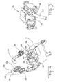
- FIG. 3 shows a perspective view of the rear side of the plug-in module 5.
- the shape of the first and second retaining members 21, 22 can clearly be seen.
- Each retaining member 21, 22 has at the upper end a latching hook 56 for receiving a fuse 16.
- the two retaining members 21, 22 are surrounded by a protective frame 23.
- the protective frame 23 has raised protective elements 54 in the region of the first and second retaining members 21, 22 which are extended beyond the retaining members 21, 22. Between the retaining members 21, 22, the protective frame 23 has connection web 53.
- the preferred embodiment of the protective frame 23 makes it possible to mount and remove the fuse 16 simply and yet ensures that the retaining members 21, 22 are screened, so that inadvertently detaching the fuse 16 or damaging the retaining members 21, 22 is prevented.
- Two mutually parallel rails 25 are constructed on the rear side of the plug-in module 5 near the fourth plug opening 9.
- the rails 25 run substantially parallel to a longitudinal axis of the plug-in module 5.
- the rails 25 serve to guide and orient the plug-in module 5 in the cutout 11. The position of the rails 25 when a plug-in module 5 is pushed in can clearly be seen in Figure 2.
- the plug-in module 5 has first and a second rails 26, 27 located on the side edges of the rear side facing opposite one another.
- the first and second rails 26, 27 are pushed into the region delimited by the first and second angled retaining members 14, 15.
- the lateral spacing between the first and second holding rails 26, 27 are matched to the spacing between the first and second retaining members 14, 15.
- the first and second holding rails 26, 27 have a stop wall 30 which lies on the upper side of the first and second retaining members 14. The position of the stop wall 30 establishes the vertical position of a plug-in module 5 when plugged into the carrier plate 2.
- a latching lug 24 which latches into the latching cutout 49 (Figure 1) is constructed in the top right-hand region of the rear side of the plug-in module 5.
- the plug-in module 5 is detached by urging a flexible tab 55 on which the latching lug 24 is formed away from the latching cutout 49.
- the flexible tab 55 is connected to the housing of the plug-in module 5 by connection webs 57.
- Figure 4 shows a view of the underside of the plug-in module 5, with a first and a second holding cutout 28, 29 formed by the first and second holding rails 26, 27 being clearly visible.
- a cable opening 38 for receiving a plug connector 37 is provided on the underside of the plug-in module 5.
- An electrical conductor 10 is connected to the plug connector 37.
- a first and a second clamp opening 31, 32 are provided on the underside for receiving a bridge clamp 33.
- the bridge clamp 33 has a first and a second clamping arm 34, 36, being electrically connected to one another by a rear connection plate 35.
- the first and second clamp limbs 34, 36 and the connection plate 35 are made from an electrically conductive material.
- the housing of the plug-in module 5 and the relay box 1 are made from an electrically insulating material.
- the first and second clamp limbs 34, 36 each have two opposing double clamps.
- a latching lug 39 projects from a short transverse side of the connection plate 35. When the bridge clamp 33 is pushed into the first and second clamp openings 31, 32, the latching lug 39 engages in a latching cutout 40 on the inside of the housing. In this way, the bridge clamp 33 is securing latched.
- Corresponding fixing means are also constructed on the plug connector 37 and the inner wall of the cable opening 38 in order to connect the plug connector 37 firmly to the plug-in module 5.
- Figure 5 shows the plug-in module 5 with the bridge clamp 33 plugged in and the plugged-in plug connector 37 with the electrical conductor 10.
- FIG 6 shows the upper side of the plug-in module 5 in an enlarged illustration.
- the first clamping arm34 of the bridge clamp 33 is illustrated diagrammatically in the fourth plug opening 9.
- a contact pin of the relay 4, which is plugged into the fourth plug opening 9, is received by the first clamping arm 34 to form an electrical connection.
- the second clamping arm36 can be seen diagrammatically in the sixth plug opening 20. If a fuse with a second fuse contact 18 is pushed into the fuse mount 50, then the second fuse contact 18 is grasped by the second clamping arm 36 to form an electrical contact between the bridge clamp 33 and the second fuse contact 18.
- the plug connector 37 can be seen in the fifth plug opening 19. When a fuse 16 is plugged in, the plug connector 37 receives the first fuse contact 17 and makes an electrical connection between the conductor 10 and the first fuse contact 17.
- the electrical contact is clearly shown between the electrical conductor 10, with a conductor 46, and a first contact 44.
- the first contact 44 is arranged in the plug connector 37. Above the first contact 44 in the housing of the plug-in module 5, the fifth plug opening 19 is illustrated.
- the first contact 44 comprises two contact arms which are pre-tensioned toward each other and form a funnel-like receiving region corresponding with the fifth plug opening 19.
- first and second contact arms 34, 36 of the bridge clamp 33 can clearly be seen.
- the first contact arm 34 is associated with the fourth plug opening 9 and the second contact arm 36 is associated with the fifth plug opening 20.
- the conductor 10 to be switched is connected through the fifth plug opening 19, the fuse 16, the sixth plug opening 20, the bridge clamp 33 and the fourth plug opening 9 to a contact pin of the relay 4.
- the relay 4 preferably has as the input to the conductor to be switched by a plug contact which is associated with the second plug opening 7.
- the first and third plug openings 6, 8 are used to feed control signals and preferably a control voltage to the relay.
- Figure 11 shows a relay 4 from the underside, with four contact pins 58 which project downwards out of the relay 4.
- An advantage of the invention consists in setting at least one electrical terminal of a relay outside a carrier plate.
- the missing electrical terminal is constructed on a plug-in module 5 which is detachably connected to the carrier plate 2.
Landscapes
- Physics & Mathematics (AREA)
- Electromagnetism (AREA)
- Details Of Connecting Devices For Male And Female Coupling (AREA)
- Connector Housings Or Holding Contact Members (AREA)
Applications Claiming Priority (2)
| Application Number | Priority Date | Filing Date | Title |
|---|---|---|---|
| DE10107213 | 2001-02-16 | ||
| DE10107213 | 2001-02-16 |
Publications (2)
| Publication Number | Publication Date |
|---|---|
| EP1233437A2 true EP1233437A2 (fr) | 2002-08-21 |
| EP1233437A3 EP1233437A3 (fr) | 2002-11-06 |
Family
ID=7674246
Family Applications (1)
| Application Number | Title | Priority Date | Filing Date |
|---|---|---|---|
| EP02002666A Withdrawn EP1233437A3 (fr) | 2001-02-16 | 2002-02-06 | Module enfichable, plaque de support et agencement de relais |
Country Status (3)
| Country | Link |
|---|---|
| US (1) | US6709299B2 (fr) |
| EP (1) | EP1233437A3 (fr) |
| BR (1) | BR0200391A (fr) |
Cited By (1)
| Publication number | Priority date | Publication date | Assignee | Title |
|---|---|---|---|---|
| US7741572B2 (en) | 2004-01-19 | 2010-06-22 | Abb Oy | Switching device module |
Families Citing this family (13)
| Publication number | Priority date | Publication date | Assignee | Title |
|---|---|---|---|---|
| WO2002082608A1 (fr) * | 2001-04-06 | 2002-10-17 | Yazaki Corporation | Boite de jonction electrique |
| US7583883B2 (en) * | 2005-07-26 | 2009-09-01 | Adc Telecommunications, Inc. | Fiber optic connector holder |
| US9237685B2 (en) | 2006-08-18 | 2016-01-12 | Delphi Technologies, Inc. | Lightweight audio system for automotive applications and method |
| US7733659B2 (en) | 2006-08-18 | 2010-06-08 | Delphi Technologies, Inc. | Lightweight audio system for automotive applications and method |
| US8149582B2 (en) * | 2008-10-29 | 2012-04-03 | Ecolab Inc. | Detachable module system |
| WO2010099415A1 (fr) | 2009-02-27 | 2010-09-02 | Delphi Technologies, Inc. | Système audio léger pour applications automobiles et procédé |
| US9322405B2 (en) * | 2013-10-29 | 2016-04-26 | Emerson Climate Technologies, Inc. | Rotary compressor with vapor injection system |
| US9480177B2 (en) | 2012-07-27 | 2016-10-25 | Emerson Climate Technologies, Inc. | Compressor protection module |
| DE112014001287B4 (de) * | 2013-03-14 | 2023-04-20 | Yazaki Corporation | Elektronische Baugruppenstruktur und elektrischer Verteilerkasten |
| JP6138560B2 (ja) * | 2013-04-15 | 2017-05-31 | 矢崎総業株式会社 | 電子部品の組付構造及び電気接続箱 |
| EP3384603B1 (fr) * | 2016-12-12 | 2019-04-10 | MRS Corporate, Inc. | Composant de traitement électronique enfichable modulaire et système de traitement réparti formé à partir de ce dernier |
| CN108990343B (zh) * | 2018-08-20 | 2024-04-09 | 畅充科技(北京)有限公司 | 电器盒 |
| DE202020100373U1 (de) * | 2020-01-24 | 2021-04-27 | WAGO Verwaltungsgesellschaft mit beschränkter Haftung | Set aus einem Leiteranschlusselement und einem Befestigungselement |
Family Cites Families (8)
| Publication number | Priority date | Publication date | Assignee | Title |
|---|---|---|---|---|
| DE3334097C1 (de) * | 1983-09-21 | 1985-04-04 | Bayerische Motoren Werke AG, 8000 München | Zentraler Stromverteiler fuer die Verdrahtung von Kraftfahrzeugen |
| US5038050A (en) * | 1989-10-31 | 1991-08-06 | Yazaki Eds | Junction relay box |
| US5179503A (en) * | 1991-04-19 | 1993-01-12 | United Technologies Automotive, Inc. | Modular automobile power distribution box |
| US5295870A (en) * | 1992-12-11 | 1994-03-22 | Electro-Wire Products, Inc. | Modular electrical assembly and removable wedge therefor |
| FR2742004B1 (fr) * | 1995-12-05 | 1998-01-02 | Sylea | Boite de connexion |
| JPH1083849A (ja) * | 1996-09-11 | 1998-03-31 | Sumitomo Wiring Syst Ltd | 配電ボックス |
| DE19745857A1 (de) * | 1996-10-17 | 1998-04-23 | Whitaker Corp | Sicherungsleiste |
| JP3410951B2 (ja) * | 1998-02-20 | 2003-05-26 | 矢崎総業株式会社 | 電気接続箱 |
-
2002
- 2002-02-06 EP EP02002666A patent/EP1233437A3/fr not_active Withdrawn
- 2002-02-14 US US10/075,723 patent/US6709299B2/en not_active Expired - Fee Related
- 2002-02-15 BR BR0200391-0A patent/BR0200391A/pt not_active IP Right Cessation
Cited By (1)
| Publication number | Priority date | Publication date | Assignee | Title |
|---|---|---|---|---|
| US7741572B2 (en) | 2004-01-19 | 2010-06-22 | Abb Oy | Switching device module |
Also Published As
| Publication number | Publication date |
|---|---|
| BR0200391A (pt) | 2002-10-08 |
| US6709299B2 (en) | 2004-03-23 |
| US20020142670A1 (en) | 2002-10-03 |
| EP1233437A3 (fr) | 2002-11-06 |
Similar Documents
| Publication | Publication Date | Title |
|---|---|---|
| US6709299B2 (en) | Plug-in module, carrier plate and relay arrangement | |
| JP4118347B2 (ja) | 電力の横断方向分配部材を有する分配盤 | |
| EP1501133B1 (fr) | Boîte de raccordement pour le raccordement à un panneau solaire | |
| US6203328B1 (en) | Connector for engaging end region of circuit substrate | |
| EP0313239A1 (fr) | Panneau de jacks à insertion frontale des modules à jack avec des assemblages de lampes | |
| JP2006505915A (ja) | ネットワーク接続センサ組立体 | |
| PL168076B1 (pl) | Blok polaczenia na przelacznicy dla instalacji telekomunikacyjnych PL PL PL PL PL PL | |
| US3931601A (en) | Receptacle device ground fault circuit interrupter | |
| JPH0373505B2 (fr) | ||
| KR970000125B1 (ko) | 배선 장치용 접속기 보유기 | |
| US6816044B2 (en) | Electrical switching element | |
| JP4046781B2 (ja) | 電力を横方向に分配する分配器軌条 | |
| US5779498A (en) | Flat cable connector | |
| EP0079805B1 (fr) | Boîtier d'un équipement de télécommunication | |
| JP3751352B2 (ja) | インターフェース装置 | |
| US4874317A (en) | Jackfield with front terminals | |
| RU2391752C2 (ru) | Соединитель и устройство с врезными контактами для телекоммуникационной и информационной техники | |
| US7044803B2 (en) | High density patching system with longframe jacks | |
| CA2490604C (fr) | Structure de connexion entre base de barre omnibus et carte de circuit imprime | |
| US20160248180A1 (en) | Electronic device | |
| EP0313240A1 (fr) | Module à jack avec des assemblages de lampes | |
| KR102135070B1 (ko) | 접촉기 | |
| US4813880A (en) | Arrangement for main distribution frames | |
| PL202360B1 (pl) | Szyna zbiorcza uziomowa i wtyk ochronny dla łączówki złącznej lub rozłącznej w technologii telekomunikacyjnej i przesyłania danych | |
| CN118099872A (zh) | 电源轨道及轨道插座 |
Legal Events
| Date | Code | Title | Description |
|---|---|---|---|
| PUAI | Public reference made under article 153(3) epc to a published international application that has entered the european phase |
Free format text: ORIGINAL CODE: 0009012 |
|
| AK | Designated contracting states |
Kind code of ref document: A2 Designated state(s): AT BE CH CY DE DK ES FI FR GB GR IE IT LI LU MC NL PT SE TR |
|
| AX | Request for extension of the european patent |
Free format text: AL;LT;LV;MK;RO;SI |
|
| PUAL | Search report despatched |
Free format text: ORIGINAL CODE: 0009013 |
|
| AK | Designated contracting states |
Kind code of ref document: A3 Designated state(s): AT BE CH CY DE DK ES FI FR GB GR IE IT LI LU MC NL PT SE TR |
|
| AX | Request for extension of the european patent |
Free format text: AL;LT;LV;MK;RO;SI |
|
| 17P | Request for examination filed |
Effective date: 20021130 |
|
| AKX | Designation fees paid |
Designated state(s): DE ES FR GB IT SE |
|
| 17Q | First examination report despatched |
Effective date: 20090804 |
|
| STAA | Information on the status of an ep patent application or granted ep patent |
Free format text: STATUS: THE APPLICATION IS DEEMED TO BE WITHDRAWN |
|
| 18D | Application deemed to be withdrawn |
Effective date: 20091215 |