EP1233648A2 - Transducteur électroacoustique - Google Patents
Transducteur électroacoustique Download PDFInfo
- Publication number
- EP1233648A2 EP1233648A2 EP01890336A EP01890336A EP1233648A2 EP 1233648 A2 EP1233648 A2 EP 1233648A2 EP 01890336 A EP01890336 A EP 01890336A EP 01890336 A EP01890336 A EP 01890336A EP 1233648 A2 EP1233648 A2 EP 1233648A2
- Authority
- EP
- European Patent Office
- Prior art keywords
- electrode
- membrane
- microphone
- capsule
- electrostatic
- Prior art date
- Legal status (The legal status is an assumption and is not a legal conclusion. Google has not performed a legal analysis and makes no representation as to the accuracy of the status listed.)
- Granted
Links
Images
Classifications
-
- H—ELECTRICITY
- H04—ELECTRIC COMMUNICATION TECHNIQUE
- H04R—LOUDSPEAKERS, MICROPHONES, GRAMOPHONE PICK-UPS OR LIKE ACOUSTIC ELECTROMECHANICAL TRANSDUCERS; ELECTRIC HEARING AIDS; PUBLIC ADDRESS SYSTEMS
- H04R19/00—Electrostatic transducers
- H04R19/04—Microphones
Definitions
- the invention relates to electroacoustic transducers that operate as sound pickups Find application in microphone capsule and work on an electrostatic basis. Such Regardless of their physical mode of operation, transducers have a membrane, which is exposed to the sound field and directly excited to vibrate by it becomes.
- the object of the invention is thus an electrostatic microphone.
- the electrodes of the electrostatic transducers are an elastic, tensioned membrane and one rigid electrode, which is usually only called the electrode. They both form a capacitor whose capacity changes due to pressure fluctuations in the sound field. Between an electrical field is built up in the electrodes of the electrostatic converter, it is possible the capacity changes of the converter with the help of a downstream amplifier convert into electrical voltage changes.
- both have listed Types of electrostatic sound recorders have one major disadvantage: they are against humidity sensitive. There, electrically seen, the capacitor described above high impedance, it is absolutely necessary for a successful electroacoustic conversion, that the first stage of the downstream amplifier is also designed with high impedance is. It is obvious that increased humidity in high-resistance electrical devices poses a great risk to their reliability. a 100% protection of the amplifier against negative influences of the air humidity is through to achieve consistent application of the known stripping measures. there is successfully prevented by sealing with different types of varnish that the air humidity can adversely affect the electrical properties of the amplifier. at the capsule is much more complicated to protect against moisture.
- the only direct one The insulating distance between the electrodes of the capacitor is the spacer ring.
- An increased Air humidity causes precipitation that is negative in the area of the spacer ring affects the quality of the isolation path and affects the operation of the microphone makes unpleasant pattering noise noticeable.
- the aim of the invention is to provide better protection than hitherto against the risk of a short circuit between the electrodes of a microphone of the type mentioned at high Secure moisture in the environment without reducing the size of the microphone capsule or the manufacturing costs for them increase significantly.
- these goals are achieved in that on the rigid electrode, preferably on the side facing away from the membrane, at least one electrical resistance arranged, preferably glued, with the during operation of the microphone is connected to a voltage source.
- the rigid electrode and thus its edge area and so the sensitive area of the membrane holder by a few fractions of a degree above the ambient temperature warms up, which is enough to reliably prevent condensation. Since a cavity is always provided at the back of the electrode, which consists of The dimensions of the. Are absolutely necessary for acoustic adjustment Capsule not changed.
- the power supply is not a problem and can be done through its own lines, yes hardly any power has to be transmitted and which can therefore be made thin, respectively.
- microphones that work on an electrostatic basis require a voltage source for the power supply of the amplifier downstream of the capsule, which in turn either from its own battery supply device or from a so-called phantom power (mixer) is provided. This phantom power too can be used to operate the resistor.
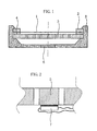
- Fig. 1 shows a conventional electrostatic converter in section.
- a membrane 1 is inserted into the capsule carrier 3 with the aid of a membrane ring 2.
- the spacer ring 4 holds the membrane 1 and the electrode 5 at a small distance of about 40 microns or less from each other and is made of an electrically good insulating material, preferably a film, made.
- the invention can be seen from FIG. 2. Part of the electrode 5 is greatly enlarged shown. An electrical resistor 7 is attached to the electrode and is connected to a voltage source connected. Its function is to heat the electrode 5. To the To achieve or prevent precipitation of water vapor in a targeted manner Water vapor "contaminated" environment necessary and sufficient, a small Temperature difference of just a few tenths of a degree Celsius between two areas or components to accomplish.
- the microphone capsule Since the microphone capsule is built into a microphone housing, and it with a mesh basket Protected from mechanical damage, it is easy to find such a temperature difference between the inside of the capsule and the microphone housing or the mesh cap to reach. This prevents condensation in the capsule and the Capsule is reliably protected against the moisture in the air.
- a preferred variant of the invention provides an electrical control circuit, which allows a predefined temperature difference even when the outside temperatures are very different between the inside of the capsule and the microphone housing upright receive or create.
- a control loop is in the knowledge of the invention for the Expert easy to design.
- an electrical resistance with known temperature sensitivity can be arranged outside the capsule.
- the size this resistance and the size of the heating resistor on the electrode are in Operation periodically or continuously compared.
- the current through the heating resistor is changed until the desired temperature difference is reached. So on the one hand the capsule from overheating protected, on the other hand minimizes power consumption and also protects against moisture guaranteed over a wide range of ambient temperature.
- any ohmic resistance can be used as the heating resistor 7, preferably are especially with the last-mentioned variant of the invention with resistors known temperature coefficient used.
- As an adhesive all come in the Electrical engineering usual adhesives in question, knowing the composition of the used electrode 5 and the resistor 7, the expert can easily choose to meet.
Landscapes
- Physics & Mathematics (AREA)
- Engineering & Computer Science (AREA)
- Acoustics & Sound (AREA)
- Signal Processing (AREA)
- Electrostatic, Electromagnetic, Magneto- Strictive, And Variable-Resistance Transducers (AREA)
- Transducers For Ultrasonic Waves (AREA)
- Audible-Bandwidth Dynamoelectric Transducers Other Than Pickups (AREA)
- Piezo-Electric Transducers For Audible Bands (AREA)
- Electrophonic Musical Instruments (AREA)
- Glass Compositions (AREA)
- Control Of Electric Motors In General (AREA)
Priority Applications (1)
| Application Number | Priority Date | Filing Date | Title |
|---|---|---|---|
| AT01890336T ATE413786T1 (de) | 2001-02-14 | 2001-12-12 | Elektroakustischer wandler |
Applications Claiming Priority (2)
| Application Number | Priority Date | Filing Date | Title |
|---|---|---|---|
| AT0022701A AT413922B (de) | 2001-02-14 | 2001-02-14 | Elektroakustischer wandler |
| AT2272001 | 2001-02-14 |
Publications (3)
| Publication Number | Publication Date |
|---|---|
| EP1233648A2 true EP1233648A2 (fr) | 2002-08-21 |
| EP1233648A3 EP1233648A3 (fr) | 2006-09-20 |
| EP1233648B1 EP1233648B1 (fr) | 2008-11-05 |
Family
ID=3669899
Family Applications (1)
| Application Number | Title | Priority Date | Filing Date |
|---|---|---|---|
| EP01890336A Expired - Lifetime EP1233648B1 (fr) | 2001-02-14 | 2001-12-12 | Transducteur électroacoustique |
Country Status (6)
| Country | Link |
|---|---|
| US (1) | US6792123B2 (fr) |
| EP (1) | EP1233648B1 (fr) |
| JP (1) | JP4038051B2 (fr) |
| CN (1) | CN1248543C (fr) |
| AT (2) | AT413922B (fr) |
| DE (1) | DE50114468D1 (fr) |
Families Citing this family (6)
| Publication number | Priority date | Publication date | Assignee | Title |
|---|---|---|---|---|
| AT410498B (de) * | 2001-02-20 | 2003-05-26 | Akg Acoustics Gmbh | Elektroakustische kapsel |
| JP2005244427A (ja) * | 2004-02-25 | 2005-09-08 | Audio Technica Corp | 単一指向性コンデンサマイクロホンユニット |
| JP4802985B2 (ja) * | 2006-11-07 | 2011-10-26 | ヤマハ株式会社 | スピーカ |
| US9716934B2 (en) * | 2015-04-24 | 2017-07-25 | Apple Inc. | Liquid ingress-redirecting acoustic device reservoir |
| CN113132854B (zh) * | 2019-12-30 | 2025-01-28 | 楼氏电子(苏州)有限公司 | 微机电系统换能器和麦克风组件 |
| US11638079B1 (en) | 2020-07-31 | 2023-04-25 | Waymo Llc | External microphone heater |
Family Cites Families (4)
| Publication number | Priority date | Publication date | Assignee | Title |
|---|---|---|---|---|
| US2115129A (en) * | 1935-06-08 | 1938-04-26 | Telefunken Gmbh | Loudspeaker |
| NL7313455A (nl) * | 1973-10-01 | 1975-04-03 | Philips Nv | Mikrofoon met elektrostatische capsule. |
| US4450929A (en) * | 1980-05-09 | 1984-05-29 | Marrs Ralph E | Acoustic energy systems |
| JP3371045B2 (ja) * | 1994-12-26 | 2003-01-27 | 株式会社オーディオテクニカ | コンデンサマイクロホン |
-
2001
- 2001-02-14 AT AT0022701A patent/AT413922B/de not_active IP Right Cessation
- 2001-12-12 DE DE50114468T patent/DE50114468D1/de not_active Expired - Lifetime
- 2001-12-12 EP EP01890336A patent/EP1233648B1/fr not_active Expired - Lifetime
- 2001-12-12 AT AT01890336T patent/ATE413786T1/de active
-
2002
- 2002-01-29 CN CNB021032157A patent/CN1248543C/zh not_active Expired - Fee Related
- 2002-02-01 JP JP2002025473A patent/JP4038051B2/ja not_active Expired - Fee Related
- 2002-02-08 US US10/071,038 patent/US6792123B2/en not_active Expired - Fee Related
Also Published As
| Publication number | Publication date |
|---|---|
| JP2002271899A (ja) | 2002-09-20 |
| CN1248543C (zh) | 2006-03-29 |
| EP1233648A3 (fr) | 2006-09-20 |
| JP4038051B2 (ja) | 2008-01-23 |
| ATA2272001A (de) | 2005-10-15 |
| US20020110254A1 (en) | 2002-08-15 |
| ATE413786T1 (de) | 2008-11-15 |
| EP1233648B1 (fr) | 2008-11-05 |
| DE50114468D1 (de) | 2008-12-18 |
| AT413922B (de) | 2006-07-15 |
| US6792123B2 (en) | 2004-09-14 |
| CN1371234A (zh) | 2002-09-25 |
Similar Documents
| Publication | Publication Date | Title |
|---|---|---|
| DE2913772C3 (de) | Halbleiter-Druckwandler | |
| DE69215599T2 (de) | Biegsame piezoelektrische Vorrichtung | |
| DE2221062C3 (de) | Kapazitiver Druckwandler | |
| DE2411212A1 (de) | Druckmesseinrichtung | |
| DE2758666A1 (de) | Elektroakustischer wandler | |
| DE1416447A1 (de) | Frequenzselektiver Verstaerker | |
| EP1233648A2 (fr) | Transducteur électroacoustique | |
| AT505967A2 (de) | Implantierbarer akustischer sensor | |
| WO2015064216A1 (fr) | Capteur piézoélectrique | |
| DE102018202347A1 (de) | Mikrofonsystem mit einem hohen akustischem überlastpunkt | |
| JP3449599B2 (ja) | 積層チップ型バリスタ | |
| EP2091269A2 (fr) | Appareil auditif résistant à l'eau | |
| DE2939397C2 (fr) | ||
| CN110199400B (zh) | 电子滤波器电路 | |
| DE3519576A1 (de) | Sensor | |
| DE2022652A1 (de) | Auf mechanische Beanspruchung ansprechender Halbleiterwandler | |
| DE69022111T2 (de) | Verfahren zur Herstellung eines variablen Kondensator- mikrophons. | |
| DE202013012023U1 (de) | Aktormodul mit einem in einem Gehäuse angeordneten Vielschichtaktor und konstant extrem niedrigen Leckstrom an der Aktoroberfläche | |
| DE102009013336A1 (de) | Pyroelektrisches Material, Strahlungssensor, Verfahren zur Herstellung eines Strahlungssensors und Verwendung von Lithiumtantalat und Lithiumniobat | |
| WO2005115052A1 (fr) | Microphone a condensateur | |
| DE3419256C2 (de) | Elektroakustische Wandlereinrichtung | |
| DE2141643C3 (de) | Erregerschaltung für einen piezoelektrischen Kristall | |
| DE2330800C3 (de) | Elektroakustischer Wandler nach dem elektrostatischen Prinzip und Verfahren zu dessen Herstellung | |
| DE3413921A1 (de) | Verfahren zur herstellung eines infrarotdetektors | |
| EP1727162A3 (fr) | Composant électronique et methode pour sa fabrication |
Legal Events
| Date | Code | Title | Description |
|---|---|---|---|
| PUAI | Public reference made under article 153(3) epc to a published international application that has entered the european phase |
Free format text: ORIGINAL CODE: 0009012 |
|
| AK | Designated contracting states |
Kind code of ref document: A2 Designated state(s): AT BE CH CY DE DK ES FI FR GB GR IE IT LI LU MC NL PT SE TR |
|
| AX | Request for extension of the european patent |
Free format text: AL;LT;LV;MK;RO;SI |
|
| PUAL | Search report despatched |
Free format text: ORIGINAL CODE: 0009013 |
|
| AK | Designated contracting states |
Kind code of ref document: A3 Designated state(s): AT BE CH CY DE DK ES FI FR GB GR IE IT LI LU MC NL PT SE TR |
|
| AX | Request for extension of the european patent |
Extension state: AL LT LV MK RO SI |
|
| 17P | Request for examination filed |
Effective date: 20070320 |
|
| AKX | Designation fees paid |
Designated state(s): AT DE FR GB IT |
|
| 17Q | First examination report despatched |
Effective date: 20070425 |
|
| GRAP | Despatch of communication of intention to grant a patent |
Free format text: ORIGINAL CODE: EPIDOSNIGR1 |
|
| GRAS | Grant fee paid |
Free format text: ORIGINAL CODE: EPIDOSNIGR3 |
|
| GRAA | (expected) grant |
Free format text: ORIGINAL CODE: 0009210 |
|
| AK | Designated contracting states |
Kind code of ref document: B1 Designated state(s): AT DE FR GB IT |
|
| REG | Reference to a national code |
Ref country code: GB Ref legal event code: FG4D Free format text: NOT ENGLISH |
|
| REF | Corresponds to: |
Ref document number: 50114468 Country of ref document: DE Date of ref document: 20081218 Kind code of ref document: P |
|
| PLBE | No opposition filed within time limit |
Free format text: ORIGINAL CODE: 0009261 |
|
| STAA | Information on the status of an ep patent application or granted ep patent |
Free format text: STATUS: NO OPPOSITION FILED WITHIN TIME LIMIT |
|
| 26N | No opposition filed |
Effective date: 20090806 |
|
| PGFP | Annual fee paid to national office [announced via postgrant information from national office to epo] |
Ref country code: AT Payment date: 20101119 Year of fee payment: 10 |
|
| PGFP | Annual fee paid to national office [announced via postgrant information from national office to epo] |
Ref country code: IT Payment date: 20101223 Year of fee payment: 10 Ref country code: GB Payment date: 20101229 Year of fee payment: 10 |
|
| PGFP | Annual fee paid to national office [announced via postgrant information from national office to epo] |
Ref country code: FR Payment date: 20120104 Year of fee payment: 11 |
|
| PGFP | Annual fee paid to national office [announced via postgrant information from national office to epo] |
Ref country code: DE Payment date: 20111229 Year of fee payment: 11 |
|
| REG | Reference to a national code |
Ref country code: AT Ref legal event code: MM01 Ref document number: 413786 Country of ref document: AT Kind code of ref document: T Effective date: 20121212 |
|
| GBPC | Gb: european patent ceased through non-payment of renewal fee |
Effective date: 20121212 |
|
| REG | Reference to a national code |
Ref country code: FR Ref legal event code: ST Effective date: 20130830 |
|
| REG | Reference to a national code |
Ref country code: DE Ref legal event code: R119 Ref document number: 50114468 Country of ref document: DE Effective date: 20130702 |
|
| PG25 | Lapsed in a contracting state [announced via postgrant information from national office to epo] |
Ref country code: AT Free format text: LAPSE BECAUSE OF NON-PAYMENT OF DUE FEES Effective date: 20121212 Ref country code: DE Free format text: LAPSE BECAUSE OF NON-PAYMENT OF DUE FEES Effective date: 20130702 |
|
| PG25 | Lapsed in a contracting state [announced via postgrant information from national office to epo] |
Ref country code: FR Free format text: LAPSE BECAUSE OF NON-PAYMENT OF DUE FEES Effective date: 20130102 Ref country code: GB Free format text: LAPSE BECAUSE OF NON-PAYMENT OF DUE FEES Effective date: 20121212 |
|
| PG25 | Lapsed in a contracting state [announced via postgrant information from national office to epo] |
Ref country code: IT Free format text: LAPSE BECAUSE OF NON-PAYMENT OF DUE FEES Effective date: 20121212 |