EP1233649B1 - Commande thermosensible pour un réceptacle chauffant pour liquides - Google Patents
Commande thermosensible pour un réceptacle chauffant pour liquides Download PDFInfo
- Publication number
- EP1233649B1 EP1233649B1 EP02251091A EP02251091A EP1233649B1 EP 1233649 B1 EP1233649 B1 EP 1233649B1 EP 02251091 A EP02251091 A EP 02251091A EP 02251091 A EP02251091 A EP 02251091A EP 1233649 B1 EP1233649 B1 EP 1233649B1
- Authority
- EP
- European Patent Office
- Prior art keywords
- vessel
- actuator
- base
- liquid
- liquid heating
- Prior art date
- Legal status (The legal status is an assumption and is not a legal conclusion. Google has not performed a legal analysis and makes no representation as to the accuracy of the status listed.)
- Expired - Lifetime
Links
Images



Classifications
-
- H—ELECTRICITY
- H05—ELECTRIC TECHNIQUES NOT OTHERWISE PROVIDED FOR
- H05B—ELECTRIC HEATING; ELECTRIC LIGHT SOURCES NOT OTHERWISE PROVIDED FOR; CIRCUIT ARRANGEMENTS FOR ELECTRIC LIGHT SOURCES, IN GENERAL
- H05B1/00—Details of electric heating devices
- H05B1/02—Automatic switching arrangements specially adapted to apparatus ; Control of heating devices
- H05B1/0202—Switches
- H05B1/0213—Switches using bimetallic elements
-
- A—HUMAN NECESSITIES
- A47—FURNITURE; DOMESTIC ARTICLES OR APPLIANCES; COFFEE MILLS; SPICE MILLS; SUCTION CLEANERS IN GENERAL
- A47J—KITCHEN EQUIPMENT; COFFEE MILLS; SPICE MILLS; APPARATUS FOR MAKING BEVERAGES
- A47J27/00—Cooking-vessels
- A47J27/21—Water-boiling vessels, e.g. kettles
- A47J27/21008—Water-boiling vessels, e.g. kettles electrically heated
- A47J27/21041—Water-boiling vessels, e.g. kettles electrically heated with heating elements arranged outside the water vessel
-
- A—HUMAN NECESSITIES
- A47—FURNITURE; DOMESTIC ARTICLES OR APPLIANCES; COFFEE MILLS; SPICE MILLS; SUCTION CLEANERS IN GENERAL
- A47J—KITCHEN EQUIPMENT; COFFEE MILLS; SPICE MILLS; APPARATUS FOR MAKING BEVERAGES
- A47J27/00—Cooking-vessels
- A47J27/21—Water-boiling vessels, e.g. kettles
- A47J27/21008—Water-boiling vessels, e.g. kettles electrically heated
- A47J27/2105—Water-boiling vessels, e.g. kettles electrically heated of the cordless type, i.e. whereby the water vessel can be plugged into an electrically-powered base element
-
- A—HUMAN NECESSITIES
- A47—FURNITURE; DOMESTIC ARTICLES OR APPLIANCES; COFFEE MILLS; SPICE MILLS; SUCTION CLEANERS IN GENERAL
- A47J—KITCHEN EQUIPMENT; COFFEE MILLS; SPICE MILLS; APPARATUS FOR MAKING BEVERAGES
- A47J27/00—Cooking-vessels
- A47J27/21—Water-boiling vessels, e.g. kettles
- A47J27/21008—Water-boiling vessels, e.g. kettles electrically heated
- A47J27/21058—Control devices to avoid overheating, i.e. "dry" boiling, or to detect boiling of the water
- A47J27/21083—Control devices to avoid overheating, i.e. "dry" boiling, or to detect boiling of the water with variable operating parameters, e.g. temperature or boiling period
-
- A—HUMAN NECESSITIES
- A47—FURNITURE; DOMESTIC ARTICLES OR APPLIANCES; COFFEE MILLS; SPICE MILLS; SUCTION CLEANERS IN GENERAL
- A47J—KITCHEN EQUIPMENT; COFFEE MILLS; SPICE MILLS; APPARATUS FOR MAKING BEVERAGES
- A47J27/00—Cooking-vessels
- A47J27/21—Water-boiling vessels, e.g. kettles
- A47J27/21008—Water-boiling vessels, e.g. kettles electrically heated
- A47J27/21058—Control devices to avoid overheating, i.e. "dry" boiling, or to detect boiling of the water
- A47J27/21108—Control devices to avoid overheating, i.e. "dry" boiling, or to detect boiling of the water using a bimetallic element
- A47J27/21125—Control devices to avoid overheating, i.e. "dry" boiling, or to detect boiling of the water using a bimetallic element the bimetallic element being a snapping disc
-
- G—PHYSICS
- G05—CONTROLLING; REGULATING
- G05D—SYSTEMS FOR CONTROLLING OR REGULATING NON-ELECTRIC VARIABLES
- G05D23/00—Control of temperature
- G05D23/19—Control of temperature characterised by the use of electric means
- G05D23/1902—Control of temperature characterised by the use of electric means characterised by the use of a variable reference value
-
- G—PHYSICS
- G05—CONTROLLING; REGULATING
- G05D—SYSTEMS FOR CONTROLLING OR REGULATING NON-ELECTRIC VARIABLES
- G05D23/00—Control of temperature
- G05D23/19—Control of temperature characterised by the use of electric means
- G05D23/275—Control of temperature characterised by the use of electric means with sensing element expanding, contracting, or fusing in response to changes of temperature
- G05D23/27535—Details of the sensing element
- G05D23/2754—Details of the sensing element using bimetallic element
-
- H—ELECTRICITY
- H01—ELECTRIC ELEMENTS
- H01H—ELECTRIC SWITCHES; RELAYS; SELECTORS; EMERGENCY PROTECTIVE DEVICES
- H01H37/00—Thermally-actuated switches
- H01H37/02—Details
- H01H37/12—Means for adjustment of "on" or "off" operating temperature
- H01H37/18—Means for adjustment of "on" or "off" operating temperature by varying bias on the thermal element due to a separate spring
-
- H—ELECTRICITY
- H01—ELECTRIC ELEMENTS
- H01H—ELECTRIC SWITCHES; RELAYS; SELECTORS; EMERGENCY PROTECTIVE DEVICES
- H01H37/00—Thermally-actuated switches
- H01H37/002—Thermally-actuated switches combined with protective means
-
- H—ELECTRICITY
- H01—ELECTRIC ELEMENTS
- H01H—ELECTRIC SWITCHES; RELAYS; SELECTORS; EMERGENCY PROTECTIVE DEVICES
- H01H37/00—Thermally-actuated switches
- H01H37/02—Details
- H01H37/32—Thermally-sensitive members
- H01H37/52—Thermally-sensitive members actuated due to deflection of bimetallic element
- H01H37/54—Thermally-sensitive members actuated due to deflection of bimetallic element wherein the bimetallic element is inherently snap acting
- H01H37/5409—Bistable switches; Resetting means
Definitions
- the present invention relates to liquid heating vessels and to heating bases having a region for receiving a thermally sensitive actuator of a thermally sensitive control.
- the controls comprise two thermally sensitive actuators, arranged, in use, in good thermal contact with the base of the vessel. More specifically, the actuators are snap action bimetallic actuators. In contrast to a creep action actuator, which will curve gradually as its temperature increases, a snap-action actuator is pre-stressed during its manufacture so that it will reverse its curvature suddenly upon reaching a predetermined temperature.
- the control is operable to disconnect the power supply to the vessel heater in the event of the vessel heater overheating. This situation might arise for example if the vessel boils dry or if it is switched on with no liquid in it.
- the control may also comprise a steam sensitive actuator to disconnect the power supply to the vessel heater in the event of liquid in the vessel boiling, or a separate boiling switch may be provided.
- liquid heating vessels having controls as above are limited to heating liquid to a single temperature, i.e. boiling. In certain circumstances, however, it is desirable to be able to heat the liquid to a temperature below its boiling point.
- Various techniques have been proposed to achieve this objective.
- This arrangement has a number of disadvantages. Firstly it is limited to controls incorporating a trip lever, since it is the movement of the trip lever which acts to disconnect the power supply to the heater once the selected temperature is reached. Heating can subsequently only be resumed on intervention of the user to manually reset the trip lever. The arrangement is therefore unable to automatically maintain the liquid in the vessel at or around a desired temperature. The arrangement also requires significant modification of the control and additional components, adding to the manufacturing costs.
- one of the snap-acting bimetallic overheat protection actuators provided in the aforementioned control can be adapted to operate at a predetermined lower temperature, thereby obviating the need for a separate, lower temperature actuator.
- the operating temperature of the actuator i.e. the temperature at which reversal of curvature occurs, may be varied on application of a biasing force to the actuator.
- a snap acting bimetallic actuator designed to reverse curvature at a certain temperature may therefore be controlled to operate at a range of different temperatures on application of a mechanical force to its blade.
- Heating bases for a liquid heating vessel are also disclosed in WO-A-01/64084 published 07.09.2001, WO-A-99/54903, WO-A-99/48331, GB-A-2 308 743, WO-A-95/34188, WO-A-99/48333 and GB-A-2 322 274.
- the present invention provides a heating base in or for use in a liquid heating vessel as described in claim 1.
- a control may be provided comprising first and second snap action bimetallic actuators arranged so as in use to make good thermal contact with the base of the vessel; and biasing means arranged to exert a variable force on the second actuator so as to vary its operating temperature in use.
- the temperature of liquid in the vessel may be controlled by varying the biasing force exerted on the second actuator in use, a suitable mechanism being coupled to the second actuator to interrupt or reduce the power supply to the heater upon operation of the second actuator.
- the first actuator will be chosen so as to have an operating temperature such that it will operate only in the event of an overheat condition.
- the second actuator will not only act to operate at a lower temperature, indicative of liquid in the vessel attaining a desired temperature in normal use, but will also be able to act as an overheat protection actuator in a dry boil or dry switch on situation.
- the temperature of the vessel base will be indicative of the temperature of liquid in the vessel, a relationship which can be determined empirically.
- the relationship between the biasing force and the operating temperature of the actuator may also then be established empirically. The correlation between a given biasing force and the liquid temperature at which operation of the actuator will occur may thus be determined.
- the biasing means may be configured so as to apply the biasing force to the actuator in the same direction as that in which the actuator deflects on heating. In this case, an increased biasing force will reduce the operating temperature of the actuator.
- the biasing means is configured to apply the biasing force to the snap action bimetallic actuator in a direction opposite to its deflection, such that a higher operating temperature results upon application of the load.
- the actuator is chosen to have a nominal operating temperature in an unbiased condition which will allow the base of the vessel to be heated to a temperature corresponding to the lowest desired liquid temperature.
- the biasing means may exert force on the actuator indirectly, for example through movement of the entire control relative to the base of the vessel, but in the preferred arrangement, the biasing means acts directly on a part of the actuator.
- the biasing means may cooperate with any suitable part of the actuator, e.g. a peripheral part thereof.
- the biasing means comprises a spring, and the biasing force is varied by compression or expansion of the spring.
- the spring may take any suitable configuration e.g. a coil or a leaf spring, but in a particularly preferred embodiment, the spring is a formed as a torsion spring.
- the biasing spring is suitably coupled to a control member for varying the force applied by the spring.
- the control member comprises a cam surface which cooperates with the spring.
- the cam may be a sliding cam, a particularly beneficial and simple arrangement is obtained if a rotary cam is used. More specifically, in the preferred embodiment using a torsion spring as mentioned above, one limb of the spring may be arranged to cooperate with the actuator, and the other limb to cooperate with the rotary cam surface.
- the cam and the spring may be preassembled for mounting together onto the control.
- the cam surface may have a plurality of discrete levels, which would result in a vessel capable of heating liquid to a plurality of discrete predetermined temperatures. However, it is preferred that the cam surface is continuously variable, thus providing a continuous range of operating temperatures for the control.
- the cam surface is operatively coupled to a spindle provided, in use, with a knob for manipulation by a user.
- the appliance is preferably marked with a suitable scale to link the position of the knob to the corresponding liquid temperature.
- the control may also include resetting means, whereby the control member may be moved to apply a relatively high force to the spring and hence the actuator, causing the actuator to recover its original curvature.
- This resetting could be done by permitting the cam to rotate to a position at which it exerts a sufficiently high force on the actuator, or by configuring and arranging the control member so as to permit sliding in an axial direction, whereby resetting may be achieved merely by pressing the control member
- a control may operate to disconnect the power to the vessel heater once the liquid in the vessel has reached a predetermined temperature, whereafter the power can only be reconnected by manually resetting the control.
- Such an arrangement would be achieved by the actuator acting to trip a trip lever, as used in Applicant's U18 or U28 controls.
- a boiling sensitive actuator may also act on the trip lever, again as is the case in the Applicant's U18 or U28 controls.
- control could cycle power to the heater and maintain the liquid in the vessel at or around the desired temperature. This could be achieved by the actuator simply operating with a leaf spring mounted contact, as used in Applicant's U17 or U27 controls.
- a separate steam switch e.g. Applicant's R48 switch may be employed to disconnect the power when liquid in the vessel boils.
- the heater may comprise a sheathed heating element suitably secured to the base of the vessel.
- the element is preferably mounted, e.g. soldered or brazed, to a heat diffusion member which is mounted to the non-liquid contacting side of the vessel base, and the actuators arranged in good thermal contact with the heat diffusion member.
- the heat diffusion member is preferably provided with heat flow management means which reduces the flow of heat from the heater into the mounting location for that actuator.
- Such means may comprise one or more grooves or slots provided around selected portions of the mounting location. These grooves or slots may take any appropriate form e.g. they may be linear or curved, e.g. arcuate or parabolic. In the preferred embodiment, a plurality of circularly arcuate slots is provided around the mounting location.
- the heater of the heating vessel may equally be a thick film heater suitably arranged in the base of the vessel.
- the track layout of the heater may be configured so as at least partially to isolate the variable temperature actuator from the direct heating effect of the heating element and improve the sensitivity of the actuator in response to the liquid temperature within the vessel. This could be achieved for example by placing the actuator in contact with a portion of the heater where there are no, or relatively few, heating tracks, by selecting the track widths in that region appropriately (by making the tracks wider the local heating effect will be lower) or by effectively shorting out sections of track by over- or under-printing with a more highly conductive material such as silver. This will reduce the amount of heat generated in that region, whereby the actuator will be more sensitive to the temperature of liquid in the vessel.
- the invention also provides a liquid heating vessel having a thick film heater provided on its base, and a thermally sensitive control, said control comprising a first bimetallic actuator arranged so as in use to make a good thermal contact with a region of the base of the vessel for sensing a temperature indicative of the temperature of liquid being heated in the vessel, said region having a relatively low heating effect; and a second overheat protection bimetallic actuator arranged in good thermal contact with a portion of the heater having a relatively high heating effect.
- the invention also extends to a heater adapted for use in such a liquid heating vessel.
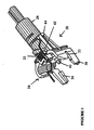
- FIG. 1 shows a control embodying the present invention.
- the control is based on the Applicant's U18 control but with certain components modified in accordance with the invention.
- control 2 comprises a body moulding 4 which mounts various electrical components of the control (not shown), a spring loaded trip lever 6 which is mounted to the body moulding 4, and a plate 8 which is mounted to the body moulding 4 and carries two snap action bimetallic actuators 10, 12.
- the bimetallic actuators are of the type described in GB 1542242.
- the bimetallic actuators 10, 12 are mounted in good thermal contact with the base of a liquid heating vessel, and when either actuator reaches its operating temperature, indicative of an overheat condition, it reverses its curvature with a snap action to open a set of electrical contacts in the control and trip the trip lever 6 which maintains the contacts open until the control is reset by a user.
- the biasing means comprises a torsion spring 22, a support block 24 and a control member 26, which components are preassembled into a sub-assembly 28 which is clipped onto one of the arc shields 30 of the control moulding 4.
- the support block 24 is provided with a groove 32 which locates over a rib 34 provided on the control moulding 4 and is also provided with locating arms 36, 38 which engage with the sides of the arc shield 30, and a clip 40 for engaging over an edge of the arc shield 30 to hold the sub-assembly 28 in position.
- the support block 24 includes a cylindrical spigot 42 for mounting the torsion spring 22.
- the spring 22 is retained on the spigot by a pillar 44 provided on the block 24 which engages one leg of the spring 22.
- the support block 24 also includes a contoured spigot 46 for mounting the control member 26.
- the spigot 46 includes a longitudinal rib 48 which extends axially along the surface of the spigot 46 adjacent to a slot 50 provided in the enlarged end portion 52 of the spigot 46.
- the tubular control member 26 is push fitted over the end portion 52 of the spigot 46, the slot 50 allowing the passage of a lug (not shown) provided on an internal wall of the control member 26.
- the lug cooperates with the rib 48 to act as an end-stop, preventing rotation of the control member 26 through more than 360°.
- the enlarged end portion 52 acts to retain the control member on the spigot 46.
- the spigot 46 is also provided with a larger diameter base portion 54 which receives the inner wall of the control member 26.
- the control member 26 is provided with a non-stepped, axially facing, cam surface 56 which extends around substantially the whole of the control member 26 as shown in Fig. 3.
- the cam surface 56 is provided on a helical flight 58 extending around the control member 26.
- the cam surface 56 engages one limb of the torsion spring 22.
- the spring 22 is made of metal or an suitably other temperature resistant material and as described above is mounted on the spigot 42 of the control block moulding 24.
- the spring 22 comprises a coiled body 60 with respective end limbs 62, 64. As shown schematically in Figure 4, one limb 62 of the spring 22, locates against the cam surface 56, while the other limb 64 is positioned against a portion 70 of the bimetallic actuator 12.
- the end of the limb 64 engages the peripheral portion 70 of the actuator 12 generally opposite the tongue 72 by which the actuator is mounted to the plate 8(not shown) of the control.
- the push rod which would normally transmit the movement of the actuator to the trip lever 6 of the control has also been modified from that in the standard U18 control.
- the push rod is a separate ceramic rod which is located in a locating bore 74, in this construction the rod is formed as an integral part 76 of the trip lever 6, located approximately opposite the standard position.
- the complete control is then mounted to the base of or for a liquid heating vessel.
- a base 8 is shown in Figure 5.
- a heat diffuser plate 80 of e.g. aluminium is mounted to the base of the vessel in a conventional manner eg by welding or brazing.
- the control is mounted to mounting bosses 82 provided on the diffuser plate 80.
- the actuator 12 engages a region 84 of the diffuser plate 80 which is surrounded on three sides by three spaced slots 86, 88, 90.
- These slots act to isolate the region 84 to some extent from the sheathed heater 92 provided around the edge of the diffuser plate 80 so that the temperature of the region 84 reflects more accurately the temperature of the base of the vessel and thus the temperature of the liquid being heated inside the vessel. No such slots are provided on the opposite side of the diffuser plate 80 in the region where the overheat protection actuator 10 locates.
- control member 26 If it is desired to heat liquid to a predetermined temperature, the control member 26 is rotated clockwise from its rest position by its knob (not shown) to a desired rotational position corresponding to the desired temperature (anti-clockwise movement of the control member is prevented by engagement of the rib 44 with the internal lug provided on the axial wall of the control member 26).
- the torsion spring 60 As the control member 26 rotates the torsion spring 60 is stressed by the engagement of the limb 62 with the cam surface 56. As the rotation proceeds, a greater force is applied to the torsion spring 60, which in turn increases the biasing force acting on the peripheral portion of actuator 12 via the spring limb 64. Due to this increasing force, the temperature which the blade must attain in order to reverse its curvature is increased.
- the operating temperature of the actuator increases, meaning that liquid being heated in the vessel will be heated to a higher temperature before operation of the actuator 12.
- the control member 26 will be held in its desired angular position by friction.
- the operating temperature of the actuator can be set to above 100°C, whereby the vessel acts to boil liquid.
- the actuator 12 When the actuator 12 operates, it operates on the push rod 76 provided on the trip lever 6 to open a set of electrical contacts in the electrical supply to the vessel heater thereby disconnecting the power supply to the heater.
- the tripping of the trip lever 6 also acts to maintain the contacts open, even after resetting of the actuator, thereby preventing re-heating of the liquid until the trip lever is reset manually by a user.
- the actuator 12 will reset when its temperature falls below a predetermined value. This may be accelerated by applying a high force against the actuator 12. This could, for example be achieved by rotating the control member to its "boil” position, or, in a modification of the arrangement shown, moving the control member axially to load the spring.
- the invention is suitable for liquid heating vessels which use either sheathed heating elements or thick film elements attached to or forming at least a part of the base of the vessel.
- control may be modified to allow resetting of the actuator 12 by allowing the control member 26 to move axially on the spigot 46, so that pushing the member 26 will reset the actuator.
Landscapes
- Engineering & Computer Science (AREA)
- Food Science & Technology (AREA)
- Physics & Mathematics (AREA)
- General Physics & Mathematics (AREA)
- Automation & Control Theory (AREA)
- Cookers (AREA)
- Control Of Resistance Heating (AREA)
- Investigating Or Analyzing Materials By The Use Of Fluid Adsorption Or Reactions (AREA)
- Control Of Temperature (AREA)
- Instantaneous Water Boilers, Portable Hot-Water Supply Apparatuses, And Control Of Portable Hot-Water Supply Apparatuses (AREA)
- Thermally Insulated Containers For Foods (AREA)
- Frying-Pans Or Fryers (AREA)
Claims (25)
- Base chauffante (8) dans ou pour un récipient pour chauffer un liquide, laquelle base comprend une unité de chauffage (92) et une région (84) pour recevoir un actionneur thermo-sensible (12) d'une commande thermo-sensible (2) servant à détecter une température indiquant la température du liquide que l'on chauffe dans le récipient, caractérisée en ce que ladite base (8) comporte des moyens de gestion du flux de chaleur (86, 88, 90) qui diminuent le flux de chaleur provenant de l'unité de chauffage (92) dans ladite région (84) de la base (8).
- Base chauffante telle que revendiquée dans la revendication 1, dans laquelle ladite unité de chauffage (92) consiste en un élément chauffant protégé monté sur un élément de diffusion de chaleur (80) situé sur ladite base (8).
- Base chauffante telle que revendiquée dans la revendication 2, dans laquelle lesdits moyens de gestion du flux de chaleur sont disposés dans ledit élément de diffusion de chaleur (80).
- Base chauffante telle que revendiquée dans la revendication 3, dans laquelle lesdits moyens de gestion du flux de chaleur comprennent une ou plusieurs rainures ou fentes (86, 88, 90) disposées autour de parties sélectionnées de l'emplacement de montage.
- Base chauffante telle que revendiquée dans la revendication 4, dans laquelle lesdites rainures ou fentes (86, 88, 90) sont de forme arquée.
- Base chauffante telle que revendiquée dans la revendication 5, dans laquelle lesdites rainures ou fentes (86, 88, 90) définissent une région de montage circulaire (84).
- Base chauffante telle que revendiquée dans l'une quelconque des revendications 2 à 6, dans laquelle ledit élément chauffant (92) est disposé autour de la périphérie dudit élément de diffusion de chaleur (80), tandis que lesdits moyens de gestion de flux de chaleur (86, 88, 90) se situent entre l'élément de chauffage (92) et la région (84).
- Base chauffante telle que revendiquée dans la revendication 1, dans laquelle ladite unité de chauffage est un film de chauffage épais.
- Récipient pour chauffer un liquide comprenant une base chauffante telle que revendiquée dans l'une quelconque des revendications précédentes, et une commande thermo-sensible (2) comportant un actionneur thermo-sensible (12) servant à détecter une température indiquant la température du liquide que l'on chauffe dans le récipient, lequel actionneur (12) se trouve en bon contact thermique avec ladite région (84) de ladite base (8).
- Récipient pour chauffer un liquide tel que revendiqué dans la revendication 9, dans lequel ledit actionneur (12) consisté en un actionneur bimétallique à action brusque.
- Récipient pour chauffer un liquide tel que revendiqué dans la revendication 9 ou 10, dans lequel ladite commande (2) comprend un premier et un second actionneurs bimétalliques à action brusque (10, 12) disposés de manière à avoir un bon contact thermique avec la base du récipient, ainsi qu'un moyen de poussée (20) conçu pour appliquer une force variable sur le second actionneur (12) de manière à faire varier sa température de fonctionnement lors de l'utilisation, lequel second actionneur (12) est monté de manière à avoir un bon contact thermique avec ladite région (84) de ladite base (8).
- Récipient pour chauffer un liquide tel que revendiqué dans la revendication 11, dans lequel le moyen de poussée (20) est conçu pour appliquer la force de poussée au dit second actionneur (12) dans une direction opposée à celle de son écartement de sorte qu'une température de fonctionnement plus élevée se traduit par l'application d'une plus grande force de poussée.
- Récipient pour chauffer un liquide tel que revendiqué dans la revendication 11 ou 12, dans lequel le moyen de poussée applique une force directement sur une partie du second actionneur (12).
- Récipient pour chauffer un liquide tel que revendiqué dans la revendication 11, 12 ou 13, dans lequel le moyen de poussée comprend un ressort (22).
- Récipient pour chauffer un liquide tel que revendiqué dans la revendication 14, dans lequel le ressort (22) consiste en un ressort hélicoïdal, à lame ou de torsion.
- Récipient pour chauffer un liquide tel que revendiqué dans la revendication 14 ou 15, dans lequel le ressort de poussée (22) est couplé à un élément de commande (26) pour faire varier la force appliquée par le ressort (22) au second actionneur (12).
- Récipient pour chauffer un liquide tel que revendiqué dans la revendication 16, dans lequel l'élément de commande (26) comprend une surface de came (56) qui coopère avec le ressort (22).
- Récipient pour chauffer un liquide tel que revendiqué dans la revendication 17, dans lequel la surface de came (56) est une surface de came rotative.
- Récipient pour chauffer un liquide tel que revendiqué dans la revendication 17 ou 18, dans lequel ledit ressort comprend un ressort de torsion (22) possédant deux membres qui s'étendent depuis ses extrémités, un membre (64) du ressort entrant en interaction avec l'actionneur (12) et l'autre membre (62) coopérant avec la surface de came (56).
- Récipient pour chauffer un liquide tel que revendiqué dans l'une quelconque des revendications 17 à 19, dans lequel la surface de came (56) comprend plusieurs niveaux discrets.
- Récipient pour chauffer un liquide tel que revendiqué dans l'une quelconque des revendications 17 à 19, dans lequel la surface de came (56) varie de façon continue.
- Récipient pour chauffer un liquide tel que revendiqué dans l'une quelconque des revendications 16 à 21, dans lequel l'élément de commande (26) est couplé opérationnellement à une broche qui, à son tour, comporte un bouton en vue de la manipulation par l'utilisateur.
- Récipient pour chauffer un liquide tel que revendiqué dans l'une quelconque des revendications 11 à 22, comprenant en outre un moyen, tel qu'un levier de déclenchement (6), permettant de réinitialiser le second actionneur (12) après son fonctionnement.
- Récipient pour chauffer un liquide tel que revendiqué dans la revendication 23 considérée dépendante de l'une quelconque des revendications 16 à 22, dans lequel l'élément de commande (26) est configuré et disposé de manière à coulisser dans le sens axial pour effectuer la réinitialisation.
- Récipient pour chauffer un liquide tel que revendiqué dans l'une quelconque des revendications 9 à 24, comprenant en outre un moyen sensible à l'ébullition permettant de déconnecter l'alimentation électrique de l'unité de chauffage du récipient lorsque le liquide dans le récipient bout.
Priority Applications (1)
| Application Number | Priority Date | Filing Date | Title |
|---|---|---|---|
| EP05005665A EP1565037B1 (fr) | 2001-02-19 | 2002-02-18 | Commande thermosensible pour un réceptacle chauffant pour liquides |
Applications Claiming Priority (2)
| Application Number | Priority Date | Filing Date | Title |
|---|---|---|---|
| GB0104062 | 2001-02-19 | ||
| GB0104062A GB2372421B (en) | 2001-02-19 | 2001-02-19 | Thermally sensitive controls |
Related Child Applications (1)
| Application Number | Title | Priority Date | Filing Date |
|---|---|---|---|
| EP05005665A Division EP1565037B1 (fr) | 2001-02-19 | 2002-02-18 | Commande thermosensible pour un réceptacle chauffant pour liquides |
Publications (2)
| Publication Number | Publication Date |
|---|---|
| EP1233649A1 EP1233649A1 (fr) | 2002-08-21 |
| EP1233649B1 true EP1233649B1 (fr) | 2005-08-17 |
Family
ID=9909043
Family Applications (2)
| Application Number | Title | Priority Date | Filing Date |
|---|---|---|---|
| EP05005665A Expired - Lifetime EP1565037B1 (fr) | 2001-02-19 | 2002-02-18 | Commande thermosensible pour un réceptacle chauffant pour liquides |
| EP02251091A Expired - Lifetime EP1233649B1 (fr) | 2001-02-19 | 2002-02-18 | Commande thermosensible pour un réceptacle chauffant pour liquides |
Family Applications Before (1)
| Application Number | Title | Priority Date | Filing Date |
|---|---|---|---|
| EP05005665A Expired - Lifetime EP1565037B1 (fr) | 2001-02-19 | 2002-02-18 | Commande thermosensible pour un réceptacle chauffant pour liquides |
Country Status (5)
| Country | Link |
|---|---|
| EP (2) | EP1565037B1 (fr) |
| CN (2) | CN100504704C (fr) |
| AT (2) | ATE417486T1 (fr) |
| DE (2) | DE60230336D1 (fr) |
| GB (1) | GB2372421B (fr) |
Cited By (1)
| Publication number | Priority date | Publication date | Assignee | Title |
|---|---|---|---|---|
| US11306945B2 (en) | 2018-09-07 | 2022-04-19 | Bleckmann Gmbh & Co. Kg | Heating system for heating a fluid medium |
Families Citing this family (17)
| Publication number | Priority date | Publication date | Assignee | Title |
|---|---|---|---|---|
| GB0103658D0 (en) * | 2001-02-14 | 2001-03-28 | Strix Ltd | Electric beverage maker |
| GB0316037D0 (en) * | 2003-07-08 | 2003-08-13 | Otter Controls Ltd | Improvements relating to thermal control units |
| GB0423433D0 (en) * | 2004-10-21 | 2004-11-24 | Strix Ltd | Temperature control in liquid heating vessels |
| DE102005018597B3 (de) | 2005-04-21 | 2006-11-09 | Bleckmann Gmbh & Co. Kg | Heizsystem mit Temperatursicherungseinrichtungen und Wärmeübertragungselement hierfür |
| GB0518338D0 (en) | 2005-09-09 | 2005-10-19 | Strix Ltd | Heaters for liquid heating vessels |
| GB0519593D0 (en) * | 2005-09-26 | 2005-11-02 | Strix Ltd | Liquid heating vessels |
| GB0707083D0 (en) | 2007-04-12 | 2007-05-23 | Strix Ltd | Improvements in liquid heating vessels |
| US7783176B2 (en) | 2007-06-28 | 2010-08-24 | Strix Limited | Heaters for liquid heating vessels |
| US8097834B2 (en) | 2007-06-28 | 2012-01-17 | Strix Limited | Liquid heating vessels |
| CN101354981B (zh) * | 2008-04-17 | 2012-03-28 | 柯赐龙 | 一种温控器中的热敏致动结构 |
| DE102008030930B4 (de) | 2008-07-02 | 2010-08-26 | Eichenauer Heizelemente Gmbh & Co. Kg | Heizboden mit Temperaturelementbefestigung |
| CN101630165B (zh) * | 2008-07-19 | 2011-07-20 | 浙江家泰电器制造有限公司 | 液体加热器皿过热保护控制器组件 |
| GB2470053A (en) * | 2009-05-07 | 2010-11-10 | Otter Controls Ltd | Thermal control for liquid heating appliance. |
| GB2497978A (en) * | 2011-12-23 | 2013-07-03 | Otter Controls Ltd | Liquid heating vessel and control |
| CN104181956B (zh) * | 2013-05-23 | 2016-07-06 | 广东新宝电器股份有限公司 | 温度控制装置及应用该装置的液体加热器 |
| EP3001274B1 (fr) * | 2013-05-23 | 2019-07-10 | Guangdong Xinbao Electrical Appliances Holdings Co. Ltd. | Dispositif de régulation de la température et ses applications comme dispositif de chauffage de liquide |
| CN107491140B (zh) * | 2017-09-15 | 2019-01-29 | 浙江家泰电器制造有限公司 | 温度敏感控制器 |
Family Cites Families (18)
| Publication number | Priority date | Publication date | Assignee | Title |
|---|---|---|---|---|
| GB774911A (en) * | 1954-07-08 | 1957-05-15 | Eric Hardman Taylor | Improvements in or relating to snap action electric switches |
| US3573700A (en) * | 1968-11-29 | 1971-04-06 | Therm O Disc Inc | Adjustable thermostat |
| US3676817A (en) * | 1971-02-22 | 1972-07-11 | Therm O Disc Inc | Adjustable thermostat |
| BE818448A (fr) * | 1973-08-04 | 1975-02-03 | Regulateur de temperature combine | |
| US4365228A (en) * | 1981-04-03 | 1982-12-21 | Robertshaw Controls Company | Thermostat construction having a one piece plunger with a wing-like section and method of making the same |
| GB2308743B (en) * | 1994-06-09 | 1998-04-15 | Strix Ltd | Water heating vessels |
| GB9411573D0 (en) * | 1994-06-09 | 1994-08-03 | Strix Ltd | Liquid heating vessels |
| IN192511B (fr) * | 1994-06-09 | 2004-04-24 | Strix Ltd | |
| GB9627104D0 (en) * | 1996-12-31 | 1997-02-19 | Strix Ltd | Liquid heating apparatus |
| GB2322274B (en) * | 1997-02-17 | 1999-01-13 | Strix Ltd | Controls for electric heaters |
| WO1999002080A1 (fr) * | 1997-07-11 | 1999-01-21 | Strix Limited | Receptacles chauffant des liquides et dispositifs de reglage adaptes |
| GB2329523B (en) * | 1997-09-17 | 2001-03-21 | Strix Ltd | Thermally Sensitive Controls |
| AU2944099A (en) * | 1998-03-17 | 1999-10-11 | Strix Limited | Thermally sensitive controls |
| GB9805751D0 (en) * | 1998-03-17 | 1998-05-13 | Strix Ltd | Electric heaters |
| CN1139089C (zh) * | 1998-04-21 | 2004-02-18 | 奥特控制有限公司 | 关于电热元件的控制装置的改进 |
| GB2349508B (en) * | 1999-04-26 | 2003-04-16 | Otter Controls Ltd | Improvements relating to thermally-responsive controls |
| CN100373280C (zh) * | 1999-07-21 | 2008-03-05 | 奥特控制有限公司 | 水加热容器的相关改进 |
| GB2359978B (en) * | 2000-03-02 | 2003-12-24 | Otter Controls Ltd | Liquid heating appliance and "keep warm" control |
-
2001
- 2001-02-19 GB GB0104062A patent/GB2372421B/en not_active Expired - Fee Related
-
2002
- 2002-02-18 DE DE60230336T patent/DE60230336D1/de not_active Expired - Lifetime
- 2002-02-18 DE DE60205515T patent/DE60205515T2/de not_active Expired - Lifetime
- 2002-02-18 AT AT05005665T patent/ATE417486T1/de not_active IP Right Cessation
- 2002-02-18 EP EP05005665A patent/EP1565037B1/fr not_active Expired - Lifetime
- 2002-02-18 AT AT02251091T patent/ATE302539T1/de not_active IP Right Cessation
- 2002-02-18 EP EP02251091A patent/EP1233649B1/fr not_active Expired - Lifetime
- 2002-02-19 CN CNB021084912A patent/CN100504704C/zh not_active Expired - Lifetime
- 2002-02-19 CN CN2009101360906A patent/CN101532729B/zh not_active Expired - Lifetime
Cited By (1)
| Publication number | Priority date | Publication date | Assignee | Title |
|---|---|---|---|---|
| US11306945B2 (en) | 2018-09-07 | 2022-04-19 | Bleckmann Gmbh & Co. Kg | Heating system for heating a fluid medium |
Also Published As
| Publication number | Publication date |
|---|---|
| CN100504704C (zh) | 2009-06-24 |
| CN1388426A (zh) | 2003-01-01 |
| DE60230336D1 (de) | 2009-01-22 |
| ATE302539T1 (de) | 2005-09-15 |
| ATE417486T1 (de) | 2008-12-15 |
| EP1565037B1 (fr) | 2008-12-10 |
| GB2372421A8 (en) | 2005-04-25 |
| EP1233649A1 (fr) | 2002-08-21 |
| GB2372421B (en) | 2005-07-27 |
| DE60205515D1 (de) | 2005-09-22 |
| CN101532729A (zh) | 2009-09-16 |
| EP1565037A1 (fr) | 2005-08-17 |
| DE60205515T2 (de) | 2006-03-30 |
| GB2372421A (en) | 2002-08-21 |
| GB0104062D0 (en) | 2001-04-04 |
| CN101532729B (zh) | 2011-04-13 |
Similar Documents
| Publication | Publication Date | Title |
|---|---|---|
| EP1233649B1 (fr) | Commande thermosensible pour un réceptacle chauffant pour liquides | |
| US6153859A (en) | Liquid heating vessels | |
| EP0994666B1 (fr) | Element chauffant à couche épaisse | |
| EP2275892A1 (fr) | Contrôle de température dans une bouilloire | |
| US5029303A (en) | Switching device | |
| GB2329523A (en) | Thermally sensitive controls | |
| CN102458194A (zh) | 热控制器 | |
| WO1995019129A1 (fr) | Appareil de chauffage de l'eau | |
| WO1995034188A1 (fr) | Recipients pour chauffer un liquide | |
| US4166994A (en) | Thermostat with positive off position | |
| EP0682352B1 (fr) | Régulateur d'énergie | |
| GB2354927A (en) | Water heating element with adjustable resistance track associated with bimetal control | |
| WO2001006334A1 (fr) | Perfectionnements relatifs aux recipients de chauffage d'eau | |
| EP1702249A1 (fr) | Ameliorations concernant des controles thermiques | |
| GB2336986A (en) | Dual power output liquid heating element arrangement | |
| EP1649790B1 (fr) | Régulation de la temperature pour bouilloire | |
| GB2400005A (en) | Locating sheathed heating element relative to mounting base and thermal control | |
| EP0624890B1 (fr) | Régulateurs d'énergie | |
| GB2365303A (en) | Liquid heating vessels and controls therefor | |
| GB2311898A (en) | Liquid boiling vessel | |
| GB2439657A (en) | Improvements relating to thermal controls | |
| EP1941784A1 (fr) | Ameliorations apportees a des organes regulateurs thermiques | |
| GB2431518A (en) | Improvements relating to thermal control units | |
| HK1001197A (en) | Liquid heating vessels |
Legal Events
| Date | Code | Title | Description |
|---|---|---|---|
| PUAI | Public reference made under article 153(3) epc to a published international application that has entered the european phase |
Free format text: ORIGINAL CODE: 0009012 |
|
| AK | Designated contracting states |
Kind code of ref document: A1 Designated state(s): AT BE CH CY DE DK ES FI FR GB GR IE IT LI LU MC NL PT SE TR |
|
| AX | Request for extension of the european patent |
Free format text: AL;LT;LV;MK;RO;SI |
|
| 17P | Request for examination filed |
Effective date: 20021220 |
|
| 17Q | First examination report despatched |
Effective date: 20030212 |
|
| AKX | Designation fees paid |
Designated state(s): AT BE CH CY DE DK ES FI FR GB GR IE IT LI LU MC NL PT SE TR |
|
| GRAP | Despatch of communication of intention to grant a patent |
Free format text: ORIGINAL CODE: EPIDOSNIGR1 |
|
| GRAS | Grant fee paid |
Free format text: ORIGINAL CODE: EPIDOSNIGR3 |
|
| GRAA | (expected) grant |
Free format text: ORIGINAL CODE: 0009210 |
|
| AK | Designated contracting states |
Kind code of ref document: B1 Designated state(s): AT BE CH CY DE DK ES FI FR GB GR IE IT LI LU MC NL PT SE TR |
|
| PG25 | Lapsed in a contracting state [announced via postgrant information from national office to epo] |
Ref country code: LI Free format text: LAPSE BECAUSE OF FAILURE TO SUBMIT A TRANSLATION OF THE DESCRIPTION OR TO PAY THE FEE WITHIN THE PRESCRIBED TIME-LIMIT Effective date: 20050817 Ref country code: FI Free format text: LAPSE BECAUSE OF FAILURE TO SUBMIT A TRANSLATION OF THE DESCRIPTION OR TO PAY THE FEE WITHIN THE PRESCRIBED TIME-LIMIT Effective date: 20050817 Ref country code: CH Free format text: LAPSE BECAUSE OF FAILURE TO SUBMIT A TRANSLATION OF THE DESCRIPTION OR TO PAY THE FEE WITHIN THE PRESCRIBED TIME-LIMIT Effective date: 20050817 Ref country code: TR Free format text: LAPSE BECAUSE OF FAILURE TO SUBMIT A TRANSLATION OF THE DESCRIPTION OR TO PAY THE FEE WITHIN THE PRESCRIBED TIME-LIMIT Effective date: 20050817 Ref country code: AT Free format text: LAPSE BECAUSE OF FAILURE TO SUBMIT A TRANSLATION OF THE DESCRIPTION OR TO PAY THE FEE WITHIN THE PRESCRIBED TIME-LIMIT Effective date: 20050817 Ref country code: BE Free format text: LAPSE BECAUSE OF FAILURE TO SUBMIT A TRANSLATION OF THE DESCRIPTION OR TO PAY THE FEE WITHIN THE PRESCRIBED TIME-LIMIT Effective date: 20050817 |
|
| REG | Reference to a national code |
Ref country code: GB Ref legal event code: FG4D |
|
| REG | Reference to a national code |
Ref country code: CH Ref legal event code: EP |
|
| REG | Reference to a national code |
Ref country code: IE Ref legal event code: FG4D |
|
| REF | Corresponds to: |
Ref document number: 60205515 Country of ref document: DE Date of ref document: 20050922 Kind code of ref document: P |
|
| PG25 | Lapsed in a contracting state [announced via postgrant information from national office to epo] |
Ref country code: SE Free format text: LAPSE BECAUSE OF FAILURE TO SUBMIT A TRANSLATION OF THE DESCRIPTION OR TO PAY THE FEE WITHIN THE PRESCRIBED TIME-LIMIT Effective date: 20051117 Ref country code: DK Free format text: LAPSE BECAUSE OF FAILURE TO SUBMIT A TRANSLATION OF THE DESCRIPTION OR TO PAY THE FEE WITHIN THE PRESCRIBED TIME-LIMIT Effective date: 20051117 Ref country code: GR Free format text: LAPSE BECAUSE OF FAILURE TO SUBMIT A TRANSLATION OF THE DESCRIPTION OR TO PAY THE FEE WITHIN THE PRESCRIBED TIME-LIMIT Effective date: 20051117 |
|
| PG25 | Lapsed in a contracting state [announced via postgrant information from national office to epo] |
Ref country code: ES Free format text: LAPSE BECAUSE OF FAILURE TO SUBMIT A TRANSLATION OF THE DESCRIPTION OR TO PAY THE FEE WITHIN THE PRESCRIBED TIME-LIMIT Effective date: 20051128 |
|
| REG | Reference to a national code |
Ref country code: GB Ref legal event code: 732E |
|
| PG25 | Lapsed in a contracting state [announced via postgrant information from national office to epo] |
Ref country code: PT Free format text: LAPSE BECAUSE OF FAILURE TO SUBMIT A TRANSLATION OF THE DESCRIPTION OR TO PAY THE FEE WITHIN THE PRESCRIBED TIME-LIMIT Effective date: 20060117 |
|
| PG25 | Lapsed in a contracting state [announced via postgrant information from national office to epo] |
Ref country code: IE Free format text: LAPSE BECAUSE OF NON-PAYMENT OF DUE FEES Effective date: 20060220 |
|
| PG25 | Lapsed in a contracting state [announced via postgrant information from national office to epo] |
Ref country code: LU Free format text: LAPSE BECAUSE OF NON-PAYMENT OF DUE FEES Effective date: 20060228 Ref country code: MC Free format text: LAPSE BECAUSE OF NON-PAYMENT OF DUE FEES Effective date: 20060228 |
|
| REG | Reference to a national code |
Ref country code: CH Ref legal event code: PL |
|
| ET | Fr: translation filed | ||
| PLBE | No opposition filed within time limit |
Free format text: ORIGINAL CODE: 0009261 |
|
| STAA | Information on the status of an ep patent application or granted ep patent |
Free format text: STATUS: NO OPPOSITION FILED WITHIN TIME LIMIT |
|
| 26N | No opposition filed |
Effective date: 20060518 |
|
| REG | Reference to a national code |
Ref country code: IE Ref legal event code: MM4A |
|
| PGFP | Annual fee paid to national office [announced via postgrant information from national office to epo] |
Ref country code: IT Payment date: 20080221 Year of fee payment: 7 |
|
| PG25 | Lapsed in a contracting state [announced via postgrant information from national office to epo] |
Ref country code: CY Free format text: LAPSE BECAUSE OF FAILURE TO SUBMIT A TRANSLATION OF THE DESCRIPTION OR TO PAY THE FEE WITHIN THE PRESCRIBED TIME-LIMIT Effective date: 20050817 |
|
| PG25 | Lapsed in a contracting state [announced via postgrant information from national office to epo] |
Ref country code: IT Free format text: LAPSE BECAUSE OF NON-PAYMENT OF DUE FEES Effective date: 20090218 |
|
| REG | Reference to a national code |
Ref country code: FR Ref legal event code: PLFP Year of fee payment: 15 |
|
| REG | Reference to a national code |
Ref country code: FR Ref legal event code: PLFP Year of fee payment: 16 |
|
| REG | Reference to a national code |
Ref country code: GB Ref legal event code: 732E Free format text: REGISTERED BETWEEN 20171005 AND 20171011 |
|
| REG | Reference to a national code |
Ref country code: FR Ref legal event code: PLFP Year of fee payment: 17 |
|
| PGFP | Annual fee paid to national office [announced via postgrant information from national office to epo] |
Ref country code: NL Payment date: 20190218 Year of fee payment: 18 |
|
| PGFP | Annual fee paid to national office [announced via postgrant information from national office to epo] |
Ref country code: FR Payment date: 20190215 Year of fee payment: 18 |
|
| REG | Reference to a national code |
Ref country code: NL Ref legal event code: MM Effective date: 20200301 |
|
| PG25 | Lapsed in a contracting state [announced via postgrant information from national office to epo] |
Ref country code: NL Free format text: LAPSE BECAUSE OF NON-PAYMENT OF DUE FEES Effective date: 20200301 |
|
| PG25 | Lapsed in a contracting state [announced via postgrant information from national office to epo] |
Ref country code: FR Free format text: LAPSE BECAUSE OF NON-PAYMENT OF DUE FEES Effective date: 20200229 |
|
| PGFP | Annual fee paid to national office [announced via postgrant information from national office to epo] |
Ref country code: GB Payment date: 20210218 Year of fee payment: 20 Ref country code: DE Payment date: 20210218 Year of fee payment: 20 |
|
| REG | Reference to a national code |
Ref country code: DE Ref legal event code: R071 Ref document number: 60205515 Country of ref document: DE |
|
| REG | Reference to a national code |
Ref country code: GB Ref legal event code: PE20 Expiry date: 20220217 |
|
| PG25 | Lapsed in a contracting state [announced via postgrant information from national office to epo] |
Ref country code: GB Free format text: LAPSE BECAUSE OF EXPIRATION OF PROTECTION Effective date: 20220217 |