EP1234099B1 - Bohrloch-schwingungserzeuger - Google Patents
Bohrloch-schwingungserzeuger Download PDFInfo
- Publication number
- EP1234099B1 EP1234099B1 EP00989923A EP00989923A EP1234099B1 EP 1234099 B1 EP1234099 B1 EP 1234099B1 EP 00989923 A EP00989923 A EP 00989923A EP 00989923 A EP00989923 A EP 00989923A EP 1234099 B1 EP1234099 B1 EP 1234099B1
- Authority
- EP
- European Patent Office
- Prior art keywords
- anvil
- pulser
- cylinder
- opening
- combustion
- Prior art date
- Legal status (The legal status is an assumption and is not a legal conclusion. Google has not performed a legal analysis and makes no representation as to the accuracy of the status listed.)
- Expired - Lifetime
Links
- 238000002485 combustion reaction Methods 0.000 claims description 40
- 239000012530 fluid Substances 0.000 claims description 28
- 239000007789 gas Substances 0.000 claims description 19
- UFHFLCQGNIYNRP-UHFFFAOYSA-N Hydrogen Chemical compound [H][H] UFHFLCQGNIYNRP-UHFFFAOYSA-N 0.000 claims description 13
- QVGXLLKOCUKJST-UHFFFAOYSA-N atomic oxygen Chemical compound [O] QVGXLLKOCUKJST-UHFFFAOYSA-N 0.000 claims description 13
- 230000015572 biosynthetic process Effects 0.000 claims description 13
- 239000001257 hydrogen Substances 0.000 claims description 13
- 229910052739 hydrogen Inorganic materials 0.000 claims description 13
- 239000000203 mixture Substances 0.000 claims description 13
- 239000001301 oxygen Substances 0.000 claims description 13
- 229910052760 oxygen Inorganic materials 0.000 claims description 13
- 230000006835 compression Effects 0.000 claims description 8
- 238000007906 compression Methods 0.000 claims description 8
- 239000000463 material Substances 0.000 claims description 7
- 239000012528 membrane Substances 0.000 claims description 6
- 229910000831 Steel Inorganic materials 0.000 claims description 2
- 239000010959 steel Substances 0.000 claims description 2
- 239000011148 porous material Substances 0.000 description 7
- 239000002245 particle Substances 0.000 description 5
- 239000004215 Carbon black (E152) Substances 0.000 description 4
- 229930195733 hydrocarbon Natural products 0.000 description 4
- 150000002430 hydrocarbons Chemical class 0.000 description 4
- 239000007787 solid Substances 0.000 description 3
- 239000002360 explosive Substances 0.000 description 2
- 230000001939 inductive effect Effects 0.000 description 2
- 238000004519 manufacturing process Methods 0.000 description 2
- 238000004140 cleaning Methods 0.000 description 1
- 230000003247 decreasing effect Effects 0.000 description 1
- 238000000151 deposition Methods 0.000 description 1
- 230000008021 deposition Effects 0.000 description 1
- 238000010438 heat treatment Methods 0.000 description 1
- 229910052500 inorganic mineral Inorganic materials 0.000 description 1
- 239000011707 mineral Substances 0.000 description 1
- 239000011435 rock Substances 0.000 description 1
Images

Classifications
-
- E—FIXED CONSTRUCTIONS
- E21—EARTH OR ROCK DRILLING; MINING
- E21B—EARTH OR ROCK DRILLING; OBTAINING OIL, GAS, WATER, SOLUBLE OR MELTABLE MATERIALS OR A SLURRY OF MINERALS FROM WELLS
- E21B28/00—Vibration generating arrangements for boreholes or wells, e.g. for stimulating production
-
- E—FIXED CONSTRUCTIONS
- E21—EARTH OR ROCK DRILLING; MINING
- E21B—EARTH OR ROCK DRILLING; OBTAINING OIL, GAS, WATER, SOLUBLE OR MELTABLE MATERIALS OR A SLURRY OF MINERALS FROM WELLS
- E21B43/00—Methods or apparatus for obtaining oil, gas, water, soluble or meltable materials or a slurry of minerals from wells
- E21B43/003—Vibrating earth formations
Definitions
- the present invention relates to a pulser for generating pressure pulses in a wellbore formed in an earth formation.
- Hydrocarbon fluid is generally produced from an earth formation using a wellbore provided with a casing or liner having perforations at the level of the producing formation.
- the hydrocarbon fluid flows through the pores of the earth formation and the perforations into the wellbore.
- a problem frequently encountered during production is that the pores of the formation are naturally clogged by fine solids or diagenetic mineral particles, or become clogged by fines solid particles in the course of hydrocarbon fluid production, thereby decreasing the flow rate and increasing the flow resistance.
- Another frequently encountered problem is that the perforations extending into the earth formation are contaminated by crushed or fused rock particles as a result of the use of shaped explosive charges to create the perforations, or by residual material from such shaped explosive charges. Such particles and residual materials impede the flow rate of hydrocarbon fluid.
- US patent 4,280,557 discloses a sonic apparatus for cleaning the interior of well tubulars wherein acoustic vibrations dislodge dirt and scale depositions from the pipe walls.
- a pulser for use in a wellbore formed in an earth formation to generate pressure pulses in said wellbore, the pulser comprising a housing provided with an internal combustion engine including a cylinder and a piston arranged to perform a combustion stroke upon combustion of a combustible gas mixture in the cylinder, a first spring arranged to induce the piston to perform a compression stroke upon completion of the combustion stroke, the pulser further comprising a hammer connected to the piston, an anvil movable relative to the housing between a fist position and a second position in which the pulser has a different volume than in the first position, the anvil being arranged so that the hammer impacts against the anvil during the combustion stroke and induces the anvil to move from the first to the second position, and a second spring biasing the anvil from the second to the first position thereof.
- the anvil By the impact of the hammer against the anvil during each combustion stroke, the anvil rapidly moves to the second position and thereby creates a pressure pulse in the fluid present in the wellbore by virtue of the sudden change of volume of the pulser. In this manner a sequence of pressure pulses is generated, which pulses travel into the pores of the earth formation and thereby prevent settling of fine solid particles in the pores.
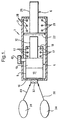
- a pulser 1 for use in a wellbore (not shown) formed in an earth formation (not shown).
- the pulser 1 includes a housing 2 provided with an internal combustion engine 4 and an anvil 6 having a common longitudinal axis coinciding with, or parallel to, the longitudinal axis of the wellbore.
- the engine 4 comprises a cylinder 8 and a piston 10 extending into the cylinder 8 and being movable relative to the cylinder 8 in longitudinal direction thereof.
- a hammer 12 connected to the piston 10 extends in longitudinal direction to the anvil 6.
- the cylinder 8 is at the end thereof opposite the hammer 12 closed by an end wall 14, thereby defining a combustion chamber 16 formed in the cylinder 8 between the piston 10 and the end wall 14.
- the combustion chamber 16 is provided with a glow plug (not shown) connected to a battery (not shown) for temporarily heating the glow plug.
- the anvil 6 includes an anvil plate 22 arranged within the housing and an anvil shaft 25 fixedly connected to the anvil plate 22, the anvil shaft 25 extending through an opening 26 provided in the housing 2 in a manner allowing the anvil 6 to move in longitudinal direction relative to the housing 2 between a retracted position in which the pulser 1 has a first volume and an extended position in which the pulser 1 has a second volume larger than the first volume.
- a spring 28 biases the anvil 6 to the retracted position thereof.
- the relative arrangement of the anvil 6 and the engine 4 is such that the anvil plate 22 is located a short distance from the hammer 12 when both the engine 4 and the anvil 6 are in their respective retracted positions.
- the inlet valve 32 is in fluid communication with an oxygen reservoir 34 via a conduit 36 and with a hydrogen reservoir 38 via a conduit 40.
- the oxygen reservoir 34 contains a supply of oxygen at a selected pressure
- the hydrogen reservoir 38 contains a supply of hydrogen at a selected pressure.
- the inlet valve 32 includes a valve body 42 provided with a disc shaped chamber 44 having a valve seat surface 46 provided with a first opening 48 in fluid communication with the conduit 36, a second opening 50 in fluid communication with the conduit 40, and a third opening 52 in fluid communication with an inlet opening (not shown) provided in the wall of the cylinder 8 via a conduit 54.
- a membrane 56 divides the disc shaped chamber 44 in a first zone 60 in fluid communication with the respective openings 48, 50, 52 and a second zone 62 in fluid communication with the combustion chamber 16 via a conduit 64.
- the membrane 56 is flexible so as to allow the membrane to lay against the valve seat surface 46 if a fluid pressure in zone 62 exceeds a fluid pressure in zone 60.
- Fig. 3 is an exhaust 42 of the engine 4, which exhaust includes an outlet opening 70 formed in the wall of the cylinder 8.
- the piston 10 is shown together with the direction of movement 71 of the piston 10 during a combustion stroke thereof.
- the position of the outlet opening 70 is such that the piston covers the outlet opening 70 during an initial stage of the combustion stroke, and uncovers the outlet opening 70 during a final stage of the combustion stroke.
- the outlet opening 70 is in fluid communication with an expansion chamber 72 provided with a non-return valve 74 allowing combusted gas to flow from the expansion chamber 72 via the non-return valve 74 to the exterior of the engine 4 and preventing inflow of fluid from exterior the engine 4 into the expansion chamber 72.
- the non-return valve 74 includes a passage 76 for combusted gas, which passage 76 is provided with a body of permeable material 78 including sintered steel.
- a stream of oxygen flows from the oxygen reservoir 34 via the conduit 36 into the first zone 60 of the chamber 44 and a stream of hydrogen flows from the hydrogen reservoir 38 via the conduit 40 into the first zone 60.
- the streams of oxygen and hydrogen mix to form a stream of combustible gas mixture which flows via the conduit 54 into the combustion chamber 16. Ignition of the gas mixture is achieved by inducing the battery to provide an electric current to the glow plug.
- the piston 10 Upon ignition of the gas mixture, the piston 10 performs a combustion stroke in the direction of arrow 71 thereby compressing the spring 17 and moving the hammer 12 in longitudinal direction towards the anvil plate 22.
- the pressure in the combustion chamber drops to a level below the pressure of oxygen in the oxygen reservoir 34 and hydrogen in the hydrogen reservoir 38.
- another stream of oxygen flows from the oxygen reservoir 34 via the conduit 36 into the first zone 60 of the chamber 44 and a stream of hydrogen flows from the hydrogen reservoir 38 via the conduit 40 into the first zone 60.
- the streams of oxygen and hydrogen mix to form a fresh stream of combustible gas mixture which flows via the conduit 54 into the combustion chamber 16.
- the spring 17 induces the piston 10 to perform a compression stroke whereby the piston 10 compresses the combustible gas mixture in the combustion chamber 17.
- the pressure in the combustion chamber 16 rises to a level above the selected pressure of oxygen and hydrogen in the respective reservoirs 34, 38. Consequently the membrane 54 is biased against the valve seat surface 46 thereby closing the openings 48, 50, 52. Further inflow of combustible gas mixture into the combustion chamber 16 is thereby prevented.
- the pressure in the combustion chamber 17 is at a level causing the glow plug, which is still hot as a result of the previous combustion cycle, to ignite the combustible gas mixture thereby inducing the piston 10 to perform another combustion stroke.
- the spring 28 biases the anvil 6 back to its retracted position.
- the engine then automatically performs a sequence of combustion cycles, each combustion cycle including a compression stroke followed by a combustion stroke of the piston 10, as described above.
- the 12 hammer impacts on the anvil plate 22 during each combustion stroke of the piston 10, thereby causing a reciprocating movement of the anvil relative to the housing 2.
- the anvil shaft 25 causes a sequence of pressure pulses in the wellbore fluid, which pressure pulses travel to the pore fluid in the earth formation and prevent the pores of the formation from becoming clogged.
Landscapes
- Life Sciences & Earth Sciences (AREA)
- Engineering & Computer Science (AREA)
- Geology (AREA)
- Mining & Mineral Resources (AREA)
- Physics & Mathematics (AREA)
- Environmental & Geological Engineering (AREA)
- Fluid Mechanics (AREA)
- General Life Sciences & Earth Sciences (AREA)
- Geochemistry & Mineralogy (AREA)
- Portable Nailing Machines And Staplers (AREA)
- Output Control And Ontrol Of Special Type Engine (AREA)
- Combustion Methods Of Internal-Combustion Engines (AREA)
Claims (8)
- Schwingungserzeuger zur Verwendung in einem Bohrloch, das in einer Erdformation ausgebildet ist, um in dem Bohrloch Druckschwingungen zu erzeugen, wobei der Schwingungserzeuger (1) dadurch gekennzeichnet ist, daß er ein Gehäuse (2) aufweist, das mit einem Verbrennungsmotor (4) versehen ist, einschließlich eines Zylinders (8) und eines Kolbens (10), die so ausgebildet sind, daß sie einen Verbrennungshub beim Verbrennen eines brennbaren Gasgemisches in dem Zylinder (8) ausführen, einer ersten Feder (17), die so ausgebildet ist, daß sie den Kolben (10) dazu veranlaßt, nach der Beendigung des Verbrennungshubes einen Druckhub auszuführen, wobei der Schwingungserzeuger (1) ferner einen mit dem Kolben (10) verbundenen Hammer (12) aufweist, einen Amboß (6), der relativ zum Gehäuse (2) zwischen einer ersten Position und einer zweiten Position bewegbar ist, in welcher der Schwingungserzeuger (1) ein anderes Volumen als in der ersten Position hat, wobei der Amboß (6) so ausgebildet ist, daß der Hammer (12) während des Verbrennungshubes gegen den Amboß (6) schlägt und den Amboß (6) dazu veranlaßt, sich aus der ersten in die zweite Position zu bewegen, und einer zweiten Feder (28), die den Amboß aus der zweiten in die erste Position desselben vorspannt.
- Schwingungserzeuger nach Anspruch 1, bei welchem der Amboß (6) sich durch eine in dem Gehäuse (2) zur Außenseite des Gehäuses ausgebildete Öffnung (26) erstreckt, und wobei in der zweiten Position des Ambosses die Länge des sich außerhalb des Gehäuses erstreckenden Teiles des Ambosses (6) größer als in der ersten Position ist.
- Schwingungserzeuger nach Anspruch 1 oder 2, bei welchem der Motor (4) mit einem Einlaßventil (32) versehen ist, das so ausgebildet ist, daß es den Eintritt eines Stromes eines brennbaren Gasgemisches in den Zylinder (8) gestattet, wenn der Fluiddruck im Strom den Fluiddruck im Zylinder (8) übersteigt.
- Schwingungserzeuger nach Anspruch 3, bei welchem das Einlaßventil (32) einen Ventilkörper (42) aufweist, der mit einer Ventilsitzfläche (46) versehen ist, die mit zumindest einer Öffnung (48, 50, 52) für die Zufuhr eines brennbaren Gasgemisches zur Brennkammer versehen ist, und einer Membrane (56), die so ausgebildet ist, daß sie jede Öffnung (48, 50, 52) abdeckt, wenn der Fluiddruck im Strom kleiner als der Fluiddruck im Zylinder (8) ist.
- Schwingungserzeuger nach Anspruch 4, bei welchem die Ventilsitzfläche (46) mit einer ersten Öffnung (48) in Fluidverbindung mit einem Sauerstoffvorrat (34) versehen ist, einer zweiten Öffnung (50) in Fluidverbindung mit einem Stickstoffvorrat (38) und einer dritten Öffnung (52) in Fluidverbindung mit der Brennkammer, wobei die Membrane (56) so ausgebildet ist, daß sie die erste, zweite und dritte Öffnung abdeckt, wenn der Fluiddruck im Strom kleiner als der Fluiddruck im Zylinder (8) ist.
- Energieerzeuger nach einem der Ansprüche 1-5, bei welchem der Motor (4) mit einem Auslaß (42) für verbranntes Gas versehen ist, wobei der Auslaß eine Auslaßöffnung umfaßt, die in der Wand des Zylinders (8) ausgebildet ist, wobei die Auslaßöffnung in eine Expansionskammer (72) mündet, die mit einem Rückschlagventil (74) versehen ist, welches dem verbrannten Gas gestattet, aus der Expansionskammer (72) über das Rückschlagventil (74) zur Motoraußenseite zu strömen, und ein Einströmen von Fluid von der Motoraußenseite in die Expansionskammer (72) verhindert.
- Energieerzeuger nach Anspruch 6, bei welchem die Expansionskammer (72) mit einem Durchgang (76) für verbranntes Gas versehen ist, wobei der Durchgang (76) mit einem Körper aus durchlässigem Material (78) ausgestattet ist.
- Energieerzeuger nach Anspruch 7, bei welchem das durchlässige Material (78) Sinterstahl aufweist.
Applications Claiming Priority (3)
| Application Number | Priority Date | Filing Date | Title |
|---|---|---|---|
| EP99204026 | 1999-11-29 | ||
| EP99204026 | 1999-11-29 | ||
| PCT/EP2000/012003 WO2001040622A1 (en) | 1999-11-29 | 2000-11-28 | Downhole pulser |
Publications (2)
| Publication Number | Publication Date |
|---|---|
| EP1234099A1 EP1234099A1 (de) | 2002-08-28 |
| EP1234099B1 true EP1234099B1 (de) | 2005-01-19 |
Family
ID=8240930
Family Applications (1)
| Application Number | Title | Priority Date | Filing Date |
|---|---|---|---|
| EP00989923A Expired - Lifetime EP1234099B1 (de) | 1999-11-29 | 2000-11-28 | Bohrloch-schwingungserzeuger |
Country Status (6)
| Country | Link |
|---|---|
| US (1) | US6959760B1 (de) |
| EP (1) | EP1234099B1 (de) |
| GC (1) | GC0000152A (de) |
| NO (1) | NO20022515L (de) |
| OA (1) | OA12110A (de) |
| WO (1) | WO2001040622A1 (de) |
Cited By (1)
| Publication number | Priority date | Publication date | Assignee | Title |
|---|---|---|---|---|
| RU2520674C1 (ru) * | 2012-11-27 | 2014-06-27 | Александр Михайлович Свалов | Скважинное устройство для генерирования и передачи упругих колебаний в продуктивный пласт |
Families Citing this family (15)
| Publication number | Priority date | Publication date | Assignee | Title |
|---|---|---|---|---|
| AU2007225033B8 (en) * | 2006-03-15 | 2012-12-06 | Integrated Tool Solutions, Llc | Jackhammer with a lift assist |
| US7607491B2 (en) * | 2006-03-15 | 2009-10-27 | Integrated Tool Solutions Llc | Jackhammer lift assist |
| CN101004133B (zh) * | 2007-01-17 | 2010-07-28 | 中国兵器工业第二一三研究所 | 声波震荡及脉冲燃烧式压裂器 |
| US8113278B2 (en) | 2008-02-11 | 2012-02-14 | Hydroacoustics Inc. | System and method for enhanced oil recovery using an in-situ seismic energy generator |
| US8684093B2 (en) | 2010-04-23 | 2014-04-01 | Bench Tree Group, Llc | Electromechanical actuator apparatus and method for down-hole tools |
| US9091143B2 (en) | 2010-04-23 | 2015-07-28 | Bench Tree Group LLC | Electromechanical actuator apparatus and method for down-hole tools |
| US9038735B2 (en) | 2010-04-23 | 2015-05-26 | Bench Tree Group LLC | Electromechanical actuator apparatus and method for down-hole tools |
| DE102010050244B4 (de) | 2010-10-30 | 2013-10-17 | Technische Universität Bergakademie Freiberg | Meißeldirektantrieb für Werkzeuge auf Basis einer Wärmekraftmaschine |
| US9228738B2 (en) | 2012-06-25 | 2016-01-05 | Orbital Atk, Inc. | Downhole combustor |
| US20140204712A1 (en) * | 2013-01-24 | 2014-07-24 | Halliburton Energy Services, Inc. | Downhole optical acoustic transducers |
| US9291041B2 (en) | 2013-02-06 | 2016-03-22 | Orbital Atk, Inc. | Downhole injector insert apparatus |
| CN103195386B (zh) * | 2013-04-11 | 2015-11-04 | 河南省泓森石油技术开发有限公司 | 井下双波低频大功率水力振动器 |
| CN106703685B (zh) * | 2017-03-17 | 2018-08-03 | 吉林大学 | 一种高压脉冲动力锤钻具 |
| DE102021004280A1 (de) | 2021-08-21 | 2023-02-23 | Kastriot Merlaku | Drucklufthammer, Bohrhammer, Schlaghammer oder Gesteins-Bohrer |
| WO2025073035A1 (en) * | 2023-10-06 | 2025-04-10 | Vadasz Fekete Amnon Meir | A pulsating flue gases generation apparatus with a discharge valve affixed to its cylinder head |
Family Cites Families (14)
| Publication number | Priority date | Publication date | Assignee | Title |
|---|---|---|---|---|
| US2396627A (en) * | 1939-12-19 | 1946-03-12 | Wohlmeyer Josef | Percussive tool operated by internal-combustion engines |
| US2948122A (en) * | 1956-05-03 | 1960-08-09 | Raymond Int Inc | Combustible fuel operated pile driving hammers and the like |
| US2875737A (en) * | 1956-05-19 | 1959-03-03 | Knorr Bremse Gmbh | Tools operated by an internal combustion engine |
| US2950705A (en) * | 1958-02-05 | 1960-08-30 | Knorr Bremse Gmbh | Internal combustion percussive tools |
| US3096833A (en) * | 1960-02-01 | 1963-07-09 | Albert G Bodine | Sonic earth boring drill with jacket |
| SE370099B (de) * | 1971-10-18 | 1974-09-30 | B Ludvigson | |
| US4051909A (en) * | 1976-11-22 | 1977-10-04 | P.E.I. Incorporated | Turbine drill for drilling at great depths |
| US4280557A (en) * | 1979-11-13 | 1981-07-28 | Bodine Albert G | Sonic apparatus for cleaning wells, pipe structures and the like |
| FR2528104A1 (fr) | 1982-06-04 | 1983-12-09 | Stenuick Freres | Marteau de forage |
| US4865125A (en) * | 1988-09-09 | 1989-09-12 | Douglas W. Crawford | Hydraulic jar mechanism |
| US5009272A (en) * | 1988-11-25 | 1991-04-23 | Intech International, Inc. | Flow pulsing method and apparatus for drill string |
| US5595243A (en) | 1994-07-29 | 1997-01-21 | Maki, Jr.; Voldi E. | Acoustic well cleaner |
| US5503228A (en) * | 1994-12-05 | 1996-04-02 | Anderson; Edwin A. | Jar apparatus and method of jarring |
| US6502638B1 (en) * | 1999-10-18 | 2003-01-07 | Baker Hughes Incorporated | Method for improving performance of fishing and drilling jars in deviated and extended reach well bores |
-
2000
- 2000-11-28 EP EP00989923A patent/EP1234099B1/de not_active Expired - Lifetime
- 2000-11-28 OA OA1200200169A patent/OA12110A/en unknown
- 2000-11-28 US US10/148,113 patent/US6959760B1/en not_active Expired - Fee Related
- 2000-11-28 WO PCT/EP2000/012003 patent/WO2001040622A1/en not_active Ceased
- 2000-11-28 GC GCP20001055 patent/GC0000152A/xx active
-
2002
- 2002-05-28 NO NO20022515A patent/NO20022515L/no not_active Application Discontinuation
Cited By (1)
| Publication number | Priority date | Publication date | Assignee | Title |
|---|---|---|---|---|
| RU2520674C1 (ru) * | 2012-11-27 | 2014-06-27 | Александр Михайлович Свалов | Скважинное устройство для генерирования и передачи упругих колебаний в продуктивный пласт |
Also Published As
| Publication number | Publication date |
|---|---|
| NO20022515D0 (no) | 2002-05-28 |
| EP1234099A1 (de) | 2002-08-28 |
| NO20022515L (no) | 2002-05-28 |
| WO2001040622A1 (en) | 2001-06-07 |
| OA12110A (en) | 2006-05-04 |
| US6959760B1 (en) | 2005-11-01 |
| GC0000152A (en) | 2005-06-29 |
Similar Documents
| Publication | Publication Date | Title |
|---|---|---|
| US6959760B1 (en) | Downhole pulser | |
| US6705085B1 (en) | Downhole electric power generator | |
| AU621920B2 (en) | Cleaning apparatus and process | |
| CN102165517B (zh) | 用于产生爆炸的设备和方法 | |
| US2894724A (en) | Hydraulic vibratory jar | |
| CN108369286A (zh) | 用于调谐气枪的起始脉冲的上升时间的方法和设备 | |
| EP0819207A1 (de) | Verfahren zur entnahme von wasser aus einem brunnen | |
| CN100582381C (zh) | 柴油打桩机 | |
| US3380551A (en) | Gas igniting seismic source for well bores | |
| US5307881A (en) | Flushing system for a percussive, fluid-activated apparatus | |
| GB2459357A (en) | A pyrotechnic actuator for an active hood | |
| US3012540A (en) | Percussion drilling apparatus | |
| RU2147337C1 (ru) | Способ обработки призабойной зоны пласта скважины и погружной генератор для его осуществления | |
| RU2143061C1 (ru) | Струйный насос | |
| US3787144A (en) | Explosive pumping and dredging method and apparatus | |
| RU2145024C1 (ru) | Клапан-отсекатель | |
| RU2176403C1 (ru) | Устройство и способ возбуждения упругих колебаний и гидроразрыва пласта | |
| US20060249286A1 (en) | Method and device for producing wave action on a production stratum | |
| SU866095A1 (ru) | Способ термодинамического разрушени горных пород и устройство дл его осуществлени | |
| SU604990A1 (ru) | Устройство дл разрушени горных пород кумул тивной струей | |
| RU172509U1 (ru) | Генератор газовых потоков высокой энергии | |
| SU863832A1 (ru) | Гидроударный снар д | |
| SU597777A1 (ru) | Гидравлический вибромолот | |
| WO2007001187A1 (en) | Impact hammer for coiled tubing drilling | |
| US797111A (en) | Rock-drill or rock-drilling machine. |
Legal Events
| Date | Code | Title | Description |
|---|---|---|---|
| PUAI | Public reference made under article 153(3) epc to a published international application that has entered the european phase |
Free format text: ORIGINAL CODE: 0009012 |
|
| 17P | Request for examination filed |
Effective date: 20020506 |
|
| AK | Designated contracting states |
Kind code of ref document: A1 Designated state(s): AT BE CH CY DE DK ES FI FR GB GR IE IT LI LU MC NL PT SE TR |
|
| GRAP | Despatch of communication of intention to grant a patent |
Free format text: ORIGINAL CODE: EPIDOSNIGR1 |
|
| RBV | Designated contracting states (corrected) |
Designated state(s): AT BE GB NL |
|
| REG | Reference to a national code |
Ref country code: DE Ref legal event code: 8566 |
|
| RBV | Designated contracting states (corrected) |
Designated state(s): GB NL |
|
| GRAS | Grant fee paid |
Free format text: ORIGINAL CODE: EPIDOSNIGR3 |
|
| GRAA | (expected) grant |
Free format text: ORIGINAL CODE: 0009210 |
|
| AK | Designated contracting states |
Kind code of ref document: B1 Designated state(s): GB NL |
|
| REG | Reference to a national code |
Ref country code: GB Ref legal event code: FG4D |
|
| REG | Reference to a national code |
Ref country code: IE Ref legal event code: FG4D |
|
| PLBE | No opposition filed within time limit |
Free format text: ORIGINAL CODE: 0009261 |
|
| STAA | Information on the status of an ep patent application or granted ep patent |
Free format text: STATUS: NO OPPOSITION FILED WITHIN TIME LIMIT |
|
| 26N | No opposition filed |
Effective date: 20051020 |
|
| PGFP | Annual fee paid to national office [announced via postgrant information from national office to epo] |
Ref country code: NL Payment date: 20071109 Year of fee payment: 8 |
|
| PGFP | Annual fee paid to national office [announced via postgrant information from national office to epo] |
Ref country code: GB Payment date: 20081022 Year of fee payment: 9 |
|
| PG25 | Lapsed in a contracting state [announced via postgrant information from national office to epo] |
Ref country code: NL Free format text: LAPSE BECAUSE OF NON-PAYMENT OF DUE FEES Effective date: 20090601 |
|
| NLV4 | Nl: lapsed or anulled due to non-payment of the annual fee |
Effective date: 20090601 |
|
| GBPC | Gb: european patent ceased through non-payment of renewal fee |
Effective date: 20091128 |
|
| PG25 | Lapsed in a contracting state [announced via postgrant information from national office to epo] |
Ref country code: GB Free format text: LAPSE BECAUSE OF NON-PAYMENT OF DUE FEES Effective date: 20091128 |