EP1234376B1 - Verstärkerstabilisierung - Google Patents
Verstärkerstabilisierung Download PDFInfo
- Publication number
- EP1234376B1 EP1234376B1 EP00975108A EP00975108A EP1234376B1 EP 1234376 B1 EP1234376 B1 EP 1234376B1 EP 00975108 A EP00975108 A EP 00975108A EP 00975108 A EP00975108 A EP 00975108A EP 1234376 B1 EP1234376 B1 EP 1234376B1
- Authority
- EP
- European Patent Office
- Prior art keywords
- signal
- phase
- vector components
- main
- cartesian
- Prior art date
- Legal status (The legal status is an assumption and is not a legal conclusion. Google has not performed a legal analysis and makes no representation as to the accuracy of the status listed.)
- Expired - Lifetime
Links
- 230000006641 stabilisation Effects 0.000 title abstract 2
- 239000013598 vector Substances 0.000 claims description 39
- 238000000034 method Methods 0.000 claims description 21
- 230000000087 stabilizing effect Effects 0.000 claims 2
- 230000010363 phase shift Effects 0.000 abstract description 14
- 238000011105 stabilization Methods 0.000 abstract 1
- 238000010586 diagram Methods 0.000 description 4
- 230000003111 delayed effect Effects 0.000 description 3
- 238000001228 spectrum Methods 0.000 description 2
- 230000003679 aging effect Effects 0.000 description 1
- 230000015556 catabolic process Effects 0.000 description 1
- 238000006731 degradation reaction Methods 0.000 description 1
- 230000001934 delay Effects 0.000 description 1
- 238000004519 manufacturing process Methods 0.000 description 1
- 238000005259 measurement Methods 0.000 description 1
- 230000010355 oscillation Effects 0.000 description 1
- 230000002277 temperature effect Effects 0.000 description 1
- 238000009966 trimming Methods 0.000 description 1
Images


Classifications
-
- H—ELECTRICITY
- H03—ELECTRONIC CIRCUITRY
- H03F—AMPLIFIERS
- H03F1/00—Details of amplifiers with only discharge tubes, only semiconductor devices or only unspecified devices as amplifying elements
- H03F1/32—Modifications of amplifiers to reduce non-linear distortion
- H03F1/3223—Modifications of amplifiers to reduce non-linear distortion using feed-forward
- H03F1/3229—Modifications of amplifiers to reduce non-linear distortion using feed-forward using a loop for error extraction and another loop for error subtraction
Definitions
- the present invention relates generally to the problem of linearisation in electronic amplifiers, and more particularly to the problem of controlling phase shift in these systems.
- RF modulation schemes are non-linear, e.g. Gaussian Minimum Shift Keying ("GMSK").
- GMSK Gaussian Minimum Shift Keying
- demands for extra capacity have led to research into linear modulation solutions, e.g. n/4 Shift DQPSK.
- Linear modulation schemes produce greater gains in spectrum utilisation at the expense of variations in the envelope. These signals will undergo distortion when passed through non-linear RF amplifiers which results in a spreading of the spectrum beyond the allocated channel and the production of intermodulation products. Thus it is desirable to have a linear RF amplifier for linear modulated systems.
- conventional linear amplifiers are also inefficient, implying that there is also a need for linear amplifiers being power efficient so as to be able to power them using the batteries in mobile telephones.
- feed-forward linearisation As one method of linearising non-linear amplifiers. It is based on cancelling the distortion of the amplifier at the output.
- the distortion signal, or error signal is measured by comparing the amplifier output signal with the input. This error signal is out of phase with the distortion and is applied to the output, thereby resulting in a reduction in the distortion.
- the error signal needs to be amplified by a linear RF power amplifier.
- an example of a feed-forward linearisation system may have two loops of which a first loop includes a main amplifier path that needs to have the same gain and phase shift as a reference path in order to subtract distortion created in the main power amplifier. The same applies to a second loop where an error amplifier path needs to have the same gain and phase shift as the main path so that the error can be subtracted from the error contained in the main power amplifier signal.
- the present invention achieves the above objectives by automatically controlling the phase in a system.
- Feedback systems commonly have an operational amplifier.
- An internally compensated operational amplifier is approximately an integrator giving 90 degrees of phase shift so an additional phase shift of another 90 degrees will make the amplifier oscillate; even phase shifts in excess of approximately 30 degrees will deteriorate the performance with gain and noise peaking. If you introduce a delay or a phase shift in a loop with the operational amplifier the system is not necessarily stable. In radio technology these delays can be e.g. up- and down-converters or a power amplifier.
- a corresponding phase shift has to be subtracted somewhere in the closed loop.
- a rotation is necessary to maintain stability under all conditions, although this can, at least in theory, be made manually by careful trimming.
- the phase shift is several turns in a transmitter, say 20 times 360 degrees, and has to be controlled within say +- 30 degrees.
- the present invention automatically controls the phase in a system by measuring the phase difference, directly or indirectly, and then performing a rotation on the Cartesian system accordingly to adjust the phase error within a few degrees.
- phase difference There are several ways to measure the phase difference. The most straightforward way is to measure the outgoing phase of the Cartesian phase and gain control element and compare this with the phase of the reference signal. Alternatively, it is possible to indirectly measure the outgoing phase by using the control signals to the gain and phase controller as a measure of the outgoing phase. This phase is then subtracted from the phase of the reference signal obtained with a Cartesian phase detector and the phase difference is used to rotate the co-ordinates.
- the co-ordinate rotation can be performed at several places in the system.
- the rotation can be done in RF somewhere in the main amplifier path or the control signals to the gain and phase controller can be rotated.
- Other possibilities are phase rotation of reference signal, rotation of the signal from the main amplifier going to the summation point or rotation of the error signal.
- the present invention is superior to all other methods of making this form of Cartesian loops stable and eliminates the need for cumbersome and time-consuming adjustment. Further, since the phase control is very accurate, this invention can give higher bandwidth and overall performance than any existing solutions.
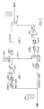
- the prior art feed-forward linearisation system comprises a comparison loop, designated LOOP1, in which a main amplifier amp1 in a main path extends in parallel with a reference path including a delay line dell.
- the main and reference paths each receive an input signal inpl.
- the amplifier amp1 produces a distorted output signal outp1.
- the reference path with the delay line del introduces a delay substantially equal to that of the amplifier amp1 to produce a delayed input1 delinpl.
- a comparator comp1 receives the signals outp1 and delinp1 and produces at its output an error signal err1 representative of the difference between the signals outp1 and delinp1. If the comparison loop LOOP1 is balanced, the error signal err1 is representative of distortion produced by the amplifier amp1.
- the error signal err1 is fed via amplitude and phase matching networks, not shown, to an error amplifier amp2 and thence to a first input of a combiner comb.
- the output outp1 of the amplifier amp1 is also fed to a second input of the combiner comb via a delay line del2 introducing a delay substantially equal to that introduced by comparator comp1 and the above mentioned amplitude and phase matching networks.
- the main amplifier amp1 path fulfills the need to have the same gain and phase shift as a reference path in order to subtract the distortion created in the main power amplifier amp1.
- the error amplifier path fulfills the need to have the same gain and phase shift as the main path so that the error can be subtracted from the error contained in the main power amplifier signal.
- Fig. 2 differs from Fig. 1 only by a phase control element phase1 and a gain control element gain1 having been introduced in series with the input of the amplifier amp1, and a phase control element phase2 and a gain control element gain2 having been introduced in series with the input of the amplifier amp2.
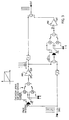
- Fig. 3 Another prior art method for control in the Cartesian domain of gain and phase is roughly indicated in Fig. 3 , that differs from Fig. 1 in the following respects.
- the input signal inp1 is coupled to the main amplifier amp2 via a control circuit including, in series, a 90-degree phase splitter and a Cartesian phase and gain control element.
- the 90-degree phase splitter receives the signal inp1 and splits it into two orthogonal components 0 and -90 received by the Cartesian phase and gain control element.
- the Cartesian phase and gain control element 4 is controlled by control signals I and Q.
- An arrangement similar to the above mentioned control circuit is also introduced before the amplifier amp2.
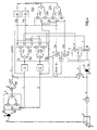
- FIG. 4 An embodiment of the present invention is shown in Figure 4 in the form of a feedforward linearisation system being phase and gain controlled in the Cartesian domain.
- An input signal A from a signal source 1 is split into signals B and C by a signal splitter Al.
- Signal C is delayed by a delay line 2 for use as a reference signal, as will also be described more closely below.
- Signal B is coupled to a main amplifier path including, in series, a 90-degree phase splitter 3, a Cartesian phase and control element 4 and a main amplifier 5.
- the 90-degree phase splitter 3 receives signal B and splits it into two orthogonal components BI and BQ received by the Cartesian phase and gain control element 4.
- the output of the control element 4 is fed to the main amplifier 5 that produces an output signal E.
- a fraction F of the main amplifier output signal E and the delayed signal C are fed to a subtracting circuit 7 that generates a difference G of signal E and the reference signal C.
- Reference vectors CI, CQ in the form of orthogonal components of the reference signal C are generated in a 90-degree phase splitter 8.
- the orthogonal components CI and CQ are fed to a first input of each a correlator 9 and 10, respectively, which also receive the signal G on a respective second input.
- the correlators 9 and 10 in their simplest form may be multipliers and perform correlation of the signal G with the orthogonal components CI and CQ for producing error vectors H and J.
- the orthogonal error vectors H and J are received in a rotator 11 for rotation therein and then control the Cartesian phase and gain element 4 via loop filters 12 and 13 as will be described more closely below. Thereby a control loop is closed.
- the rotation of the error vectors H and J makes the system unconditionally stable, independent of the phase difference between the main amplifier path B and the reference path C. In the present invention this is accomplished by measuring the phase shift of the loop containing the main amplifier 5, either directly or indirectly, and this information is then used to rotate the co-ordinate system accordingly.
- the transmitted phase being the phase between the Cartesian gain and phase controller 4 and the input of amplifier 5, may be indirectly determined by utilising the control signals Q and I for the gain and phase controller 4.
- the received phase being the phase at the input of the signal F at the subtracting circuit 7, is obtained by projecting the signal F on the reference vectors CI and CQ. This is performed in phase detectors 21, 22 which receive the signal F on each a first input and each one of the reference vectors CI and CQ on each a second input. Outputs 21a and 22a from the phase detectors 21 and 22, respectively, are fed to a phase subtractor 23 in which the difference between the transmitted and the received phase is calculated.
- the phase subtractor 23 comprises two groups 23a and 23b of each two phase detectors 23a1, 23a2 and 23b1, 23b2, respectively.
- the phase detectors 23a1 and 23b1 on one input each receive output 22a from the phase detector 22.
- the phase detectors 23a2 and 23b2 on one input each receive output 21a from the phase detector 21.
- the respective second inputs of phase detectors 23al and 23b2 are together connected to an output of the loop filter 12.
- the respective second inputs of phase detectors 23a2 and 23b2 are together connected to an output of the loop filter 13.
- Outputs of phase detectors 23al and 23a2 are added to form an input to a loop filter 25, the output of which forms a first input to the rotator 11.
- Outputs of phase detectors 23bl and 23b2 are subtracted to form an input to a loop filter 24, the output of which forms a second input to the rotator 11.
- the rotator 11 comprises two groups 11a and 11b of each two multipliers 11a1, 11a2 and 11b1, 11b2, respectively.
- the multipliers 11a1 and 11b1 on one input each receive output 25a from the loop filter 25.
- the multipliers 11a2 and 11b2 on one input each receive output 24a from the loop filter 2.
- the respective other inputs of multipliers 11a1 and 11b2 recieve the vector H from the correlator 9.
- the respective other inputs of multipliers 11a2 and 11b1 recieve the vector J from the correlator 10.
- Outputs of multipliers 11a1 and 11a2 are subtracted to form an input to the filter 12.
- Outputs of multipliers 11b1 and 11b2 are added to form an input to the filter 13.
- phase measurement as well as the co-ordinate system rotation can be performed in several places in the system and Figure 4 should be seen as one example. It is obvious, for example, that the co-ordinate system rotation can be made directly on the control signals Q and I, i.e. the rotator 11 may be located after the filters 12 and 13. Other examples are rotation on any of the RF signals involved, e.g. the reference signal C as illustrated in Fig. 5 , the signal E from the main amplifier 5, the signal F from the main amplifier going to the summation point 7 as illustrated in Fig. 6 , or the signal G forming the output of the summation point 7 as illustrated in Fig. 7 . In the same manner the phase difference can be measured in various ways, directly or indirectly as illustrated above.
- Figs. 5-7 have in common that they lack the rotator 11 of Fig. 4 and that the the error vectors H and J proceed directly to filters 12 and 13, respectively.
- signal C is splitted in a 90-degree phase splitter 26 into two orthogonal components used in a Cartesian phase and gain control element 27 as controlled by signals 24a and 25a from filters 24 and 25, respectively.
- the output of the control element 27 is received in the phase splitter 8.
- signal F is splitted in a 90-degree phase splitter 28 into two orthogonal components used in a Cartesian phase and gain control element 29 as controlled by signals 24a and 25a from filters 24 and 25, respectively.
- the output of the control element 29 is received in the upper input of the subtracting circuit 7.
- signal G is splitted in a 90-degree phase splitter 30 into two orthogonal components used in a Cartesian phase and gain control element 31 as controlled by signals 24a and 25a from filters 24 and 25, respectively.
- the output of the control element 31 is received in the common, upper inputs of the correlators 9 and 10 which produce the error vectors H and J received in filters 12 and 13, respectively.
- control loop can also be used to suppress distortion produced in the main amplifier loop since distortion can be seen as the result of signal-induced changes in the amplifier characteristics.
Landscapes
- Physics & Mathematics (AREA)
- Nonlinear Science (AREA)
- Engineering & Computer Science (AREA)
- Power Engineering (AREA)
- Amplifiers (AREA)
- Braking Systems And Boosters (AREA)
- Gripping On Spindles (AREA)
- Networks Using Active Elements (AREA)
Claims (18)
- Ein Verfahren zum automatischen Steuern der Phase in einem linearisierten elektronischen Verstärker, bildend einen Hauptverstärkerpfad, empfangend ein Signal von einer Signalquelle und mit einer Hauptausgabe, umfassend
Teilen des Signals (1) von der Signalquelle (A) in ein Hauptsignal (B), das an den Hauptverstärkerpfad (3, 4, 5) geht, und ein Referenzsignal (C), wobei das Haupt- und Referenzsignal (B, C) einen Phasenunterschied aufweisen,
Phasenteilen des Hauptsignals (B) in erste orthogonale Vektorkomponenten (BI/BQ), und
Phasenteilen des Referenzsignals (C) in zweite orthogonale Vektorkomponenten (C1/CQ),
wobei die Vektorkomponenten Teil eines kartesischen Systems bilden,
Messen des Phasenunterschieds zwischen dem Hauptsignal (B) und dem Referenzsignal (C), und
Stabilisieren des kartesischen Systems durch Rotieren des kartesischen Systems wie gesteuert durch den Phasenunterschied, und dabei Minimieren des Phasenunterschieds,
gekennzeichnet durch
Empfangen in einem Kartesischen-Phasen- und Verstärkungssteuerelement (4) in dem Hauptverstärkerpfad (3, 4, 5) der ersten orthogonalen Vektorkomponenten (BQ, BI), und Produzieren daraus eine ausgehende Phase des Hauptsignals (B),
Produzieren von Steuersignalen (I, Q) zum Steuern des Kartesischen-Phasen- und Verstärkungssteuerelements (4),
Bestimmen mittels eines Kartesischen-Phasen-Detektors (21, 22) eines Phasenunterschieds zwischen dem Referenzsignal (C) und einem Teilsignal (F), wobei das Teilsignal (F) einen Teil eines Hauptverstärker-Ausgangssignals (E) ist,
Ausführen des Messens an dem Phasenunterschied zwischen der Phase der Steuersignale (I, Q) und der Phase, die erhalten wird mit dem Kartesischen-Phasen-Detektor (21, 22). - Ein Verfahren nach Anspruch 1, gekennzeichnet durch Produzieren eines Unterschiedssignals (G) des Ausgangssignals von dem Hauptverstärker (5) und dem Referenzsignal (C),
Korrelieren der zweiten orthogonalen Vektorkomponenten (CI, CQ) und des Unterschiedssignals (G) zum Produzieren von Fehlervektoren (H, J) als Eingabevariablen an das Rotiermittel (11) zum Ausführen einer Rotation zum Produzieren der Steuersignale (I, Q). - Ein Verfahren nach einem der Ansprüche 1-2, gekennzeichnet durch Ausführen der Rotation hinsichtlich einem Funkfrequenz-(RF)-Signal (E) in dem Hauptverstärkerpfad (3, 4, 5).
- Ein Verfahren nach einem der Ansprüche 1-3, gekennzeichnet durch Ausführen der Rotation hinsichtlich der Phase des Referenzsignals (C).
- Ein Verfahren nach Anspruch 4, gekennzeichnet durch Phasenteilen des Referenzsignals in dritte orthogonale Vektorkomponenten, Korrelieren der dritten orthogonalen Vektorkomponenten zum Produzieren einer Eingabe an das zweite Phasenteilmittel (8).
- Ein Verfahren nach Anspruch 1, gekennzeichnet durch Ausführen der Rotation hinsichtlich des Teilsignals (F), gerichtet von der Ausgabe des Hauptverstärkers auf einen Summierungspunkt (7) für dieses Signal und das Referenzsignal.
- Ein Verfahren nach Anspruch 6, gekennzeichnet durch Phasenteilen des Referenzsignals (F), gerichtet von dem Ausgang des Hauptverstärkers in vierte orthogonale Vektorkomponenten, Korrelieren der vierten orthogonalen Vektorkomponenten zum Produzieren einer Eingabe an den Summierungspunkt (7).
- Ein Verfahren nach Anspruch 2, gekennzeichnet durch Ausführen der Rotation hinsichtlich eines Fehlersignals (G), Bereitstellen des Unterschieds zwischen dem Ausgangssignal des Verstärkers (E) und dem Referenzsignal (C).
- Ein Verfahren nach Anspruch 8, gekennzeichnet durch Phasenteilen des Fehlersignals (G) in fünfte orthogonale Vektorkomponenten, Korrelieren der fünften orthogonalen Vektorkomponenten zum Produzieren einer Eingabe an das Korreliermittel (9, 10) zum Empfangen und Korrelieren der zweiten orthogonalen Vektoren und des Unterschiedssignals (G) zum Produzieren von Fehlervektoren.
- Ein System zum automatischen Steuern der Phase in einem linearisierten elektronischen Verstärker (3, 4, 5), bildend einen Hauptverstärkerpfad, empfangend ein Signal (A) von einer Signalquelle (1) und mit einer Hauptausgabe (E), umfassend
Signalteilmittel (A1) zum Teilen des Signals (1) von der Signalquelle (A) in ein Hauptsignal (B), das an den Hauptverstärkerpfad (3, 4, 5) geht, und ein Referenzsignal (C), wobei das Haupt- und Referenzsignal (B, C) einen Phasenunterschied aufweisen,
erste Phasenteilmittel (3) zum Phasenteilen des Hauptsignals (B) in erste orthogonale Vektorkomponenten (BI/BQ), und zweite Phasenteilmittel (8) zum Phasenteilen des Referenzsignals (C) in zweite orthogonale Vektorkomponenten (Cl/CQ),
wobei die Vektorkomponenten einen Teil eines kartesischen Systems bilden, Mittel (21, 22, 23) zum Messen des Phasenunterschieds zwischen dem Hauptsignal (B) und dem Referenzsignal (C), und
Rotiermittel (11; 27; 29; 31) zum Stabilisieren des kartesischen Systems durch Rotieren des kartesischen Systems wie gesteuert durch den Phasenunterschied, und dabei Minimieren des Phasenunterschieds,
gekennzeichnet durch
ein Kartesische-Phasen- und Verstärkungssteuerelement (4) in dem Hauptverstärkerpfad (3, 4, 5) zum Empfangen der ersten orthogonalen Vektorkomponenten (BQ, BI), und Produzieren davon eine ausgehende Phase des Hauptsignals (B),
Mittel (9, 10, 11, 12, 13) zum Produzieren von Steuersignalen (I, Q) zum Steuern des Kartesischen-Phasen- und Verstärkungssteuerelements (4),
ein Kartesische-Phasen-Detektor (21, 22) zum Bestimmen eines Phasenunterschieds zwischen dem Referenzsignal (C) und einem Teilsignal (F), wobei das Teilsignal (F) einen Teil eines Hauptverstärker-Ausgangssignals (E) ist,
Mittel (22) zum Ausführen des Messens an dem Phasenunterschied zwischen der Phase der Steuersignale (I, Q) und der Phase, die erhalten wird mit dem Kartesischen-Phasen-Detektor (21, 22). - Ein System nach Anspruch 10, gekennzeichnet durch Mittel (7) zum Produzieren eines Unterschiedssignals (G) des Ausgangssignals von dem Hauptverstärker (5) und dem Referenzsignal (C),
Korreliermittel (9, 10) zum Empfangen und Korrelieren der zweiten orthogonalen Vektorkomponenten (CI, CQ) und des Unterschiedssignals (G) zum Produzieren von Fehlervektoren (H, J) als Eingabevariablen an das Rotiermittel (11) zum Ausführen einer Rotation daran zum Produzieren der Steuersignale (I, Q). - Ein System nach einem der Ansprüche 10-11, dadurch gekennzeichnet, dass das Rotiermittel (11) die Rotation hinsichtlich einem Funkfrequenz-(RF)-Signal (E) in dem Hauptverstärkerpfad (3, 4, 5) ausführt.
- Ein System nach einem der Ansprüche 10-12, dadurch gekennzeichnet, dass das Rotiermittel die Rotation hinsichtlich der Phase des Referenzsignals (C) ausführt.
- Ein System nach Anspruch 13, gekennzeichnet durch dritte Phasenteilmittel (26) für ein Phasenteilen des Referenzsignals (C) in dritte orthogonale Vektorkomponenten, Korreliermittel (27) zum Empfangen und Korrelieren der dritten orthogonalen Vektorkomponenten zum Produzieren einer Eingabe an das zweite Phasenteilmittel (8).
- Ein System nach Anspruch 10, dadurch gekennzeichnet, dass das Rotiermittel die Rotation hinsichtlich des Teilsignals (F) ausführt, gerichtet von der Ausgabe des Hauptverstärkers auf einen Summierungspunkt (7) für dieses Signal und das Referenzsignal.
- Ein System nach Anspruch 11, gekennzeichnet durch vierte Phasenteilmittel (28) für ein Phasenteilen des Teilsignals (F), gerichtet von dem Ausgang des Hauptverstärkers in vierte orthogonale Vektorkomponenten, Korreliermittel (29) zum Empfangen und Korrelieren der vierten orthogonalen Vektorkomponenten zum Produzieren einer Eingabe an den Summierungspunkt (7).
- Ein System nach Anspruch 11, dadurch gekennzeichnet, dass das Rotiermittel die Rotation hinsichtlich eines Fehlersignals (G) ausführt, was den Unterschied bereitstellt zwischen dem Ausgangssignal des Verstärkers (E) und dem Referenzsignal (C).
- Ein System nach Anspruch 17, gekennzeichnet durch fünfte Phasenteilmittel (30) für ein Phasenteilen des Fehlersignals (G) in fünfte orthogonale Vektorkomponenten, fünfte Korreliermittel (31) zum Empfangen und Korrelieren der fünften orthogonalen Vektorkomponenten zum Produzieren einer Eingabe an das Korrelier (9, 10) zum Empfangen und Korrelieren der zweiten orthogonalen Vektoren und des Unterschiedssignals (G) zum Produzieren von Fehlervektoren.
Applications Claiming Priority (3)
| Application Number | Priority Date | Filing Date | Title |
|---|---|---|---|
| SE9903917A SE519596C2 (sv) | 1999-10-29 | 1999-10-29 | Metod och apparat för att styra fasen i en lineariserad elektronisk förstärkare |
| SE9903917 | 1999-10-29 | ||
| PCT/SE2000/002086 WO2001031779A1 (en) | 1999-10-29 | 2000-10-26 | Amplifier stabilisation |
Publications (2)
| Publication Number | Publication Date |
|---|---|
| EP1234376A1 EP1234376A1 (de) | 2002-08-28 |
| EP1234376B1 true EP1234376B1 (de) | 2008-08-13 |
Family
ID=20417538
Family Applications (1)
| Application Number | Title | Priority Date | Filing Date |
|---|---|---|---|
| EP00975108A Expired - Lifetime EP1234376B1 (de) | 1999-10-29 | 2000-10-26 | Verstärkerstabilisierung |
Country Status (11)
| Country | Link |
|---|---|
| US (1) | US6727750B1 (de) |
| EP (1) | EP1234376B1 (de) |
| JP (1) | JP4050054B2 (de) |
| CN (1) | CN1160849C (de) |
| AT (1) | ATE405030T1 (de) |
| AU (1) | AU770576B2 (de) |
| CA (1) | CA2386929C (de) |
| DE (1) | DE60039906D1 (de) |
| ES (1) | ES2311477T3 (de) |
| SE (1) | SE519596C2 (de) |
| WO (1) | WO2001031779A1 (de) |
Families Citing this family (1)
| Publication number | Priority date | Publication date | Assignee | Title |
|---|---|---|---|---|
| US6680649B2 (en) | 2002-06-07 | 2004-01-20 | Telefonaktiebolaget Lm Ericsson (Publ) | Coordinate rotation of pre-distortion vector in feedforward linearization amplification system |
Family Cites Families (4)
| Publication number | Priority date | Publication date | Assignee | Title |
|---|---|---|---|---|
| US5420536A (en) * | 1993-03-16 | 1995-05-30 | Victoria University Of Technology | Linearized power amplifier |
| US5574967A (en) * | 1994-01-11 | 1996-11-12 | Ericsson Ge Mobile Communications, Inc. | Waste energy control and management in power amplifiers |
| SE512623C2 (sv) * | 1997-11-03 | 2000-04-10 | Ericsson Telefon Ab L M | Förfarande och anordning i ett telekommunikationsproblem |
| US6359508B1 (en) * | 2000-08-17 | 2002-03-19 | Spectrian Corporation | Distortion detection apparatus for controlling predistortion, carrier cancellation and feed-forward cancellation in linear RF power amplifiers |
-
1999
- 1999-10-29 SE SE9903917A patent/SE519596C2/sv not_active IP Right Cessation
-
2000
- 2000-10-26 CA CA2386929A patent/CA2386929C/en not_active Expired - Fee Related
- 2000-10-26 AU AU13205/01A patent/AU770576B2/en not_active Ceased
- 2000-10-26 EP EP00975108A patent/EP1234376B1/de not_active Expired - Lifetime
- 2000-10-26 AT AT00975108T patent/ATE405030T1/de not_active IP Right Cessation
- 2000-10-26 JP JP2001533621A patent/JP4050054B2/ja not_active Expired - Fee Related
- 2000-10-26 WO PCT/SE2000/002086 patent/WO2001031779A1/en not_active Ceased
- 2000-10-26 CN CNB008150222A patent/CN1160849C/zh not_active Expired - Fee Related
- 2000-10-26 DE DE60039906T patent/DE60039906D1/de not_active Expired - Lifetime
- 2000-10-26 ES ES00975108T patent/ES2311477T3/es not_active Expired - Lifetime
- 2000-10-27 US US09/697,475 patent/US6727750B1/en not_active Expired - Lifetime
Also Published As
| Publication number | Publication date |
|---|---|
| SE9903917L (sv) | 2001-04-30 |
| SE519596C2 (sv) | 2003-03-18 |
| JP2003513499A (ja) | 2003-04-08 |
| CA2386929A1 (en) | 2001-05-03 |
| CA2386929C (en) | 2011-10-18 |
| CN1384997A (zh) | 2002-12-11 |
| SE9903917D0 (sv) | 1999-10-29 |
| US6727750B1 (en) | 2004-04-27 |
| ATE405030T1 (de) | 2008-08-15 |
| WO2001031779A1 (en) | 2001-05-03 |
| EP1234376A1 (de) | 2002-08-28 |
| AU770576B2 (en) | 2004-02-26 |
| AU1320501A (en) | 2001-05-08 |
| ES2311477T3 (es) | 2009-02-16 |
| JP4050054B2 (ja) | 2008-02-20 |
| CN1160849C (zh) | 2004-08-04 |
| DE60039906D1 (de) | 2008-09-25 |
Similar Documents
| Publication | Publication Date | Title |
|---|---|---|
| US6859099B2 (en) | Nonlinear distortion compensation power amplifier | |
| JP3342018B2 (ja) | 適応型予歪付与回路を有するrfアンプ | |
| US6606483B1 (en) | Dual open and closed loop linear transmitter | |
| EP2766988B1 (de) | Steuerungssystem für einen leistungsverstärker | |
| US5789976A (en) | Digital adaptive control of feedforward amplifier using frequency domain cancellation | |
| EP0899870A1 (de) | Gerät und Verfahren zur Vorverzerrungskorrektur eines Leistungsverstärkers | |
| JP2002506307A (ja) | 前置補償器 | |
| PL183774B1 (pl) | Sposób i urządzenie do nadawania transmisji radiowej | |
| KR100438445B1 (ko) | 비선형 왜곡 보상 방법 및 비선형 왜곡 보상 회로 | |
| JP2002319870A (ja) | ループゲイン制御方法及び電力増幅回路 | |
| US6081156A (en) | Method and apparatus for amplifying feedforward linear power using pilot tone hopping | |
| US5781069A (en) | Pre-post distortion amplifier | |
| US7187234B2 (en) | Decorrelated power amplifier linearizers | |
| JPH10511534A (ja) | 無線周波数通信システムにおいて使用する増幅回路および増幅器の制御方法 | |
| GB2107540A (en) | Feedforward amplifiers | |
| US5473460A (en) | Adaptive equalizer for analog optical signal transmission | |
| JP2002506305A (ja) | 前置補償器 | |
| US6326840B1 (en) | Feed-forward distortion compensation amplifier and method of amplifying signal with feed-forward distortion compensation | |
| EP1234376B1 (de) | Verstärkerstabilisierung | |
| JP2003198273A (ja) | 増幅回路 | |
| KR20020070572A (ko) | 지연선로를 이용한 선형화기를 갖는 선형전력증폭기 | |
| JP3160081B2 (ja) | 歪み補償回路 | |
| CN100449938C (zh) | 前馈线性功率放大器误差环自适应对消控制方法 | |
| JP2001333124A (ja) | Dcオフセット調整方法及びそれを用いた負帰還増幅器 | |
| KR20010010892A (ko) | 통신시스템에서의 개선된 왜곡 신호 보상 장치 |
Legal Events
| Date | Code | Title | Description |
|---|---|---|---|
| PUAI | Public reference made under article 153(3) epc to a published international application that has entered the european phase |
Free format text: ORIGINAL CODE: 0009012 |
|
| 17P | Request for examination filed |
Effective date: 20020419 |
|
| AK | Designated contracting states |
Kind code of ref document: A1 Designated state(s): AT BE CH CY DE DK ES FI FR GB GR IE IT LI LU MC NL PT SE |
|
| AX | Request for extension of the european patent |
Free format text: AL;LT;LV;MK;RO;SI |
|
| RAP1 | Party data changed (applicant data changed or rights of an application transferred) |
Owner name: TELEFONAKTIEBOLAGET LM ERICSSON (PUBL) |
|
| 17Q | First examination report despatched |
Effective date: 20070226 |
|
| GRAP | Despatch of communication of intention to grant a patent |
Free format text: ORIGINAL CODE: EPIDOSNIGR1 |
|
| GRAS | Grant fee paid |
Free format text: ORIGINAL CODE: EPIDOSNIGR3 |
|
| GRAA | (expected) grant |
Free format text: ORIGINAL CODE: 0009210 |
|
| AK | Designated contracting states |
Kind code of ref document: B1 Designated state(s): AT BE CH CY DE DK ES FI FR GB GR IE IT LI LU MC NL PT SE |
|
| REG | Reference to a national code |
Ref country code: GB Ref legal event code: FG4D |
|
| REG | Reference to a national code |
Ref country code: CH Ref legal event code: EP |
|
| REG | Reference to a national code |
Ref country code: IE Ref legal event code: FG4D |
|
| REF | Corresponds to: |
Ref document number: 60039906 Country of ref document: DE Date of ref document: 20080925 Kind code of ref document: P |
|
| PG25 | Lapsed in a contracting state [announced via postgrant information from national office to epo] |
Ref country code: NL Free format text: LAPSE BECAUSE OF FAILURE TO SUBMIT A TRANSLATION OF THE DESCRIPTION OR TO PAY THE FEE WITHIN THE PRESCRIBED TIME-LIMIT Effective date: 20080813 |
|
| REG | Reference to a national code |
Ref country code: ES Ref legal event code: FG2A Ref document number: 2311477 Country of ref document: ES Kind code of ref document: T3 |
|
| PG25 | Lapsed in a contracting state [announced via postgrant information from national office to epo] |
Ref country code: AT Free format text: LAPSE BECAUSE OF FAILURE TO SUBMIT A TRANSLATION OF THE DESCRIPTION OR TO PAY THE FEE WITHIN THE PRESCRIBED TIME-LIMIT Effective date: 20080813 Ref country code: FI Free format text: LAPSE BECAUSE OF FAILURE TO SUBMIT A TRANSLATION OF THE DESCRIPTION OR TO PAY THE FEE WITHIN THE PRESCRIBED TIME-LIMIT Effective date: 20080813 |
|
| PG25 | Lapsed in a contracting state [announced via postgrant information from national office to epo] |
Ref country code: BE Free format text: LAPSE BECAUSE OF FAILURE TO SUBMIT A TRANSLATION OF THE DESCRIPTION OR TO PAY THE FEE WITHIN THE PRESCRIBED TIME-LIMIT Effective date: 20080813 |
|
| PG25 | Lapsed in a contracting state [announced via postgrant information from national office to epo] |
Ref country code: DK Free format text: LAPSE BECAUSE OF FAILURE TO SUBMIT A TRANSLATION OF THE DESCRIPTION OR TO PAY THE FEE WITHIN THE PRESCRIBED TIME-LIMIT Effective date: 20080813 |
|
| PG25 | Lapsed in a contracting state [announced via postgrant information from national office to epo] |
Ref country code: MC Free format text: LAPSE BECAUSE OF NON-PAYMENT OF DUE FEES Effective date: 20081031 Ref country code: PT Free format text: LAPSE BECAUSE OF FAILURE TO SUBMIT A TRANSLATION OF THE DESCRIPTION OR TO PAY THE FEE WITHIN THE PRESCRIBED TIME-LIMIT Effective date: 20090113 |
|
| REG | Reference to a national code |
Ref country code: CH Ref legal event code: PL |
|
| PLBE | No opposition filed within time limit |
Free format text: ORIGINAL CODE: 0009261 |
|
| STAA | Information on the status of an ep patent application or granted ep patent |
Free format text: STATUS: NO OPPOSITION FILED WITHIN TIME LIMIT |
|
| 26N | No opposition filed |
Effective date: 20090514 |
|
| REG | Reference to a national code |
Ref country code: FR Ref legal event code: ST Effective date: 20090630 |
|
| PG25 | Lapsed in a contracting state [announced via postgrant information from national office to epo] |
Ref country code: IT Free format text: LAPSE BECAUSE OF FAILURE TO SUBMIT A TRANSLATION OF THE DESCRIPTION OR TO PAY THE FEE WITHIN THE PRESCRIBED TIME-LIMIT Effective date: 20080813 |
|
| PG25 | Lapsed in a contracting state [announced via postgrant information from national office to epo] |
Ref country code: FR Free format text: LAPSE BECAUSE OF NON-PAYMENT OF DUE FEES Effective date: 20081031 Ref country code: CH Free format text: LAPSE BECAUSE OF NON-PAYMENT OF DUE FEES Effective date: 20081031 Ref country code: LI Free format text: LAPSE BECAUSE OF NON-PAYMENT OF DUE FEES Effective date: 20081031 Ref country code: IE Free format text: LAPSE BECAUSE OF NON-PAYMENT OF DUE FEES Effective date: 20081026 |
|
| PG25 | Lapsed in a contracting state [announced via postgrant information from national office to epo] |
Ref country code: SE Free format text: LAPSE BECAUSE OF FAILURE TO SUBMIT A TRANSLATION OF THE DESCRIPTION OR TO PAY THE FEE WITHIN THE PRESCRIBED TIME-LIMIT Effective date: 20081113 |
|
| PG25 | Lapsed in a contracting state [announced via postgrant information from national office to epo] |
Ref country code: LU Free format text: LAPSE BECAUSE OF NON-PAYMENT OF DUE FEES Effective date: 20081026 Ref country code: CY Free format text: LAPSE BECAUSE OF FAILURE TO SUBMIT A TRANSLATION OF THE DESCRIPTION OR TO PAY THE FEE WITHIN THE PRESCRIBED TIME-LIMIT Effective date: 20080813 |
|
| PG25 | Lapsed in a contracting state [announced via postgrant information from national office to epo] |
Ref country code: GR Free format text: LAPSE BECAUSE OF FAILURE TO SUBMIT A TRANSLATION OF THE DESCRIPTION OR TO PAY THE FEE WITHIN THE PRESCRIBED TIME-LIMIT Effective date: 20081114 |
|
| REG | Reference to a national code |
Ref country code: ES Ref legal event code: PC2A Owner name: UNWIRED PLANET INTERNATIONAL LIMITED Effective date: 20140902 |
|
| REG | Reference to a national code |
Ref country code: DE Ref legal event code: R082 Ref document number: 60039906 Country of ref document: DE Representative=s name: DF-MP DOERRIES FRANK-MOLNIA & POHLMAN PATENTAN, DE |
|
| REG | Reference to a national code |
Ref country code: GB Ref legal event code: 732E Free format text: REGISTERED BETWEEN 20141030 AND 20141105 |
|
| REG | Reference to a national code |
Ref country code: DE Ref legal event code: R082 Ref document number: 60039906 Country of ref document: DE Representative=s name: DF-MP DOERRIES FRANK-MOLNIA & POHLMAN PATENTAN, DE Effective date: 20141029 Ref country code: DE Ref legal event code: R081 Ref document number: 60039906 Country of ref document: DE Owner name: UNWIRED PLANET LLC, RENO, US Free format text: FORMER OWNER: TELEFONAKTIEBOLAGET LM ERICSSON (PUBL), STOCKHOLM, SE Effective date: 20141029 Ref country code: DE Ref legal event code: R081 Ref document number: 60039906 Country of ref document: DE Owner name: UNWIRED PLANET INTERNATIONAL LTD., IE Free format text: FORMER OWNER: TELEFONAKTIEBOLAGET LM ERICSSON (PUBL), STOCKHOLM, SE Effective date: 20141029 |
|
| REG | Reference to a national code |
Ref country code: DE Ref legal event code: R082 Ref document number: 60039906 Country of ref document: DE Representative=s name: DF-MP DOERRIES FRANK-MOLNIA & POHLMAN PATENTAN, DE |
|
| REG | Reference to a national code |
Ref country code: DE Ref legal event code: R082 Ref document number: 60039906 Country of ref document: DE Representative=s name: DF-MP DOERRIES FRANK-MOLNIA & POHLMAN PATENTAN, DE Effective date: 20150323 Ref country code: DE Ref legal event code: R081 Ref document number: 60039906 Country of ref document: DE Owner name: UNWIRED PLANET INTERNATIONAL LTD., IE Free format text: FORMER OWNER: UNWIRED PLANET LLC, RENO, NEV., US Effective date: 20150323 |
|
| REG | Reference to a national code |
Ref country code: GB Ref legal event code: 732E Free format text: REGISTERED BETWEEN 20150618 AND 20150624 |
|
| PGFP | Annual fee paid to national office [announced via postgrant information from national office to epo] |
Ref country code: GB Payment date: 20170925 Year of fee payment: 18 |
|
| PGFP | Annual fee paid to national office [announced via postgrant information from national office to epo] |
Ref country code: DE Payment date: 20170920 Year of fee payment: 18 |
|
| PGFP | Annual fee paid to national office [announced via postgrant information from national office to epo] |
Ref country code: ES Payment date: 20171103 Year of fee payment: 18 |
|
| REG | Reference to a national code |
Ref country code: GB Ref legal event code: 732E Free format text: REGISTERED BETWEEN 20180510 AND 20180516 |
|
| REG | Reference to a national code |
Ref country code: DE Ref legal event code: R119 Ref document number: 60039906 Country of ref document: DE |
|
| GBPC | Gb: european patent ceased through non-payment of renewal fee |
Effective date: 20181026 |
|
| PG25 | Lapsed in a contracting state [announced via postgrant information from national office to epo] |
Ref country code: DE Free format text: LAPSE BECAUSE OF NON-PAYMENT OF DUE FEES Effective date: 20190501 |
|
| PG25 | Lapsed in a contracting state [announced via postgrant information from national office to epo] |
Ref country code: GB Free format text: LAPSE BECAUSE OF NON-PAYMENT OF DUE FEES Effective date: 20181026 |
|
| REG | Reference to a national code |
Ref country code: ES Ref legal event code: FD2A Effective date: 20191203 |
|
| PG25 | Lapsed in a contracting state [announced via postgrant information from national office to epo] |
Ref country code: ES Free format text: LAPSE BECAUSE OF NON-PAYMENT OF DUE FEES Effective date: 20181027 |