EP1234553A1 - Dispositif bioartificiel - Google Patents
Dispositif bioartificiel Download PDFInfo
- Publication number
- EP1234553A1 EP1234553A1 EP01103420A EP01103420A EP1234553A1 EP 1234553 A1 EP1234553 A1 EP 1234553A1 EP 01103420 A EP01103420 A EP 01103420A EP 01103420 A EP01103420 A EP 01103420A EP 1234553 A1 EP1234553 A1 EP 1234553A1
- Authority
- EP
- European Patent Office
- Prior art keywords
- reactor vessel
- cell culture
- hose
- chamber
- plasma
- Prior art date
- Legal status (The legal status is an assumption and is not a legal conclusion. Google has not performed a legal analysis and makes no representation as to the accuracy of the status listed.)
- Withdrawn
Links
- 238000004113 cell culture Methods 0.000 claims abstract description 28
- 210000004369 blood Anatomy 0.000 claims abstract description 22
- 239000008280 blood Substances 0.000 claims abstract description 22
- 235000015097 nutrients Nutrition 0.000 claims abstract description 19
- 239000000463 material Substances 0.000 claims abstract description 6
- 230000003908 liver function Effects 0.000 claims description 6
- 238000003756 stirring Methods 0.000 claims description 6
- 238000012360 testing method Methods 0.000 claims description 6
- 230000017531 blood circulation Effects 0.000 claims description 5
- 230000002093 peripheral effect Effects 0.000 claims description 5
- 239000000969 carrier Substances 0.000 claims description 2
- 210000005229 liver cell Anatomy 0.000 abstract description 5
- 238000006243 chemical reaction Methods 0.000 abstract description 3
- 210000004185 liver Anatomy 0.000 description 26
- 208000007788 Acute Liver Failure Diseases 0.000 description 20
- 206010000804 Acute hepatic failure Diseases 0.000 description 19
- 231100000836 acute liver failure Toxicity 0.000 description 18
- 239000002609 medium Substances 0.000 description 16
- 206010019663 Hepatic failure Diseases 0.000 description 11
- 241001465754 Metazoa Species 0.000 description 11
- 208000007903 liver failure Diseases 0.000 description 9
- 231100000835 liver failure Toxicity 0.000 description 9
- 208000014644 Brain disease Diseases 0.000 description 8
- 208000032274 Encephalopathy Diseases 0.000 description 8
- 210000004027 cell Anatomy 0.000 description 8
- 238000002616 plasmapheresis Methods 0.000 description 6
- 239000000725 suspension Substances 0.000 description 6
- 238000002054 transplantation Methods 0.000 description 6
- 206010023126 Jaundice Diseases 0.000 description 5
- 208000027418 Wounds and injury Diseases 0.000 description 5
- 230000000694 effects Effects 0.000 description 5
- 208000005252 hepatitis A Diseases 0.000 description 5
- 210000003494 hepatocyte Anatomy 0.000 description 5
- 206010048962 Brain oedema Diseases 0.000 description 4
- 206010053567 Coagulopathies Diseases 0.000 description 4
- 208000015294 blood coagulation disease Diseases 0.000 description 4
- 208000006752 brain edema Diseases 0.000 description 4
- CNQCVBJFEGMYDW-UHFFFAOYSA-N lawrencium atom Chemical compound [Lr] CNQCVBJFEGMYDW-UHFFFAOYSA-N 0.000 description 4
- 229920002981 polyvinylidene fluoride Polymers 0.000 description 4
- 230000004083 survival effect Effects 0.000 description 4
- 208000024891 symptom Diseases 0.000 description 4
- 230000003612 virological effect Effects 0.000 description 4
- RZVAJINKPMORJF-UHFFFAOYSA-N Acetaminophen Chemical compound CC(=O)NC1=CC=C(O)C=C1 RZVAJINKPMORJF-UHFFFAOYSA-N 0.000 description 3
- 206010019786 Hepatitis non-A non-B Diseases 0.000 description 3
- 206010019799 Hepatitis viral Diseases 0.000 description 3
- 206010022773 Intracranial pressure increased Diseases 0.000 description 3
- 230000001154 acute effect Effects 0.000 description 3
- 230000005540 biological transmission Effects 0.000 description 3
- 239000006285 cell suspension Substances 0.000 description 3
- 201000010099 disease Diseases 0.000 description 3
- 208000037265 diseases, disorders, signs and symptoms Diseases 0.000 description 3
- 230000001771 impaired effect Effects 0.000 description 3
- 208000015181 infectious disease Diseases 0.000 description 3
- 238000007917 intracranial administration Methods 0.000 description 3
- 210000000056 organ Anatomy 0.000 description 3
- 244000052769 pathogen Species 0.000 description 3
- 230000001717 pathogenic effect Effects 0.000 description 3
- 230000008929 regeneration Effects 0.000 description 3
- 238000011069 regeneration method Methods 0.000 description 3
- 201000001862 viral hepatitis Diseases 0.000 description 3
- QGZKDVFQNNGYKY-UHFFFAOYSA-N Ammonia Chemical compound N QGZKDVFQNNGYKY-UHFFFAOYSA-N 0.000 description 2
- OKTJSMMVPCPJKN-UHFFFAOYSA-N Carbon Chemical compound [C] OKTJSMMVPCPJKN-UHFFFAOYSA-N 0.000 description 2
- 208000037319 Hepatitis infectious Diseases 0.000 description 2
- 206010067125 Liver injury Diseases 0.000 description 2
- 208000034486 Multi-organ failure Diseases 0.000 description 2
- 206010030113 Oedema Diseases 0.000 description 2
- 208000005374 Poisoning Diseases 0.000 description 2
- 241000282887 Suidae Species 0.000 description 2
- QVGXLLKOCUKJST-UHFFFAOYSA-N atomic oxygen Chemical compound [O] QVGXLLKOCUKJST-UHFFFAOYSA-N 0.000 description 2
- 230000008901 benefit Effects 0.000 description 2
- 230000015572 biosynthetic process Effects 0.000 description 2
- 238000004140 cleaning Methods 0.000 description 2
- 208000009190 disseminated intravascular coagulation Diseases 0.000 description 2
- 230000006870 function Effects 0.000 description 2
- BTCSSZJGUNDROE-UHFFFAOYSA-N gamma-aminobutyric acid Chemical compound NCCCC(O)=O BTCSSZJGUNDROE-UHFFFAOYSA-N 0.000 description 2
- 239000007789 gas Substances 0.000 description 2
- 231100000234 hepatic damage Toxicity 0.000 description 2
- 208000007386 hepatic encephalopathy Diseases 0.000 description 2
- 208000002672 hepatitis B Diseases 0.000 description 2
- NOESYZHRGYRDHS-UHFFFAOYSA-N insulin Chemical compound N1C(=O)C(NC(=O)C(CCC(N)=O)NC(=O)C(CCC(O)=O)NC(=O)C(C(C)C)NC(=O)C(NC(=O)CN)C(C)CC)CSSCC(C(NC(CO)C(=O)NC(CC(C)C)C(=O)NC(CC=2C=CC(O)=CC=2)C(=O)NC(CCC(N)=O)C(=O)NC(CC(C)C)C(=O)NC(CCC(O)=O)C(=O)NC(CC(N)=O)C(=O)NC(CC=2C=CC(O)=CC=2)C(=O)NC(CSSCC(NC(=O)C(C(C)C)NC(=O)C(CC(C)C)NC(=O)C(CC=2C=CC(O)=CC=2)NC(=O)C(CC(C)C)NC(=O)C(C)NC(=O)C(CCC(O)=O)NC(=O)C(C(C)C)NC(=O)C(CC(C)C)NC(=O)C(CC=2NC=NC=2)NC(=O)C(CO)NC(=O)CNC2=O)C(=O)NCC(=O)NC(CCC(O)=O)C(=O)NC(CCCNC(N)=N)C(=O)NCC(=O)NC(CC=3C=CC=CC=3)C(=O)NC(CC=3C=CC=CC=3)C(=O)NC(CC=3C=CC(O)=CC=3)C(=O)NC(C(C)O)C(=O)N3C(CCC3)C(=O)NC(CCCCN)C(=O)NC(C)C(O)=O)C(=O)NC(CC(N)=O)C(O)=O)=O)NC(=O)C(C(C)CC)NC(=O)C(CO)NC(=O)C(C(C)O)NC(=O)C1CSSCC2NC(=O)C(CC(C)C)NC(=O)C(NC(=O)C(CCC(N)=O)NC(=O)C(CC(N)=O)NC(=O)C(NC(=O)C(N)CC=1C=CC=CC=1)C(C)C)CC1=CN=CN1 NOESYZHRGYRDHS-UHFFFAOYSA-N 0.000 description 2
- 230000035987 intoxication Effects 0.000 description 2
- 231100000566 intoxication Toxicity 0.000 description 2
- 230000008818 liver damage Effects 0.000 description 2
- 208000019423 liver disease Diseases 0.000 description 2
- 230000002503 metabolic effect Effects 0.000 description 2
- 238000000034 method Methods 0.000 description 2
- 208000029744 multiple organ dysfunction syndrome Diseases 0.000 description 2
- 229910052760 oxygen Inorganic materials 0.000 description 2
- 239000001301 oxygen Substances 0.000 description 2
- 208000012237 paracetamol poisoning Diseases 0.000 description 2
- 231100000572 poisoning Toxicity 0.000 description 2
- 230000000607 poisoning effect Effects 0.000 description 2
- 239000011148 porous material Substances 0.000 description 2
- 238000004393 prognosis Methods 0.000 description 2
- 230000011514 reflex Effects 0.000 description 2
- 238000010992 reflux Methods 0.000 description 2
- 229920006395 saturated elastomer Polymers 0.000 description 2
- VZGDMQKNWNREIO-UHFFFAOYSA-N tetrachloromethane Chemical compound ClC(Cl)(Cl)Cl VZGDMQKNWNREIO-UHFFFAOYSA-N 0.000 description 2
- 238000002560 therapeutic procedure Methods 0.000 description 2
- 238000011282 treatment Methods 0.000 description 2
- 238000004804 winding Methods 0.000 description 2
- OGNSCSPNOLGXSM-UHFFFAOYSA-N (+/-)-DABA Natural products NCCC(N)C(O)=O OGNSCSPNOLGXSM-UHFFFAOYSA-N 0.000 description 1
- WHTVZRBIWZFKQO-AWEZNQCLSA-N (S)-chloroquine Chemical compound ClC1=CC=C2C(N[C@@H](C)CCCN(CC)CC)=CC=NC2=C1 WHTVZRBIWZFKQO-AWEZNQCLSA-N 0.000 description 1
- GUJAGMICFDYKNR-UHFFFAOYSA-N 1,4-benzodiazepine Chemical class N1C=CN=CC2=CC=CC=C12 GUJAGMICFDYKNR-UHFFFAOYSA-N 0.000 description 1
- SVUOLADPCWQTTE-UHFFFAOYSA-N 1h-1,2-benzodiazepine Chemical compound N1N=CC=CC2=CC=CC=C12 SVUOLADPCWQTTE-UHFFFAOYSA-N 0.000 description 1
- 208000010444 Acidosis Diseases 0.000 description 1
- 206010059193 Acute hepatitis B Diseases 0.000 description 1
- 241000894006 Bacteria Species 0.000 description 1
- 208000035143 Bacterial infection Diseases 0.000 description 1
- 108010039209 Blood Coagulation Factors Proteins 0.000 description 1
- 102000015081 Blood Coagulation Factors Human genes 0.000 description 1
- 201000006474 Brain Ischemia Diseases 0.000 description 1
- 208000007257 Budd-Chiari syndrome Diseases 0.000 description 1
- 241000222122 Candida albicans Species 0.000 description 1
- 206010008120 Cerebral ischaemia Diseases 0.000 description 1
- 102100037529 Coagulation factor V Human genes 0.000 description 1
- 206010010071 Coma Diseases 0.000 description 1
- RYGMFSIKBFXOCR-UHFFFAOYSA-N Copper Chemical compound [Cu] RYGMFSIKBFXOCR-UHFFFAOYSA-N 0.000 description 1
- RWSOTUBLDIXVET-UHFFFAOYSA-N Dihydrogen sulfide Chemical class S RWSOTUBLDIXVET-UHFFFAOYSA-N 0.000 description 1
- 208000010334 End Stage Liver Disease Diseases 0.000 description 1
- 108010014172 Factor V Proteins 0.000 description 1
- UIOFUWFRIANQPC-JKIFEVAISA-N Floxacillin Chemical compound N([C@@H]1C(N2[C@H](C(C)(C)S[C@@H]21)C(O)=O)=O)C(=O)C1=C(C)ON=C1C1=C(F)C=CC=C1Cl UIOFUWFRIANQPC-JKIFEVAISA-N 0.000 description 1
- 206010017533 Fungal infection Diseases 0.000 description 1
- 241000233866 Fungi Species 0.000 description 1
- 208000000857 Hepatic Insufficiency Diseases 0.000 description 1
- 208000005176 Hepatitis C Diseases 0.000 description 1
- 208000002972 Hepatolenticular Degeneration Diseases 0.000 description 1
- 208000013016 Hypoglycemia Diseases 0.000 description 1
- 208000029663 Hypophosphatemia Diseases 0.000 description 1
- 206010021143 Hypoxia Diseases 0.000 description 1
- 206010062016 Immunosuppression Diseases 0.000 description 1
- 102000004877 Insulin Human genes 0.000 description 1
- 108090001061 Insulin Proteins 0.000 description 1
- 206010023025 Ischaemic hepatitis Diseases 0.000 description 1
- JVTAAEKCZFNVCJ-UHFFFAOYSA-M Lactate Chemical compound CC(O)C([O-])=O JVTAAEKCZFNVCJ-UHFFFAOYSA-M 0.000 description 1
- 206010025323 Lymphomas Diseases 0.000 description 1
- 208000001940 Massive Hepatic Necrosis Diseases 0.000 description 1
- 206010027417 Metabolic acidosis Diseases 0.000 description 1
- 208000031888 Mycoses Diseases 0.000 description 1
- 206010028851 Necrosis Diseases 0.000 description 1
- 206010028980 Neoplasm Diseases 0.000 description 1
- 108010094028 Prothrombin Proteins 0.000 description 1
- 102100027378 Prothrombin Human genes 0.000 description 1
- 208000001647 Renal Insufficiency Diseases 0.000 description 1
- 206010040047 Sepsis Diseases 0.000 description 1
- 208000035286 Spontaneous Remission Diseases 0.000 description 1
- 241000191967 Staphylococcus aureus Species 0.000 description 1
- 208000018839 Wilson disease Diseases 0.000 description 1
- 230000002159 abnormal effect Effects 0.000 description 1
- 208000037628 acute hepatitis B virus infection Diseases 0.000 description 1
- 230000002411 adverse Effects 0.000 description 1
- 238000001042 affinity chromatography Methods 0.000 description 1
- 230000002776 aggregation Effects 0.000 description 1
- 238000004220 aggregation Methods 0.000 description 1
- 239000000556 agonist Substances 0.000 description 1
- 229910021529 ammonia Inorganic materials 0.000 description 1
- 150000004982 aromatic amines Chemical class 0.000 description 1
- 208000022362 bacterial infectious disease Diseases 0.000 description 1
- 230000009286 beneficial effect Effects 0.000 description 1
- 229940049706 benzodiazepine Drugs 0.000 description 1
- 230000008499 blood brain barrier function Effects 0.000 description 1
- 239000003114 blood coagulation factor Substances 0.000 description 1
- 210000001218 blood-brain barrier Anatomy 0.000 description 1
- 210000004556 brain Anatomy 0.000 description 1
- 210000000133 brain stem Anatomy 0.000 description 1
- 201000011510 cancer Diseases 0.000 description 1
- 229940095731 candida albicans Drugs 0.000 description 1
- 230000015556 catabolic process Effects 0.000 description 1
- 230000003727 cerebral blood flow Effects 0.000 description 1
- 206010008118 cerebral infarction Diseases 0.000 description 1
- 239000003795 chemical substances by application Substances 0.000 description 1
- 229960003677 chloroquine Drugs 0.000 description 1
- WHTVZRBIWZFKQO-UHFFFAOYSA-N chloroquine Natural products ClC1=CC=C2C(NC(C)CCCN(CC)CC)=CC=NC2=C1 WHTVZRBIWZFKQO-UHFFFAOYSA-N 0.000 description 1
- 230000001684 chronic effect Effects 0.000 description 1
- 208000011444 chronic liver failure Diseases 0.000 description 1
- 238000004891 communication Methods 0.000 description 1
- 230000001143 conditioned effect Effects 0.000 description 1
- 238000010276 construction Methods 0.000 description 1
- 229910052802 copper Inorganic materials 0.000 description 1
- 239000010949 copper Substances 0.000 description 1
- 231100000433 cytotoxic Toxicity 0.000 description 1
- 230000001472 cytotoxic effect Effects 0.000 description 1
- 230000034994 death Effects 0.000 description 1
- 230000006735 deficit Effects 0.000 description 1
- 238000011161 development Methods 0.000 description 1
- 230000018109 developmental process Effects 0.000 description 1
- 238000010586 diagram Methods 0.000 description 1
- 229940079593 drug Drugs 0.000 description 1
- 239000003814 drug Substances 0.000 description 1
- 239000002158 endotoxin Substances 0.000 description 1
- 230000001787 epileptiform Effects 0.000 description 1
- 230000007717 exclusion Effects 0.000 description 1
- 238000002474 experimental method Methods 0.000 description 1
- 238000011049 filling Methods 0.000 description 1
- 229960004273 floxacillin Drugs 0.000 description 1
- 229960003692 gamma aminobutyric acid Drugs 0.000 description 1
- 230000004110 gluconeogenesis Effects 0.000 description 1
- 239000001963 growth medium Substances 0.000 description 1
- 238000001631 haemodialysis Methods 0.000 description 1
- BCQZXOMGPXTTIC-UHFFFAOYSA-N halothane Chemical compound FC(F)(F)C(Cl)Br BCQZXOMGPXTTIC-UHFFFAOYSA-N 0.000 description 1
- 229960003132 halothane Drugs 0.000 description 1
- 230000001894 hemadsorption Effects 0.000 description 1
- 230000000322 hemodialysis Effects 0.000 description 1
- 206010073071 hepatocellular carcinoma Diseases 0.000 description 1
- 238000010562 histological examination Methods 0.000 description 1
- 239000012510 hollow fiber Substances 0.000 description 1
- 230000002218 hypoglycaemic effect Effects 0.000 description 1
- 230000007954 hypoxia Effects 0.000 description 1
- 230000008105 immune reaction Effects 0.000 description 1
- 230000001506 immunosuppresive effect Effects 0.000 description 1
- 229940125396 insulin Drugs 0.000 description 1
- 230000003993 interaction Effects 0.000 description 1
- 210000000936 intestine Anatomy 0.000 description 1
- 230000003834 intracellular effect Effects 0.000 description 1
- 229960003350 isoniazid Drugs 0.000 description 1
- QRXWMOHMRWLFEY-UHFFFAOYSA-N isoniazide Chemical compound NNC(=O)C1=CC=NC=C1 QRXWMOHMRWLFEY-UHFFFAOYSA-N 0.000 description 1
- 201000006370 kidney failure Diseases 0.000 description 1
- 230000037447 lactate metabolism Effects 0.000 description 1
- 230000036210 malignancy Effects 0.000 description 1
- 238000002483 medication Methods 0.000 description 1
- 239000012528 membrane Substances 0.000 description 1
- 230000007102 metabolic function Effects 0.000 description 1
- 230000005486 microgravity Effects 0.000 description 1
- 238000002156 mixing Methods 0.000 description 1
- 230000004682 mucosal barrier function Effects 0.000 description 1
- 230000017074 necrotic cell death Effects 0.000 description 1
- 230000001338 necrotic effect Effects 0.000 description 1
- 210000000440 neutrophil Anatomy 0.000 description 1
- 229940021182 non-steroidal anti-inflammatory drug Drugs 0.000 description 1
- 230000014207 opsonization Effects 0.000 description 1
- 230000036284 oxygen consumption Effects 0.000 description 1
- 229960005489 paracetamol Drugs 0.000 description 1
- 239000002245 particle Substances 0.000 description 1
- 230000035790 physiological processes and functions Effects 0.000 description 1
- 230000035935 pregnancy Effects 0.000 description 1
- 230000002250 progressing effect Effects 0.000 description 1
- 230000000770 proinflammatory effect Effects 0.000 description 1
- 230000000644 propagated effect Effects 0.000 description 1
- 229940039716 prothrombin Drugs 0.000 description 1
- 230000001179 pupillary effect Effects 0.000 description 1
- 230000001172 regenerating effect Effects 0.000 description 1
- 238000002271 resection Methods 0.000 description 1
- JQXXHWHPUNPDRT-WLSIYKJHSA-N rifampicin Chemical compound O([C@](C1=O)(C)O/C=C/[C@@H]([C@H]([C@@H](OC(C)=O)[C@H](C)[C@H](O)[C@H](C)[C@@H](O)[C@@H](C)\C=C\C=C(C)/C(=O)NC=2C(O)=C3C([O-])=C4C)C)OC)C4=C1C3=C(O)C=2\C=N\N1CC[NH+](C)CC1 JQXXHWHPUNPDRT-WLSIYKJHSA-N 0.000 description 1
- 229960001225 rifampicin Drugs 0.000 description 1
- 238000005096 rolling process Methods 0.000 description 1
- 238000000926 separation method Methods 0.000 description 1
- 239000000126 substance Substances 0.000 description 1
- 238000004114 suspension culture Methods 0.000 description 1
- 238000003786 synthesis reaction Methods 0.000 description 1
- 208000037905 systemic hypertension Diseases 0.000 description 1
- 206010043554 thrombocytopenia Diseases 0.000 description 1
- 231100000331 toxic Toxicity 0.000 description 1
- 230000002588 toxic effect Effects 0.000 description 1
- 238000012546 transfer Methods 0.000 description 1
- 230000009466 transformation Effects 0.000 description 1
- 230000005945 translocation Effects 0.000 description 1
- 239000012780 transparent material Substances 0.000 description 1
- 230000000982 vasogenic effect Effects 0.000 description 1
- XLYOFNOQVPJJNP-UHFFFAOYSA-N water Substances O XLYOFNOQVPJJNP-UHFFFAOYSA-N 0.000 description 1
Images

Classifications
-
- C—CHEMISTRY; METALLURGY
- C12—BIOCHEMISTRY; BEER; SPIRITS; WINE; VINEGAR; MICROBIOLOGY; ENZYMOLOGY; MUTATION OR GENETIC ENGINEERING
- C12M—APPARATUS FOR ENZYMOLOGY OR MICROBIOLOGY; APPARATUS FOR CULTURING MICROORGANISMS FOR PRODUCING BIOMASS, FOR GROWING CELLS OR FOR OBTAINING FERMENTATION OR METABOLIC PRODUCTS, i.e. BIOREACTORS OR FERMENTERS
- C12M21/00—Bioreactors or fermenters specially adapted for specific uses
- C12M21/08—Bioreactors or fermenters specially adapted for specific uses for producing artificial tissue or for ex-vivo cultivation of tissue
-
- A—HUMAN NECESSITIES
- A61—MEDICAL OR VETERINARY SCIENCE; HYGIENE
- A61M—DEVICES FOR INTRODUCING MEDIA INTO, OR ONTO, THE BODY; DEVICES FOR TRANSDUCING BODY MEDIA OR FOR TAKING MEDIA FROM THE BODY; DEVICES FOR PRODUCING OR ENDING SLEEP OR STUPOR
- A61M1/00—Suction or pumping devices for medical purposes; Devices for carrying-off, for treatment of, or for carrying-over, body-liquids; Drainage systems
- A61M1/34—Filtering material out of the blood by passing it through a membrane, i.e. hemofiltration or diafiltration
- A61M1/3472—Filtering material out of the blood by passing it through a membrane, i.e. hemofiltration or diafiltration with treatment of the filtrate
- A61M1/3486—Biological, chemical treatment, e.g. chemical precipitation; treatment by absorbents
- A61M1/3489—Biological, chemical treatment, e.g. chemical precipitation; treatment by absorbents by biological cells, e.g. bioreactor
-
- A—HUMAN NECESSITIES
- A61—MEDICAL OR VETERINARY SCIENCE; HYGIENE
- A61P—SPECIFIC THERAPEUTIC ACTIVITY OF CHEMICAL COMPOUNDS OR MEDICINAL PREPARATIONS
- A61P1/00—Drugs for disorders of the alimentary tract or the digestive system
- A61P1/16—Drugs for disorders of the alimentary tract or the digestive system for liver or gallbladder disorders, e.g. hepatoprotective agents, cholagogues, litholytics
-
- C—CHEMISTRY; METALLURGY
- C12—BIOCHEMISTRY; BEER; SPIRITS; WINE; VINEGAR; MICROBIOLOGY; ENZYMOLOGY; MUTATION OR GENETIC ENGINEERING
- C12M—APPARATUS FOR ENZYMOLOGY OR MICROBIOLOGY; APPARATUS FOR CULTURING MICROORGANISMS FOR PRODUCING BIOMASS, FOR GROWING CELLS OR FOR OBTAINING FERMENTATION OR METABOLIC PRODUCTS, i.e. BIOREACTORS OR FERMENTERS
- C12M23/00—Constructional details, e.g. recesses, hinges
- C12M23/34—Internal compartments or partitions
-
- C—CHEMISTRY; METALLURGY
- C12—BIOCHEMISTRY; BEER; SPIRITS; WINE; VINEGAR; MICROBIOLOGY; ENZYMOLOGY; MUTATION OR GENETIC ENGINEERING
- C12M—APPARATUS FOR ENZYMOLOGY OR MICROBIOLOGY; APPARATUS FOR CULTURING MICROORGANISMS FOR PRODUCING BIOMASS, FOR GROWING CELLS OR FOR OBTAINING FERMENTATION OR METABOLIC PRODUCTS, i.e. BIOREACTORS OR FERMENTERS
- C12M29/00—Means for introduction, extraction or recirculation of materials, e.g. pumps
- C12M29/04—Filters; Permeable or porous membranes or plates, e.g. dialysis
Definitions
- the invention relates to a bioartificial device with a reactor vessel in which a Cell culture chamber and a flow chamber for a nutrient medium through a semipermeable wall are separated, and in particular using a bioartificial device Liver function, which with a flow chamber for a nutrient medium and with a Flow chamber for plasma or blood is provided.
- Acute liver failure is a constellation of clinical symptoms due to sudden liver failure (Hoofnagle). By definition, must hepatic encephalopathy, coagulopathy and jaundice are present. In many However, cases occur brain edema, kidney failure and finally multi-organ failure added. Depending on the etiology, different symptoms may be preferred. For example, it is known that with acetaminophen poisoning, encephalopathy and severe coagulopathy with little jaundice occur during fulminant Non-A non-B hepatitis is often associated with severe jaundice.
- the time factor allows a certain prognostic statement.
- hyperacute liver failure is used to describe patients in whom the encephalopathy occurs within 8 days of the onset of jaundice starts. In terms of etiology, paracetamol poisoning and sometimes include acute hepatitis A and B are most likely in this group.
- the acute liver failure includes patients with a period of eight to twenty-eight days between jaundice and encephalopathy. Most liver failure viral etiology present themselves in this way. With subacute liver failure, encephalopathy occurs a latency of four to twenty-six weeks. Most patients of this Group have a so-called non-A non-B hepatitis, where no viral agent is identified can be.
- Hepatitis B is the Most common viral hepatitis pathogens that can cause acute liver failure followed from non-A non-B and hepatitis A. This is especially true in France, where 46% of all Patients with acute HBV liver failure are positive. In Japan it is as high as 62%. Due to the low prevalence of HBV infections in the UK it is in the UK Kingdom the non-A non-B hepatitis the most common viral cause of an acute Liver failure.
- Hepatitis C is one of the major series in the western world secondary role (Sallie et al 1994), although few well-documented case reports of fulminant hepatitis C have been published (Theilmann 1992).
- liver damage already expired.
- the histological examination of the liver shows at this point Necrosis zones and - depending on the latency - regeneration zones.
- the clinical symptoms and the course of the disease depend on the interaction three factors: 1) the regenerative capacity of the liver, 2) the adverse metabolic consequences of liver failure and 3) the delivery of pro-inflammatory, some toxic mediators from the necrotic liver. characteristically, liver failure results in multi-organ failure.
- the prognosis is based on the presence of encephalopathy with consecutive brain edema decisively influenced. Patients with acute liver failure, their enzaphalopathy not progressing beyond Grade I-II have an excellent prognosis, while the Grade III-IV patient group has significantly higher mortality. Usually 80% of patients with grade IV encephalopathy develop cerebral edema (O'Grady et al. 1988). The pathogenetic factors leading to hepatic encephalopathy and cerebral edema are still poorly studied. It can be between vasogenic Factors leading to an extracellular due to the disturbed blood-brain barrier Edema and cytotoxic mediators that lead to intracellular edema become.
- benzodiazepine agonists a modified one Gamma-aminobutyric acid status, an increased concentration of aromatic amines, Ammonia and mercaptans.
- Basile et al. (1991) could in brains from Patients with acute liver failure increased concentrations of 1,4-benzodiazepines prove.
- the clinical signs that result from the increased intracranial pressure are coma, systemic hypertension, abnormal pupillary reflexes and impairment the brainstem reflexes.
- the increased intracranial pressure causes a reduced one cerebral blood flow (Almdal et al. 1989, Sari et al. 1990) with consecutive cerebral ischemia and sometimes epileptiform activity.
- hypoglycemia occurs early in the clinical course and is the result of increased circulating insulin with impaired gluconeogenesis and reduced glucogen breakdown. In addition, hypophosphataemia also occurs early observed. The frequently found metabolic acidosis can be limited by the Lactate metabolism of the liver and through tissue hypoxia with increasing peripheral lactate formation (Bihari, 1985).
- Infections are a common complication of acute liver failure, though being accepted must be that in liver failure, above all, the function of the neutrophils Leukocytes and the copper star cells as well as the opsonization is impaired.
- Another characteristic key symptom of acute liver failure is Coagulopathy.
- the prothrombin time correlates well with the severity of liver damage. Since the coagulation factor V has the shortest half-life, it is the most sensitive parameters for coagulopathy. However, this is not just one restricted synthesis of coagulation factors can be explained. Additionally occurs in Disseminated intravascular coagulation (DIG) increased peripheral Oxygen consumption on (O'Grady et al. 1986). The platelet function is also restricted; Thrombocytopenia and restricted aggregation in acute liver failure have been described.
- DIG Disseminated intravascular coagulation
- O'Grady et al. 1986 The platelet function is also restricted; Thrombocytopenia and restricted aggregation in acute liver failure have been described.
- Orthotopic liver transplantation is the treatment of choice for fulminant and chronic Liver failure.
- Liver transplantation is often unavoidable in acute liver failure because after a fulminant course of infectious hepatitis or intoxication (tuber leaf fungus, Acetaminophen, carbon tetrachloride, etc.) the liver does not regenerate quickly enough. Mortality without transplantation is reported in the literature between 70% -90%. Clinical criteria for the indication of Liver transplantation have been formulated so it can be extremely difficult to find the right one Determine the time of the transplant or a suitable organ in time to get. Temporary liver replacement would allow the patient to Phase of liver regeneration without the costly and due to the lack of organs often survives a transplant that is not available in time. Then could also on the lifelong immunosuppression with all its side effects can be dispensed with.
- a semipermeable Membrane therefore separates blood / plasma on one side from hepatocytes on the other others and still enables the necessary mass exchange.
- a device is now characterized in that the flow chamber through a helically wound tube from a semi-permeable Material is formed, which is arranged in the cell culture chamber.
- This The arrangement creates a maximum exchange area with the simplest construction, since the Flow chamber practically completely of the particular in the form of a suspension provided cell culture is surrounded.
- the inventive Device has the advantage that instead of several parallel connections for inflow and outflow only a single connection between the hose and the inflow or the drain must be provided, due to the helical Winding on the single tube the required large exchange surface is given.
- each of the two flow chambers separated from each other in the cell culture chamber are arranged, preferably each of the two flow chambers through a helically wound tube made of a semi-permeable material is formed.
- Both tubes extend through a reaction chamber in the the cells adhering to microcarriers are contained in a suspension, wherein it both for supplying the cells with the nutrient medium and for the exchange of substances with the plasma or blood is beneficial when each tube is rotating driven carrier is assigned.
- the cells are in suspension kept in balance, and because of the stirring effect also more evenly and better supplied with the nutrient medium.
- the exchange area between plasma / blood and the cell suspension is considerably larger should be than the exchange area between the nutrient medium and the cell suspension is also preferably provided that the driven carrier for the Culture medium through which the tube flows is connected to a central shaft, as well that the driven carrier for the tube through which plasma or blood flows is arranged near the outer wall of the reactor vessel.
- the directions of flow the nutrient medium and the plasma or blood are preferably opposite.
- Both tubes are preferably made of a polyvinylidene difluoride (PVDF) and at least the outer tube has a pore size corresponding to about 100,000 Dalton.
- PVDF polyvinylidene difluoride
- the speed of rotation is variable and should be set between 20 and 40 revolutions per minute.
- the inner shaft and the outer cylinder wall are preferably driven separately, so that, for example, the inner shaft can also be driven faster in order to counteract a gradient between the outer and inner walls.
- the volume of the cylinder interior is preferably about one liter. It is filled with a suspension culture of hepatocytes free of gas bubbles. In this case, the cell suspension contains about 2 x 10 10 cells, which corresponds approximately to the yield of a pig liver.
- the outer tube coil for plasma / blood preferably has a surface area of approximately 4.5 m 2 .
- the bioreactor is heated to 37 ° C by an incubator or a water jacket.
- an average lifespan of the liver cells of 20 days can be achieved, a very good one until sufficient functionality has been determined for at least 14 days.
- the reactor vessel is preferably cylindrical and has a horizontally arranged one Axis on.
- the inlet and outlet connections of the or each flow chamber can be in the two End faces of the reactor vessel may be arranged. They are preferably on the same Side arranged, the hose from the end of the coil to different Way can be traced.
- a first possibility sees a second helical one Winding before, a second way a straight reflux section and a preferred third variant, a rigid reflux pipe, particularly in the central Wave can run.
- the bioartificial device can have stationary connections and fixed concentric ones Have hose coils.
- the reactor vessel is on one fixed bearing block, on which the hose coils are attached, rotatably mounted and provided with an external drive.
- a gentle stirring effect in the cell culture suspension can be achieved in that the pot-like in particular Reactor vessel one or more wings or the like protruding between the hose coils. has that stand up from the bottom of the vessel.
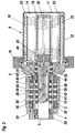
- a bioartificial device has a reactor vessel 6 which is one horizontal axis 13 is rotatably arranged in a base frame 1.
- a bearing block 2 is inserted vertically, in which a hollow cylindrical outer Drive shaft 4 is mounted, which has an end flange 5.
- the flange 5 and a housing pot connected to it via an easily detachable locking ring 16 11 made of a particularly transparent material form the reactor vessel 6.
- a central drive shaft 3 is rotatably mounted.
- Both drive shafts 3, 4 are with drive transmission elements 33, 34, for example Gears, pulleys or the like. Provided that a corresponding Traction means are connected to an output element 32 of a motor 31.
- the drive transmission element 34 preferably has a larger outside diameter, so that the speed of the drive shaft 4 is less than the speed of the drive shaft 3.
- the reactor vessel 6 has a cell culture chamber 14 which has at least one in Flange 5 formed test opening 15 is accessible. This can be used to take a sample the cell culture as well as a withdrawal or supply, in order to possibly Compensate for pressure changes in the reactor vessel 6. From the or a test opening 15 preferably a piece of pipe or tube 54 extends into the interior of the cell culture chamber 14 to take a sample from a non-marginal area enable.
- a flow chamber 17 for a nutrient medium leads through the cell culture chamber 14 and a flow chamber 21 for plasma or blood.
- the flow chambers 17 and 21 are arranged separately from one another and each formed by a hose 18, 22, that of a semipermeable material, in particular a polyvinylidene difluoride (PVDF), whose pore size corresponds to a maximum of about 100,000 daltons.
- PVDF polyvinylidene difluoride
- the flow chamber 17 for the nutrient medium is formed by the hose 18 which is wound helically on a carrier 19, which receives several of the turns Has carrier strips.
- the carrier 19 is on the end face of a connecting element 20 from which is attached to the central drive shaft 3. The carrier 19th and the hose 18 therefore rotate with the drive shaft 3.
- the hose 22, which forms the flow chamber 21 for plasma or blood is also two to eight Carrier strips wound helically, which form the carrier 23.
- the carrier strips of the carrier 23 are close to the peripheral wall 12 of the reactor vessel 6 from Flange 5, which on the preferably slower rotating outer drive shaft 4th is provided.
- Both tubes 18, 22 dip into the cell culture chamber 14, with the horizontal Axis of rotation 13 and the preferred speed difference between the two Hose coils have a slightly gentle stirring effect in the cell culture, through which the mass exchange between the nutrient medium in the central tube 18 and the cell culture and between the plasma or blood in the outer tube 22 and the cell culture is favored.
- the helical arrangement of the two hoses also results in a very large exchange area between the individual media.
- the Hose turns can touch each other (Fig. 1) or at a distance (Fig. 2) the carriers 19, 23 may be arranged.
- a touching arrangement results from a higher number of turns a greater total length while a spaced Arrangement allows the exchange on the entire circumference of the hose, since the mutual coverage in the contact area of the turns is eliminated.
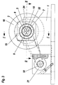
- connections 47, 48, 49, 50 are provided on bearing block 2, with radial bores 27, 28, 29, 30 of the central drive shaft 3 in Flow connection.
- outer ring channels 41 are provided for each inflow or return flow, which are delimited by axially spaced separating rings 42 and the respective flow connections between the connections 47, 48, 49, 50 and radial bores 37, 38, 39, 40 of the rotating outer drive shaft 4.
- the central drive shaft 3 contains four mutually parallel flow channels 7, 8, 9, 10. Of these, the flow channel 7 through a protruding into the housing pot 11 Extension tube 25 extends, the radially bent end with the Flange 5 opposite, first end of the hose 18 is connected.
- the Flow channel 8 is extended into a connecting element 20, and ends in a radial Inlet bore 24, to which the flange-near second end of the hose 18 is connected is. Nutrient medium for supplying the cell culture thus flows over the first connection 47 in the outer ring channel 41, through the bore 37 of the outer Drive shaft 4 in the inner ring channel 35, through the bore 27 of the central drive shaft 3 in the first flow channel 7 and through the extension tube 25 in the tube 18.
- the circulating nutrient medium flows through the Inlet opening 24, the second flow channel 8 and the radial bore 28 of the central drive shaft 3 in the associated inner ring channel 35, through the bore 38 of the outer drive shaft 4 and the associated outer ring channel 41 for second connection 48 of the bearing block 2.
- the flow channels 9, 10 of the central drive shaft 3 are via inner radial bores 43, 44 connected to ring channels 45 which are delimited by separating rings 46 and between the central drive shaft 3 and the flange 5 of the outer drive shaft 4 are arranged.
- the flange 5 has channels 51, 52 which extend into the area of the outer Carrier 23 lead.
- the hose 22 is connected at the outlet of the channel 51.
- An extension tube 53 leads from the exit of the channel 52 to the free end of the carrier 23 on which the second end of the hose 22 with the extension tube 53 is connected.
- Plasma or blood flows into the bioartificial device via the third connection 49 and passes through the associated outer ring channel 41 and the bore 39 of the outer drive shaft 4 in the associated inner ring channel 35, through the bore 29 of the central drive shaft 3 in its third flow channel 9, through the second, inner bore 43 at the end of the flow channel 9 in the associated ring channel 45 and through the channel 51 in the flange 5 to the outer hose coil 22, in the through Mass exchange with the cell culture in the cell culture chamber 14 a cleaning of the plasma or blood.
- the treated plasma or blood flows through the extension tube 53 and the channel 52 in the flange 5 in the associated ring channel 45, through the inner bore 44 of the central drive shaft 3 in its fourth flow channel 10, through the outer bore 30 of the central drive shaft 3 in the associated inner ring channel 35, and through the bore 40 of the outer drive shaft 4 and associated ring channel 41 to the fourth connection 50 of the bearing block 2.
- the bearing block 2 is removed from the base frame 1 removed so that the reactor vessel 6 can be set up, the axis 13th runs perpendicular.
- the bearing block 2 with the flange 5 and the hose coils arranged on the two supports 19, 23 18, 22 can be removed upwards.
- the used cell culture can be emptied or new cell culture can be filled into the housing pot 11.
- the unit out Flange 5 with the two hose coils 18, 22 and the bearing block 2 is on the housing pot 11 placed and with the help of the closure ring 16 to the reactor vessel 6 sealed.
- the reactor vessel 6 can then be folded over and can be inserted horizontally into the base frame 1 with the help of the bearing block 2.
- the housing pot 11 has a volume of approximately one cubic decimeter and can hold approximately 2 ⁇ 10 10 hepatocytes suspended in a medium.
- the speeds of the two drive cells 3, 4 are in particular between 20 and 40 revolutions per minute, the speed of the central drive shaft 3 corresponding, for example, to one and a quarter times the speed of the outer drive shaft 4. In this case, the speeds are from 20 and 30 revolutions to 25 and 37.5 revolutions per minute.
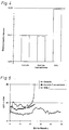
- Fig. 4 shows that the control animal and the plasmapheresis control animal have a survival time of almost 24 hours each.
- the third animal on the other hand, lived Plasma was cleaned or regenerated in the bioartificial device according to the invention, nearly 50 hours, with the cause of death, as shown in Fig. 5, not increasing intracranial pressure (ICP).
- ICP intracranial pressure
- the intracranial pressure increased extreme in the control animal and reduced in the plasmapheresis control animal, but clearly.
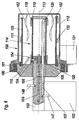
- a central cylindrical is in a bearing block 102 Holding element 103 arranged removably.
- the holding element has the connections shown 147, 148, via which nutrient medium can be supplied and removed, and two other connections through which blood and plasma can be supplied and removed.
- the Connections 147, 148 open into flow channels 107, 108, which are parallel to the axis 113 extend.
- On the holding element 103 is a flange 105 with a circumferential Rolling bearing 160 is mounted, on which a housing pot 111 of a reactor vessel 106 is rotatably mounted.
- the housing pot 111 is on the outside of the wall 112 provided with a ring gear 161, and with a drive transmission element Motor 131 rotatably connected.
- the flange 105 and the housing pot 111 of the reactor vessel 106 include a cell culture chamber 114 into which from the bottom of the housing pot 111 two stirring elements 162 protrude, which are caused by the rotation of the housing wall 112 conditioned, gentle mixing of the contents of the cell culture chamber 114 support.
- the flow channel 108 ends in a connecting element 120, which is a radial Bore 124 has.
- the flow channel 107 is beyond the connecting element 120 continued through an extension tube 125.
- One on ledges of a beam 119 helically wound hose 118 is on the one hand on the extension tube 125 and on the other hand connected to the radial bore 124, the Hose coil centrally in the extension of the holding element 103 in the rotating Housing pot 111 protrudes.
- a second on the slats of a carrier serves as the flow chamber for blood and plasma 123 helically wound hose 122, the one not shown in the flange 105 running channels are connected to flow channels in the holding element 103, of which the flow channel 109 is indicated by dashed lines.
- the reactor vessel 106 has a test opening 115 which is connected via an inner hose or tube piece 154 the cell culture chamber 114 is in communication.
Landscapes
- Health & Medical Sciences (AREA)
- Life Sciences & Earth Sciences (AREA)
- Engineering & Computer Science (AREA)
- Biomedical Technology (AREA)
- Organic Chemistry (AREA)
- Chemical & Material Sciences (AREA)
- Bioinformatics & Cheminformatics (AREA)
- Zoology (AREA)
- Wood Science & Technology (AREA)
- General Health & Medical Sciences (AREA)
- Genetics & Genomics (AREA)
- Heart & Thoracic Surgery (AREA)
- General Engineering & Computer Science (AREA)
- Biochemistry (AREA)
- Molecular Biology (AREA)
- Sustainable Development (AREA)
- Microbiology (AREA)
- Biotechnology (AREA)
- Public Health (AREA)
- Veterinary Medicine (AREA)
- Animal Behavior & Ethology (AREA)
- Cell Biology (AREA)
- Hematology (AREA)
- Anesthesiology (AREA)
- Vascular Medicine (AREA)
- Biodiversity & Conservation Biology (AREA)
- Clinical Laboratory Science (AREA)
- Medicinal Chemistry (AREA)
- General Chemical & Material Sciences (AREA)
- Chemical Kinetics & Catalysis (AREA)
- Pharmacology & Pharmacy (AREA)
- Gastroenterology & Hepatology (AREA)
- Nuclear Medicine, Radiotherapy & Molecular Imaging (AREA)
- Apparatus Associated With Microorganisms And Enzymes (AREA)
- Medicines Containing Material From Animals Or Micro-Organisms (AREA)
Priority Applications (5)
| Application Number | Priority Date | Filing Date | Title |
|---|---|---|---|
| EP01103420A EP1234553A1 (fr) | 2001-02-14 | 2001-02-14 | Dispositif bioartificiel |
| PCT/AT2002/000045 WO2002064063A1 (fr) | 2001-02-14 | 2002-02-11 | Appareil bioartificiel pour le stockage, la culture et/ou la reproduction de cellules |
| EP02710668A EP1363557A1 (fr) | 2001-02-14 | 2002-02-11 | Appareil bioartificiel pour le stockage, la culture et/ou la reproduction de cellules |
| JP2002563863A JP2004526438A (ja) | 2001-02-14 | 2002-02-11 | 細胞の貯蔵・培養および/または増殖のための人工バイオ装置 |
| US10/641,275 US7067307B2 (en) | 2001-02-14 | 2003-08-14 | Bioartificial device for the storage, cultivation and/or multiplication of cells |
Applications Claiming Priority (1)
| Application Number | Priority Date | Filing Date | Title |
|---|---|---|---|
| EP01103420A EP1234553A1 (fr) | 2001-02-14 | 2001-02-14 | Dispositif bioartificiel |
Publications (1)
| Publication Number | Publication Date |
|---|---|
| EP1234553A1 true EP1234553A1 (fr) | 2002-08-28 |
Family
ID=8176483
Family Applications (2)
| Application Number | Title | Priority Date | Filing Date |
|---|---|---|---|
| EP01103420A Withdrawn EP1234553A1 (fr) | 2001-02-14 | 2001-02-14 | Dispositif bioartificiel |
| EP02710668A Withdrawn EP1363557A1 (fr) | 2001-02-14 | 2002-02-11 | Appareil bioartificiel pour le stockage, la culture et/ou la reproduction de cellules |
Family Applications After (1)
| Application Number | Title | Priority Date | Filing Date |
|---|---|---|---|
| EP02710668A Withdrawn EP1363557A1 (fr) | 2001-02-14 | 2002-02-11 | Appareil bioartificiel pour le stockage, la culture et/ou la reproduction de cellules |
Country Status (4)
| Country | Link |
|---|---|
| US (1) | US7067307B2 (fr) |
| EP (2) | EP1234553A1 (fr) |
| JP (1) | JP2004526438A (fr) |
| WO (1) | WO2002064063A1 (fr) |
Families Citing this family (16)
| Publication number | Priority date | Publication date | Assignee | Title |
|---|---|---|---|---|
| WO2006127490A1 (fr) * | 2005-05-20 | 2006-11-30 | University Of Dayton | Ensemble gaine de colonne elastique pour chromatographie en phase gazeuse |
| GB2450761B (en) * | 2007-07-06 | 2010-08-04 | Univ London | Multi-functional chamber for housing a biological component |
| RU2013127313A (ru) | 2010-11-16 | 2014-12-27 | Те Борд Оф Трастиз Оф Те Лилэнд Стэнфорд Джуниор Юниверсити | Системы и способы лечения сухого глаза |
| US9821159B2 (en) | 2010-11-16 | 2017-11-21 | The Board Of Trustees Of The Leland Stanford Junior University | Stimulation devices and methods |
| WO2014138709A1 (fr) | 2013-03-08 | 2014-09-12 | Oculeve, Inc. | Dispositifs et procédés pour traiter un œil sec chez des animaux |
| EP2967817B1 (fr) | 2013-03-12 | 2021-03-10 | Oculeve, Inc. | Dispositifs et systèmes de pose d'implant |
| EP2986339A4 (fr) | 2013-04-19 | 2016-12-21 | Oculeve Inc | Dispositifs et procédés de stimulation nasale |
| US9770583B2 (en) | 2014-02-25 | 2017-09-26 | Oculeve, Inc. | Polymer formulations for nasolacrimal stimulation |
| US9687652B2 (en) | 2014-07-25 | 2017-06-27 | Oculeve, Inc. | Stimulation patterns for treating dry eye |
| AU2015335772B2 (en) | 2014-10-22 | 2020-07-09 | Oculeve, Inc. | Contact lens for increasing tear production |
| EP3209371A4 (fr) | 2014-10-22 | 2018-10-24 | Oculeve, Inc. | Systèmes et procédés de stimulateur nasal implantable |
| EP3721938A1 (fr) | 2014-10-22 | 2020-10-14 | Oculeve, Inc. | Dispositifs de stimulation et procédés pour le traitement de la sécheresse oculaire |
| US10426958B2 (en) | 2015-12-04 | 2019-10-01 | Oculeve, Inc. | Intranasal stimulation for enhanced release of ocular mucins and other tear proteins |
| US10252048B2 (en) | 2016-02-19 | 2019-04-09 | Oculeve, Inc. | Nasal stimulation for rhinitis, nasal congestion, and ocular allergies |
| AU2017260237A1 (en) | 2016-05-02 | 2018-11-22 | Oculeve, Inc. | Intranasal stimulation for treatment of meibomian gland disease and blepharitis |
| EP3547898A4 (fr) | 2016-12-02 | 2020-07-08 | Oculeve, Inc. | Appareil et méthode de prévision de sécheresse oculaire et recommandation de traitement |
Citations (5)
| Publication number | Priority date | Publication date | Assignee | Title |
|---|---|---|---|---|
| US4242459A (en) * | 1978-11-02 | 1980-12-30 | Chick William L | Cell culture device |
| US4242460A (en) * | 1978-12-26 | 1980-12-30 | Chick William L | Cell culture device |
| US4323457A (en) * | 1977-03-21 | 1982-04-06 | Connaught Laboratories Limited | Artificial endocrine pancreas |
| US4649114A (en) * | 1979-10-05 | 1987-03-10 | Intermedicat Gmbh | Oxygen permeable membrane in fermenter for oxygen enrichment of broth |
| US5043260A (en) * | 1987-11-02 | 1991-08-27 | Rhode Island Hospital | Perfusion device with hepatocytes |
Family Cites Families (9)
| Publication number | Priority date | Publication date | Assignee | Title |
|---|---|---|---|---|
| US3734851A (en) * | 1969-12-29 | 1973-05-22 | K Matsumura | Method and device for purifying blood |
| US4808378A (en) * | 1985-11-11 | 1989-02-28 | Senko Medical Instrument Mfg. Co., Ltd. | Blood oxygenator |
| US5081035A (en) * | 1988-04-18 | 1992-01-14 | The University Of Michigan | Bioreactor system |
| US5605835A (en) | 1988-05-23 | 1997-02-25 | Regents Of The University Of Minnesota | Bioreactor device with application as a bioartificial liver |
| US4988623A (en) * | 1988-06-30 | 1991-01-29 | The United States Of America As Represented By The Administrator Of The National Aeronautics And Space Administration | Rotating bio-reactor cell culture apparatus |
| US5026650A (en) * | 1988-06-30 | 1991-06-25 | The United States Of Amercia As Represented By The Administrator Of The National Aeronautics And Space Administration | Horizontally rotated cell culture system with a coaxial tubular oxygenator |
| FR2640638B1 (fr) * | 1988-12-20 | 1991-02-15 | Commissariat Energie Atomique | Bioreacteur et dispositif pour la culture de cellules animales |
| US5712154A (en) * | 1995-06-07 | 1998-01-27 | W.R. Grace & Co.-Conn. | Dual fiber bioreactor |
| US5827729A (en) | 1996-04-23 | 1998-10-27 | Advanced Tissue Sciences | Diffusion gradient bioreactor and extracorporeal liver device using a three-dimensional liver tissue |
-
2001
- 2001-02-14 EP EP01103420A patent/EP1234553A1/fr not_active Withdrawn
-
2002
- 2002-02-11 EP EP02710668A patent/EP1363557A1/fr not_active Withdrawn
- 2002-02-11 JP JP2002563863A patent/JP2004526438A/ja active Pending
- 2002-02-11 WO PCT/AT2002/000045 patent/WO2002064063A1/fr not_active Ceased
-
2003
- 2003-08-14 US US10/641,275 patent/US7067307B2/en not_active Expired - Fee Related
Patent Citations (5)
| Publication number | Priority date | Publication date | Assignee | Title |
|---|---|---|---|---|
| US4323457A (en) * | 1977-03-21 | 1982-04-06 | Connaught Laboratories Limited | Artificial endocrine pancreas |
| US4242459A (en) * | 1978-11-02 | 1980-12-30 | Chick William L | Cell culture device |
| US4242460A (en) * | 1978-12-26 | 1980-12-30 | Chick William L | Cell culture device |
| US4649114A (en) * | 1979-10-05 | 1987-03-10 | Intermedicat Gmbh | Oxygen permeable membrane in fermenter for oxygen enrichment of broth |
| US5043260A (en) * | 1987-11-02 | 1991-08-27 | Rhode Island Hospital | Perfusion device with hepatocytes |
Non-Patent Citations (1)
| Title |
|---|
| "CONTROLLED-TURBULENCE BIOREACTORS", NTIS TECH NOTES,US,US DEPARTMENT OF COMMERCE. SPRINGFIELD, VA, 1 March 1990 (1990-03-01), pages 294, XP000127294, ISSN: 0889-8464 * |
Also Published As
| Publication number | Publication date |
|---|---|
| WO2002064063A1 (fr) | 2002-08-22 |
| US7067307B2 (en) | 2006-06-27 |
| EP1363557A1 (fr) | 2003-11-26 |
| US20040033593A1 (en) | 2004-02-19 |
| JP2004526438A (ja) | 2004-09-02 |
Similar Documents
| Publication | Publication Date | Title |
|---|---|---|
| EP1234553A1 (fr) | Dispositif bioartificiel | |
| DE69810740T2 (de) | Bioreaktor | |
| DE2734248A1 (de) | Tragbare kuenstliche niere | |
| DE60030885T2 (de) | Filterkartusche für sterile flüssigkeit und verfahren zu dessen verwendung | |
| DE69330179T2 (de) | Membran und Verfahren für die Trennung von proteingebundenen Substanzen aus einer Protein enthaltenden Flüssigkeit mittels Dialyse | |
| DE69117750T2 (de) | Vorrichtung zum herstellen von koagulationsfaktorkonzentraten, wie fibrinogen, aus blutproben | |
| DE2715821C2 (de) | Verfahren zur in vitro-Zellkultur und Zellkultur-Reaktionsgefäß zur Durchführung dieses Verfahrens | |
| DE3035118C2 (de) | Verfahren zur Kultivierung von schwimmenden Tierzellen und Vorrichtung zur Durchführung des Verfahrens | |
| DE2624373C2 (de) | Verfahren zur Herstellung von steril filtriertem Kryopräzipilat mit einer Anreicherung des Faktors VIII | |
| DE2711995A1 (de) | Trennvorrichtung, insbesondere vorrichtung zur haemodialyse | |
| DE2430171A1 (de) | Dialysiervorrichtung mit selektiver chemischer aktivitaet | |
| DE3101159A1 (de) | Verfahren und vorrichtung zur reinigung von blut | |
| CH624712A5 (fr) | ||
| DE2640451A1 (de) | Verfahren und vorrichtung zur zuechtung, haltung und befoerderung lebender organismen | |
| EP1083984B1 (fr) | Technique permettant d'ensemencer des substrats a plusieurs couches avec des cellules biologiques et dispositifs d'ensemencement associes | |
| DE2518108A1 (de) | Kuenstliche niere | |
| WO2005121311A1 (fr) | Reacteur d'exposition a une phase liquide-gazeuse pour la culture de cellules | |
| DE60220790T2 (de) | Vorrichtung zur änderung einer Flüssigkeit mittels einer selektivdurchlässige Membran | |
| DE1960505A1 (de) | Vorrichtung zur Reinigung von Blut | |
| DE2025420C3 (de) | Dialysierkolonne | |
| DE3222244A1 (de) | Verfahren und vorrichtung zum behandeln von menschlichem blut | |
| DE69106726T2 (de) | Vorrichtung zum entwickeln einer rotierenden austauschfläche. | |
| DE2701976A1 (de) | Blutwaschzentrifuge | |
| DE69314590T2 (de) | Behandlung von Proteinhaltigen Körperflüssigkeiten | |
| DE2444583A1 (de) | Dialyse-geraet mit adsorber-einheit |
Legal Events
| Date | Code | Title | Description |
|---|---|---|---|
| PUAI | Public reference made under article 153(3) epc to a published international application that has entered the european phase |
Free format text: ORIGINAL CODE: 0009012 |
|
| AK | Designated contracting states |
Kind code of ref document: A1 Designated state(s): AT BE CH CY DE DK ES FI FR GB GR IE IT LI LU MC NL PT SE TR |
|
| AX | Request for extension of the european patent |
Free format text: AL;LT;LV;MK;RO;SI |
|
| AKX | Designation fees paid | ||
| REG | Reference to a national code |
Ref country code: DE Ref legal event code: 8566 |
|
| STAA | Information on the status of an ep patent application or granted ep patent |
Free format text: STATUS: THE APPLICATION IS DEEMED TO BE WITHDRAWN |
|
| 18D | Application deemed to be withdrawn |
Effective date: 20030301 |