EP1234561A2 - Verfahren zur Formgebung von Oberflächen, insbesondere von Linsen - Google Patents
Verfahren zur Formgebung von Oberflächen, insbesondere von Linsen Download PDFInfo
- Publication number
- EP1234561A2 EP1234561A2 EP02007539A EP02007539A EP1234561A2 EP 1234561 A2 EP1234561 A2 EP 1234561A2 EP 02007539 A EP02007539 A EP 02007539A EP 02007539 A EP02007539 A EP 02007539A EP 1234561 A2 EP1234561 A2 EP 1234561A2
- Authority
- EP
- European Patent Office
- Prior art keywords
- laser
- area
- ablation
- unit
- individual
- Prior art date
- Legal status (The legal status is an assumption and is not a legal conclusion. Google has not performed a legal analysis and makes no representation as to the accuracy of the status listed.)
- Withdrawn
Links
Images


Classifications
-
- B—PERFORMING OPERATIONS; TRANSPORTING
- B23—MACHINE TOOLS; METAL-WORKING NOT OTHERWISE PROVIDED FOR
- B23K—SOLDERING OR UNSOLDERING; WELDING; CLADDING OR PLATING BY SOLDERING OR WELDING; CUTTING BY APPLYING HEAT LOCALLY, e.g. FLAME CUTTING; WORKING BY LASER BEAM
- B23K26/00—Working by laser beam, e.g. welding, cutting or boring
- B23K26/02—Positioning or observing the workpiece, e.g. with respect to the point of impact; Aligning, aiming or focusing the laser beam
- B23K26/06—Shaping the laser beam, e.g. by masks or multi-focusing
-
- A—HUMAN NECESSITIES
- A61—MEDICAL OR VETERINARY SCIENCE; HYGIENE
- A61F—FILTERS IMPLANTABLE INTO BLOOD VESSELS; PROSTHESES; DEVICES PROVIDING PATENCY TO, OR PREVENTING COLLAPSING OF, TUBULAR STRUCTURES OF THE BODY, e.g. STENTS; ORTHOPAEDIC, NURSING OR CONTRACEPTIVE DEVICES; FOMENTATION; TREATMENT OR PROTECTION OF EYES OR EARS; BANDAGES, DRESSINGS OR ABSORBENT PADS; FIRST-AID KITS
- A61F9/00—Methods or devices for treatment of the eyes; Devices for putting in contact-lenses; Devices to correct squinting; Apparatus to guide the blind; Protective devices for the eyes, carried on the body or in the hand
- A61F9/007—Methods or devices for eye surgery
- A61F9/008—Methods or devices for eye surgery using laser
- A61F9/00802—Methods or devices for eye surgery using laser for photoablation
- A61F9/00812—Inlays; Onlays; Intraocular lenses [IOL]
-
- B—PERFORMING OPERATIONS; TRANSPORTING
- B23—MACHINE TOOLS; METAL-WORKING NOT OTHERWISE PROVIDED FOR
- B23K—SOLDERING OR UNSOLDERING; WELDING; CLADDING OR PLATING BY SOLDERING OR WELDING; CUTTING BY APPLYING HEAT LOCALLY, e.g. FLAME CUTTING; WORKING BY LASER BEAM
- B23K26/00—Working by laser beam, e.g. welding, cutting or boring
- B23K26/02—Positioning or observing the workpiece, e.g. with respect to the point of impact; Aligning, aiming or focusing the laser beam
- B23K26/06—Shaping the laser beam, e.g. by masks or multi-focusing
- B23K26/064—Shaping the laser beam, e.g. by masks or multi-focusing by means of optical elements, e.g. lenses, mirrors or prisms
-
- A—HUMAN NECESSITIES
- A61—MEDICAL OR VETERINARY SCIENCE; HYGIENE
- A61F—FILTERS IMPLANTABLE INTO BLOOD VESSELS; PROSTHESES; DEVICES PROVIDING PATENCY TO, OR PREVENTING COLLAPSING OF, TUBULAR STRUCTURES OF THE BODY, e.g. STENTS; ORTHOPAEDIC, NURSING OR CONTRACEPTIVE DEVICES; FOMENTATION; TREATMENT OR PROTECTION OF EYES OR EARS; BANDAGES, DRESSINGS OR ABSORBENT PADS; FIRST-AID KITS
- A61F9/00—Methods or devices for treatment of the eyes; Devices for putting in contact-lenses; Devices to correct squinting; Apparatus to guide the blind; Protective devices for the eyes, carried on the body or in the hand
- A61F9/007—Methods or devices for eye surgery
- A61F9/008—Methods or devices for eye surgery using laser
- A61F2009/00861—Methods or devices for eye surgery using laser adapted for treatment at a particular location
- A61F2009/00872—Cornea
-
- A—HUMAN NECESSITIES
- A61—MEDICAL OR VETERINARY SCIENCE; HYGIENE
- A61F—FILTERS IMPLANTABLE INTO BLOOD VESSELS; PROSTHESES; DEVICES PROVIDING PATENCY TO, OR PREVENTING COLLAPSING OF, TUBULAR STRUCTURES OF THE BODY, e.g. STENTS; ORTHOPAEDIC, NURSING OR CONTRACEPTIVE DEVICES; FOMENTATION; TREATMENT OR PROTECTION OF EYES OR EARS; BANDAGES, DRESSINGS OR ABSORBENT PADS; FIRST-AID KITS
- A61F9/00—Methods or devices for treatment of the eyes; Devices for putting in contact-lenses; Devices to correct squinting; Apparatus to guide the blind; Protective devices for the eyes, carried on the body or in the hand
- A61F9/007—Methods or devices for eye surgery
- A61F9/008—Methods or devices for eye surgery using laser
- A61F2009/00897—Scanning mechanisms or algorithms
-
- B—PERFORMING OPERATIONS; TRANSPORTING
- B23—MACHINE TOOLS; METAL-WORKING NOT OTHERWISE PROVIDED FOR
- B23K—SOLDERING OR UNSOLDERING; WELDING; CLADDING OR PLATING BY SOLDERING OR WELDING; CUTTING BY APPLYING HEAT LOCALLY, e.g. FLAME CUTTING; WORKING BY LASER BEAM
- B23K2103/00—Materials to be soldered, welded or cut
- B23K2103/30—Organic materials
-
- B—PERFORMING OPERATIONS; TRANSPORTING
- B23—MACHINE TOOLS; METAL-WORKING NOT OTHERWISE PROVIDED FOR
- B23K—SOLDERING OR UNSOLDERING; WELDING; CLADDING OR PLATING BY SOLDERING OR WELDING; CUTTING BY APPLYING HEAT LOCALLY, e.g. FLAME CUTTING; WORKING BY LASER BEAM
- B23K2103/00—Materials to be soldered, welded or cut
- B23K2103/50—Inorganic materials other than metals or composite materials
Definitions
- the invention relates to a method for shaping surfaces, in particular of lenses, by means of laser ablation of the Surfaces, especially, but not exclusively, of surfaces biological materials.
- the invention is preferably used in Photo Refractive Keratectomy (PRK) and ophthalmological exact formation of contact lenses.
- PRK Photo Refractive Keratectomy
- the known state of the art will be described below with reference to that closest to the invention, which deals with the correction of ametropia.
- the ablative procedures for the treatment of ametropia in the human eye which have been carried out since the mid-1980s, are all based on the formulas described by Munnerlin for the first time for calculating the necessary flattening or division of the cornea. If myopia is corrected, more corneal tissue is removed in the corneal center than in the peripheral area of the cornea according to these calculations. If farsightedness is corrected, more tissue is removed in the corneal periphery than in the center of the cornea. The resulting strengthening or weakening effect on the refractive power of the cornea surface corresponds in its effect to that of a contact lens.
- the corresponding amount of cornea is removed from all known methods, close to the invention, in individual, successive areas of constantly changing areas.
- these areas are continuously smaller with successive circles or increasing diameters.
- 5,520,679 describes an ophthalmological surgical method using a spot scanning laser in which the cornea is removed by setting individual laser spots.
- this method which is carried out in the same way as the ablation methods mentioned above, an attempt is made to achieve a surface that is as uniform as possible in the area by setting immediately successive laser spots with a defined overlap ratio.
- this requires, especially when using an erbium laser, an increased thermal load on individual surface areas.
- a similar process is described in WO 96/11655.
- shot positions are arranged on rings with a certain radius according to an empirical algorithm.
- a large number of relatively overlapping shots are provided on each ring.
- the firing order is therefore so determined according to WO 96/11655 that successive shots do not overlap.
- the shots are sorted so that the respective distance between them is maximum.
- it is proposed to randomly rearrange the field of fire so that the number of overlapping shots is statistically reduced.
- WO 96/11655 The only criterion for the random setting of the individual shots according to WO 96/11655 is thus the avoidance of local overheating.
- the individual spots set according to WO 96/11655 which are placed on predetermined tracks (rings) in such a way that individual spots of a laser beam with a large diameter overlap, a complete partial correction cannot be achieved.
- myopia is started with the smallest ring and the diameter of the ablation area is then continuously increased. If there is an interruption (e.g. power failure), only the center has been processed, whereby an undefined state, an optical chaos, which may have led to a deterioration in the initial state, has been reached. The same applies to hyperopia, where the removal process takes place continuously from the outside.
- EP 0 247 260 A2 describes a method and a device for Radial keratotomy described. At radial keratotomy incisions made on the cornea; the flattening of the cornea results indirectly from the limbus-parallel dehiscence of the radial oriented wound edges. EP 0 247 260 A2 has the task in making the effects of these surgeries more predictable do. For this purpose there will be an experience database built up in which the values before and after a complete performed operation as well as those performed for this operation medical measures are saved. Furthermore, in this Scripture stated that even with the photorefractive keratotomy Predictability of a complete treatment outcome performed surgery is not sufficient, so that too the creation of an analogue experience database is proposed.
- EP 0 247 260 A2 the final state of various operations that are far apart in time and the final result compared with the respective initial state.
- Experience database specified for EP 0 247 260 A2 (for one inexperienced surgeon) is not one who is active within a uniform Ablation process can be used or could be used for this.
- the invention has for its object to provide a method for shaping surfaces, in particular lenses and in particular surfaces of biological materials using a laser with a pulsed laser output beam, which ensure that in the event of a sudden deliberate or unwanted surface treatment abort at least an acceptable partial correction of the machining surface is present, which represents an improvement in the conditions of the initial state. Furthermore, it is an object of the invention to largely reduce the thermal load on the surface to be machined, in particular when using an erbium laser. The object is achieved by the characterizing features of patent claim 1. Advantageous further developments are covered in the subordinate claims.
- the individual layers a surface to be machined in a predetermined order worn away to reduce the risk of vision deterioration to minimize unforeseen treatment discontinuations.
- spherical at the end Corneal surface with the entire desired correction are as many partial corrections as possible in the proposed method generated with acceptable intermediate results.
- Treatment discontinuation is therefore never very irregular machined surfaces.
- the full, achieved by editing the desired correction but the Remaining visual defects can be much easier with glasses or Contact lens can be fixed. It can also be used later Time of a new PRK much easier, even with after other methods working devices.
- the shaping process described is currently suitable for everyone used PRK methods such as area ablation, slit scanning and small Spot scanning, both for ablation on the corneal surface and also intrastromal tissue ablation in connection with the LASIK method or picosecond lasers.
- the proposed procedure differs from that of the Area ablation principle working equipment used occasionally Multi pass method in that there are deliberately many, if possible small partial corrections are generated. With the Multi Pass typically only a division into 2 - 3 partial corrections. Moreover The Multi Pass technique is primarily used for certain purposes the area ablation typical side effects, such as one too strong Dehydration, excessive tissue warming and development from Central Islands.
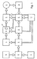
- Figure 1 are the essential components in block diagram form shown in the procedure. First is one in itself Known pulsed laser 1 used for laser scanning is provided.
- lasers with a pulsed laser output beam for example UV lasers such as Eximer lasers, Er: YAG lasers or Q-switched lasers, are suitable for the intended use of suitable wavelength and intensity or energy.
- a beam shaping unit 2 Downstream of the laser 1 is a beam shaping unit 2, which, as is known from the prior art, is formed from lenses, mirrors and prisms.
- a laser beam deflection unit 3 which is coordinated with the laser pulse sequence, is provided, which deflects the laser radiation onto the surface 4 to be processed in a defined manner.
- the laser beam deflection unit 3 and the beam shaping unit 2 are connected to a control unit 5.
- a first input unit 6 receives the refractive input variables (eg dpt, sph, cyl) of the surface 4 to be processed. These output parameters are initially to be determined in the usual way, regardless of the processing device.
- a second input unit 7 is provided, which is used primarily for recording laser-relevant data. Such data relate to the laser beam diameter, the energy density of the laser beam and the energy distribution over the laser beam cross section and an overlap factor, which can be variably specified individually as well as in its entirety.
- a calculation unit 8 is assigned to these two input units 6, 7, within which all necessary individual laser shot coordinates are assigned to one another depending on the total surface 4 to be removed.
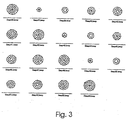
- the calculation unit 8 is followed by a so-called block generator 9, to which the data from the calculation unit 8 are fed, and in which the individual laser shot coordinates for the removal of an individual surface layer to be removed, which can be specified as desired (see, for example, FIG. 3, any area captured by a step x).
- the block generator 9 is followed by a sequence generator 10, in which the individual blocks formed in the block generator 9 are combined and brought into a sequence on which the invention is based.
- This sequence represents a block sequence which, based on FIG. 3, shows the processing sub-steps (Step1 to 6; 7-12; 13-18; 19-24; 25-30; 31-36; 37-42; 43-48; 49 -54).
- Each of these processing sub-steps represents a complete partial correction in itself.
- the defined block sequence sent from the sequence generator 10 to the control unit 5 through the interaction of previously mentioned units serves on the one hand to control the laser beam deflection unit 3 and on the other hand to control the beam shaping unit 2 and there in particular to control it an aperture 21 provided in the beam shaping unit 2 and whose opening can be changed, the function of which is explained in more detail when the method is run.
- a central computer unit 11 is provided which, depending on the control data leaving the control unit 5, connects and controls at least the laser unit 1, the beam shaping unit 2; 21 and the laser beam deflection unit 3 are coordinated in a predeterminable manner.
- the first and second input unit 6; 7, the calculation unit 8, the block generator 9, the sequence generator 10 and the control unit 5 are assigned to a second computer unit connected to the central computer 11. It is also possible to integrate the units mentioned in the central computer 11.
- a monitoring unit 12 is advantageously provided, which detects random deflection movements of the surface 4 to be processed and forwards corresponding correction signals to the laser beam deflection unit 3 via the control unit 5.
- Such a monitoring unit is described, for example, by A. Unkroth et al. in "Corneal surgery by two-dimensionally scanning of a low-energy excimer laser beam” SPIE Vol. 2126 Ophthalmic Technol. IV 1994 pp. 217ff. described.
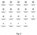
- Figure 2 which exemplifies the sequence required Processing steps for a myopia correction in the case of application the so-called small spot scanning according to the state of the art represents are explained.
- Figure 2 are the individual Ablation layers arranged in continuous rows, as in a Treatment of spherical myopia in small spot scanning would be used.
- the individual points mark the center points of the individual laser ablation of a circular laser beam with approximately 1-2 mm diameter.
- suitable overlap factor and suitable e.g. Gaussian beam profile results from all of the individual laser shots per layer with respect to those to be generated Correction of some kind, but more refractive evenly Tissue removal within an area.
- the area ablation method such an area would correspond to a single laser pulse.
- Step1 a first step
- Step2 four laser spots in succession corresponding to the Requirement a) are set. So that means after setting each current laser spots are preferably only set in each case laser spots further away from him, causing local overheating, due to the placement of several spots in a small area, effective is prevented. Preference is given only to the following ones Removal layers (Step2, ..., n) a partial overlap of previous ones Removal areas approved by the control unit 5.
- Step2 several laser spots set in a slightly enlarged area, being the four laser spots set in the middle in accordance with Step1 in the example Step2 is already offset to the one after Step1.
- Step1 If you look at furthermore only the laser spots set in the middle area after Step1 (see steps 3 to 6), it can be seen that in the following also the number the laser spots and their coordinates are changed. The same goes for also for the other areas surrounding the central area.
- the generated first sequence (steps 1 to 6) of removal steps then results already a first optical partial correction, in accordance with the requirement d1) possibly a necessary termination of the molding process without adverse effects could occur. If you consider this in Fig. 3 exemplary method up to the last processing step in the individual block sequences, it can be seen that a constant change in the number and coordinates of each Laser spots result in a uniform material removal, with an in higher ablation in the central areas, because there are laser spots with every step be set, is achieved. With appropriate procedures can thus an exact spherical lens correction was carried out in the example become.
- the shaping method with variation of the laser spot diameter and / or the laser beam energy density and / or the laser spot profile during the execution of the method steps according to the requirements a) to c) by a corresponding control of the laser 1 and / or the beam shaping unit 2 is first carried out at least once with first parameters, after which the method steps according to a) to c) are repeated repeatedly with changed parameters until a processing state corresponding to a partial correction according to the provision d1) or a complete correction according to the provision d2) is achieved becomes. It is particularly within the scope of the invention to use laser spots with different spot diameters.
- At least one machining cycle a) to c) is advantageously carried out with a large laser spot diameter and others with smaller laser spot diameters.
- the combination of machining cycles with different laser spot diameters ensures both the realization of short machining times and a shaping removal in accordance with the desired parameters. If, for example, a laser beam with a diameter of 1 mm is used during the fine removal, at least in areas in which a larger removal is required, at least once a shaping removal in accordance with the requirements of a) to c) with a larger laser beam diameter , for example with 2 mm.
- the shortening of the Processing time while backing up the desired one Realize removal in that between laser 1 and processing surface 4 a the energy density of the laser radiation influencing element is arranged.
- Such an element can e.g. be a mechanical or variable optical attenuator. Also lies it within the scope of the invention at least one processing cycle a) to c) with high energy density and others with low energy density perform.
- the invention is not based on the exemplary embodiments described limited. So it is e.g. also within the scope of the invention that individual Ablation areas by means of the beam shaping unit 2; 21 and / or the laser beam deflection unit 3 by self-contained ring tracks or column-like ablation zones are formed, which is characterized by the removal method according to the invention basically any, from Spherical target value have different lens corrections made.
- the lasers proposed for the PRK or the LASIK method come into consideration.
- the laser is preferably an excimer laser with a wavelength of 193 nm or an Er: YAG laser with a wavelength of 2940 nm.
- the energy density applied to the surface to be processed is preferably 100-300 mJ / cm 2 in an embodiment according to the invention.
- the laser spot on the surface 4 to be machined is largely circular and has a laser spot diameter of 3 mm for at least one ablation layer. Additional layers are removed with a laser spot diameter of 1 mm.
- the beam profile can in particular have a Gaussian distribution here, but a pot-shaped distribution is also possible.
Landscapes
- Health & Medical Sciences (AREA)
- Optics & Photonics (AREA)
- Physics & Mathematics (AREA)
- Engineering & Computer Science (AREA)
- Ophthalmology & Optometry (AREA)
- Surgery (AREA)
- Life Sciences & Earth Sciences (AREA)
- Mechanical Engineering (AREA)
- Plasma & Fusion (AREA)
- Biomedical Technology (AREA)
- Heart & Thoracic Surgery (AREA)
- Vascular Medicine (AREA)
- Nuclear Medicine, Radiotherapy & Molecular Imaging (AREA)
- Animal Behavior & Ethology (AREA)
- General Health & Medical Sciences (AREA)
- Public Health (AREA)
- Veterinary Medicine (AREA)
- Laser Beam Processing (AREA)
- Laser Surgery Devices (AREA)
Abstract
Description
Die seit Mitte der 80er Jahre durchgeführten ablativen Verfahren zur Behandlung von Fehlsichtigkeiten am menschlichen Auge beruhen alle auf den erstmalig von Munnerlin beschriebenen Formeln für die Berechnung der nötigen Abflachung bzw. Aufsteilung der Hornhaut. Im Falle der Korrektur einer Kurzsichtigkeit wird gemäß dieser Berechnungen mehr Hornhautgewebe im Hornhautzentrum als im peripheren Bereich der Hornhaut entfernt. Im Falle der Korrektur von Weitsichtigkeit wird mehr Gewebe in der Hornhautperipherie als im Zentrum der Hornhaut abgetragen. Der dadurch auf die Brechkraft der Hornhautoberfläche entstehende verstärkende oder abschwächende Effekt entspricht in seiner Wirkung dem einer Kontaktlinse.
Eine umfassende Beschreibung des bislang bekannten Standes der Technik ist in EP 90 308 709.6 (entspricht DE 690 24 558 T2) abgehandelt.
In US-PS 5,520,679 ist eine ophthalmologische Operationsmethode unter Verwendung eines Spot Scanning Lasers beschrieben, bei der der Hornhautabtrag durch Setzen einzelner Laserspots erfolgt. Bei diesem Verfahren, das im übrigen wie die o.g. Abtragverfahren durchgeführt wird, wird versucht, einen flächenmäßig möglichst gleichmäßigen Abtrag dadurch zu erzielen, daß zeitlich unmittelbar aufeinanderfolgende Laserspots mit einem definierten Überlappungsverhältnis gesetzt werden. Dies bedingt jedoch, insbesondere bei Einsatz eines Erbium-Lasers eine erhöhte thermische Belastung einzelner Flächenareale.
Entsprechend der nach WO 96/11655 gesetzten Einzelspots, die auf vorgegebenen Bahnen (rings) derart gesetzt werden, daß sich Einzelspots eines Laserstrahls mit großem Durchmesser überlappen, ist eine vollständige Teilkorrektur nicht erreichbar. Nach WO 96/11655 wird bei der Myopie mit dem kleinsten Ring gestartet und der Durchmesser des Abtraggebietes anschließend kontinuierlich erhöht. Sollte es hierbei zu einem Abbruch (bspw. Stromausfall) kommen, ist nur das Zentrum bearbeitet, wobei ein unbestimmter Zustand, ein optisches Chaos, der u.U. zu einer Verschlechterung des Ausgangszustandes geführt haben kann, erreicht wurde. Gleiches trifft bei der Hyperopie zu, wo der Abtragprozeß kontinuierlich von außen beginnend erfolgt.
Die Aufgabe wird durch die kennzeichnenden Merkmale von Patentanspruch 1 gelöst. Vorteilhafte weitere Ausgestaltungen sind in den nachgeordneten Ansprüchen erfaßt.
- Fig. 1
- blockschaltbildartig die wesentlichen beim Verfahren zum Einsatz gelangenden Komponenten sowie ihre funktionelle Zuordnung zueinander,
- Fig. 2
- beispielhaft die Abfolge erforderlicher Bearbeitungsschritte für eine Myopie Korrektur im Falle der Anwendung des sogenannten Small Spot Scanning nach dem Stand der Technik und
- Fig. 3
- eine Möglichkeit der erfindungsgemäßen Abfolge erforderlicher Bearbeitungsschritte für eine Myopie Korrektur ebenfalls im Falle der Anwendung des Small Spot Scanning.
Es liegt im Rahmen der Erfindung, die erste und zweite Eingabeeinheit 6; 7, die Berechnungseinheit 8, den Blockgenerator 9, den Ablaufgenerator 10 und die Ansteuereinheit 5 einer zweiten, mit dem Zentralrechner 11 in Verbindung stehenden Rechnereinheit zuzuordnen. Auch ist es möglich, die genannten Einheiten im Zentralrechner 11 zu integrieren.
Zusätzlich zu den bis hierher beschriebenen Einheiten ist vorteilhaft eine Überwachungseinheit 12 vorgesehen, die zufällige Auslenkbewegungen der zu bearbeitenden Oberfläche 4 erfaßt und über die Ansteuereinheit 5 entsprechende Korrektursignale an die Laserstrahlablenkeinheit 3 weiterleitet. Eine solche Überwachungseinheit ist z.B. von A. Unkroth et al. in "Corneal surgery by two-dimensionally scanning of a low-energy excimer laser beam" SPIE Vol. 2126 Ophthalmic Technol. IV 1994 S. 217ff. beschrieben.
Als sinnvoll erscheint eine Mindestzahl von 5 Schichten und eine bestimmbare Höchstzahl, die einer Korrektur von annähernd einer halben Dioptrie entspräche. Bei einer Ablationstiefe von 9 µm pro dpt für eine 5 mm Myopie Behandlung und einer typischen Schichtdicke von 0.3 µm wären dies bspw. 15 Schichten.
Unter Verwendung eines Lasers 1 mit gepulstem Laserausgangsstrahl, bspw. einem UV-Laser, wie Excimerlaser, Er:YAG-Laser oder gütegeschaltetem Laser für den vorgesehenen Verwendungszweck geeigneter Wellenlänge und Intensität bzw. Energie und der Verwendung von auf die Laserimpulsfolge abgestimmten Laserstrahlablenkeinheit 3, die durch ansteuerbare Kippspiegel o.ä. gebildet sein kann, wird im Bearbeitungsgebiet ein Setzen von Laserspots derart vorgenommen, daß in Abhängigkeit vom zu bearbeitenden, vom Sollwert abweichenden Linsenprofil (Myopie, Hyperopie, Astigmatismus, Cornea-Narben o.ä.) folgende Schritte ausgeführt werden:
Es liegt im besonderen im Rahmen der Erfindung, Laserspots mit unterschiedlichen Spotdurchmessern zu verwenden. Vorteilhafeter Weise wird mindestens ein Bearbeitungszyklus a) bis c) mit einem großen Laserspotdurchmesser und weitere mit kleineren Laserspotdurchmessern durchgeführt. Die Kombination von Bearbeitungszyklen mit unterschiedlichen Laserspotdurchmessern sichert sowohl die Realisierung kurzer Bearbeitungszeiten, als auch einen Formgebungsabtrag entsprechend der gewünschten Parameter. Gelangt also bspw. während des Feinabtrags ein Laserstrahl mit einem Durchmesser von 1 mm zur Anwendung, kann vorher zumindest in solchen Gebieten, in denen ein größerer Abtrag erforderlich ist, wenigstens einmal ein Formgebungsabtrag entsprechend der Maßgaben nach a) bis c) mit einem größeren Laserstrahldurchmesser, bspw. mit 2 mm, durchgeführt werden.
- 1 -
- Lasereinheit
- 2 -
- Strahlformungseinheit
- 21 -
- Blende
- 3 -
- Laserstrahlablenkeinheit
- 4 -
- zu bearbeitende Oberfläche
- 5 -
- Ansteuereinheit
- 6 -
- erste Eingabeeinheit
- 7 -
- zweite Eingabeeinheit
- 8 -
- Berechnungseinheit
- 9 -
- Blockgenerators
- 10 -
- Ablaufgenerator
- 11 -
- Zentralrechnereinheit
- 12 -
- Überwachungseinheit
Claims (7)
- Verfahren zur Formgebung von Oberflächen, insbesondere von Linsen, vermittels Laserabtrag, unter Einsatz einer Vorrichtung nach den vorstehenden Ansprüchen, dadurch gekennzeichnet, daß in Abhängigkeit von der zu bearbeitenden, vom angestrebten Sollwert abweichenden Oberflächea) in einem ersten vorgegebenen Gebiet mehrere Laserspots nacheinander, flächenmäßig möglichst gleichmäßig, jedoch zufällig verteilt gesetzt werden,b) in einem gegenüber dem ersten Gebiet vergrößerten oder verkleinerten zweitem Gebiet, analog zum ersten Gebiet wiederum mehrere Einzellaserspots mit der gleichen Maßgabe wie unter a), jedoch zu den Einzellaserspots des ersten Gebietes versetzt und in gleicher oder veränderter Anzahl gesetzt werden,c) der Vorgang des Laserspotsetzens in n Gebieten, wobei n zumindest fünf betragen soll, jeweils mit den Maßgaben nach a) und b) solange fortgesetzt wird, bis flächenmäßig das gesamte Bearbeitungsgebiet zu einem ersten Mal erfaßt und weitestgehend refraktiv gleichmäßig abgetragen ist,d1) an dieser Bearbeitungsstufe ein ggf. erforderlicher Abbruch des Abtragungsverfahrens vorgenommen wird, wodurch wenigstens eine optische Teilkorrektur realisiert ist oderd2)die Bearbeitungsschritte nach a) bis c) wiederholt solange fortgeführt werden, bis ein gleichmäßiger, dem angestrebten Sollwert der Oberfläche entsprechender Abtrag des gesamten Bearbeitungsgebietes erreicht ist.
- Verfahren nach Anspruch 1, dadurch gekennzeichnet, daß zeitlich aufeinanderfolgende Einzellaserspots voneinander deutlich so beabstandet gesetzt werden, daß die pro Laserspot erzeugten Abtragungsgebiete keine Überlappung aufweisen,
- Verfahren nach Anspruch 1, dadurch gekennzeichnet, daß innerhalb eines Teilbearbeitungszyklus, bis flächenmäßig das gesamte Bearbeitungsgebiet zu einem ersten Mal erfaßt und weitestgehend refraktiv gleichmäßig abgetragen ist, vorgebbare Teilgebiete mehr als einmal einem Laserspotabtrag ausgesetzt werden.
- Verfahren nach Anspruch 1, dadurch gekennzeichnet, daß das Formgebungsverfahren bei Variation des Laserspotdurchmessers und/oder der Laserstrahlenergiedichte und/oder des Laserspotprofils während der Durchführung der Verfahrensschritte nach a) bis c) durch eine entsprechende Ansteuerung des Lasers (1) und/oder der Strahlformungseinheit (2) zunächst wenigstens einmal mit ersten Parametern ausgeführt wird, woran anschließend die Verfahrensschritte nach a) bis c) mit veränderten Parametern solange wiederholt durchgeführt werden, bis ein Bearbeitungszustand nach dem Verfahrensschritt d1) oder d2) erreicht wird.
- Verfahren nach Anspruch 1, dadurch gekennzeichnet, daß zumindest in solchen Gebieten, in denen ein größerer Abtrag erforderlich ist, wenigstens einmal die Bearbeitungsschritte a) bis c) mit einem größeren Laserstrahlspotdurchmesser durchgeführt werden, woran anschließend die Schritte a) bis c) solange mit einem kleineren Laserstrahldurchmesser wiederholt durchgeführt werden, bis ein Bearbeitungszustand nach d1) oder d2) erreicht ist.
- Verfahren nach Anspruch 1 oder 3, dadurch gekennzeichnet, daß einzelne Abtragungsgebiete vermittels der Strahlformungseinheit (2; 21) und/oder der Laserstrahlablenkeinheit (3) durch in sich geschlossene Ringbahnen gebildet werden.
- Verfahren nach Anspruch 1 oder 3, dadurch gekennzeichnet, daß einzelne Abtragungsgebiete vermittels der Strahlformungseinheit (2; 21) und/oder der Laserstrahlablenkeinheit (3) durch spaltartige Abtragungszonen gebildet werden.
Applications Claiming Priority (5)
| Application Number | Priority Date | Filing Date | Title |
|---|---|---|---|
| DE19644664 | 1996-10-26 | ||
| DE19644664 | 1996-10-26 | ||
| DE19727573 | 1997-06-28 | ||
| DE19727573A DE19727573C1 (de) | 1996-10-26 | 1997-06-28 | Vorrichtung und Verfahren zur Formgebung von Oberflächen, insbesondere von Linsen |
| EP97945865A EP0951260B1 (de) | 1996-10-26 | 1997-10-22 | Vorrichtung und verfahren zur formgebung von oberflächen |
Related Parent Applications (2)
| Application Number | Title | Priority Date | Filing Date |
|---|---|---|---|
| EP97945865A Division EP0951260B1 (de) | 1996-10-26 | 1997-10-22 | Vorrichtung und verfahren zur formgebung von oberflächen |
| EP97945865.0 Division | 1998-05-07 |
Publications (2)
| Publication Number | Publication Date |
|---|---|
| EP1234561A2 true EP1234561A2 (de) | 2002-08-28 |
| EP1234561A3 EP1234561A3 (de) | 2002-10-09 |
Family
ID=7810153
Family Applications (1)
| Application Number | Title | Priority Date | Filing Date |
|---|---|---|---|
| EP02007539A Withdrawn EP1234561A3 (de) | 1996-10-26 | 1997-10-22 | Verfahren zur Formgebung von Oberflächen, insbesondere von Linsen |
Country Status (2)
| Country | Link |
|---|---|
| EP (1) | EP1234561A3 (de) |
| DE (2) | DE19727573C1 (de) |
Families Citing this family (20)
| Publication number | Priority date | Publication date | Assignee | Title |
|---|---|---|---|---|
| ATE301969T1 (de) | 1999-06-07 | 2005-09-15 | Zeiss Carl Meditec Ag | Vorrichtung zum absaugen von abprodukten bei der ablation von biologischem gewebe |
| JP5026647B2 (ja) | 1999-08-11 | 2012-09-12 | アスクレピオン メディテック アクチエンゲゼルシャフト | 視力障害を補正するための装置および補正素子の作製方法 |
| DE19938203A1 (de) | 1999-08-11 | 2001-02-15 | Aesculap Meditec Gmbh | Verfahren und Vorrichtung zur Korrektur von Sehfehlern des menschlichen Auges |
| DE19946177B4 (de) * | 1999-09-21 | 2004-07-29 | Asclepion-Meditec Ag | Anordnung zur Entfernung von Ablations-Abprodukten |
| WO2001028477A1 (en) * | 1999-10-21 | 2001-04-26 | Technolas Gmbh Ophthalmologische Systeme | Multi-step laser correction of ophthalmic refractive errors |
| DE19954523C2 (de) * | 1999-11-12 | 2002-01-31 | Johannes Junger | Verfahren zur Oberflächenbearbeitung einer Kontaktlinse zur individuellen Anpassung an das System Auge |
| DE10024079A1 (de) * | 2000-05-17 | 2001-11-22 | Asclepion Meditec Ag | Verfahren und Vorrichtung zur Kontrolle der Energie und/oder Position eines gepulsten und gescannten Laserstrahles |
| DE10130278B4 (de) * | 2001-06-26 | 2005-11-03 | Carl Zeiss Meditec Ag | Verfahren und Vorrichtung zur Darstellung eines Operationsgebietes bei Laseroperationen |
| US6751033B2 (en) * | 2001-10-12 | 2004-06-15 | Intralase Corp. | Closed-loop focal positioning system and method |
| JP4387195B2 (ja) | 2002-01-10 | 2009-12-16 | カール ツアイス メディテック アクチエンゲゼルシャフト | 人間の眼の水晶体を照明するための装置および方法 |
| DE10202036A1 (de) | 2002-01-18 | 2003-07-31 | Zeiss Carl Meditec Ag | Femtosekunden Lasersystem zur präzisen Bearbeitung von Material und Gewebe |
| US7351241B2 (en) | 2003-06-02 | 2008-04-01 | Carl Zeiss Meditec Ag | Method and apparatus for precision working of material |
| DE102004021680A1 (de) * | 2004-04-30 | 2005-11-24 | Carl Zeiss Meditec Ag | Anordnung zum Entfernen von Abprodukten bei der Ablation von biologischem Gewebe |
| DE102005014760B4 (de) * | 2005-03-31 | 2018-01-18 | Carl Zeiss Meditec Ag | Vorrichtung zum Ausbilden einer Präzisions-Schnittfläche in einem Material |
| DE102005046130A1 (de) | 2005-09-27 | 2007-03-29 | Bausch & Lomb Inc. | System und Verfahren zur Behandlung eines Auges eines Patienten, das mit hoher Geschwindigkeit arbeitet |
| DE102006036085A1 (de) | 2006-08-02 | 2008-02-07 | Bausch & Lomb Incorporated | Verfahren und Vorrichtung zur Berechnung einer Laserschußdatei zur Verwendung in einem Excimer-Laser |
| US20080269729A1 (en) | 2007-04-26 | 2008-10-30 | Carl Zeiss Meditec Ag | Uninterrupted power supply, especially for a refractive laser |
| DE102008028509A1 (de) | 2008-06-16 | 2009-12-24 | Technolas Gmbh Ophthalmologische Systeme | Behandlungsmusterüberwachungsvorrichtung |
| DE102008035995A1 (de) | 2008-08-01 | 2010-02-04 | Technolas Perfect Vision Gmbh | Kombination einer Excimer-Laserablation und Femtosekundenlasertechnik |
| DE102008053827A1 (de) | 2008-10-30 | 2010-05-12 | Technolas Perfect Vision Gmbh | Vorrichtung und Verfahren zum Bereitstellen einer Laserschussdatei |
Citations (3)
| Publication number | Priority date | Publication date | Assignee | Title |
|---|---|---|---|---|
| WO1996011655A1 (en) | 1994-10-14 | 1996-04-25 | Chiron/Technolas Gmbh Ophthalmologische Systeme | Excimer laser system for correction of vision |
| US5520679A (en) | 1992-12-03 | 1996-05-28 | Lasersight, Inc. | Ophthalmic surgery method using non-contact scanning laser |
| DE69024558T2 (de) | 1989-08-11 | 1996-08-29 | Summit Technology Inc | Laser-Abschmelzung von Oberflächen |
Family Cites Families (7)
| Publication number | Priority date | Publication date | Assignee | Title |
|---|---|---|---|---|
| US4669466A (en) * | 1985-01-16 | 1987-06-02 | Lri L.P. | Method and apparatus for analysis and correction of abnormal refractive errors of the eye |
| EP0412189B1 (de) * | 1989-08-09 | 1992-10-28 | Heimann Systems GmbH & Co. KG | Vorrichtung zum Durchstrahlen von Gegenständen mit fächerförmiger Strahlung |
| FR2655837A1 (fr) * | 1989-12-15 | 1991-06-21 | Hanna Khalil | Masque de traitement de surface et dispositif de chirurgie de l'óoeil ou de realisation de lentille optique par laser. |
| EP0630205A4 (de) * | 1992-02-27 | 1995-06-14 | Phoenix Laser Systems Inc | Automatisierte laser-einheit für hochgenaue chirurgische und industrielle eingriffe. |
| CA2112843A1 (en) * | 1993-02-04 | 1994-08-05 | Richard C. Ujazdowski | Variable repetition rate picosecond laser |
| CO4230054A1 (es) * | 1993-05-07 | 1995-10-19 | Visx Inc | Metodo y sistemas para tratamiento con laser de errores refractivos utilizando formacion de imagenes de desplazamiento |
| US5599340A (en) * | 1994-12-09 | 1997-02-04 | Simon; Gabriel | Laser beam ophthalmological surgery method and apparatus |
-
1997
- 1997-06-28 DE DE19727573A patent/DE19727573C1/de not_active Expired - Lifetime
- 1997-10-22 EP EP02007539A patent/EP1234561A3/de not_active Withdrawn
- 1997-10-22 DE DE59708284T patent/DE59708284D1/de not_active Expired - Lifetime
Patent Citations (3)
| Publication number | Priority date | Publication date | Assignee | Title |
|---|---|---|---|---|
| DE69024558T2 (de) | 1989-08-11 | 1996-08-29 | Summit Technology Inc | Laser-Abschmelzung von Oberflächen |
| US5520679A (en) | 1992-12-03 | 1996-05-28 | Lasersight, Inc. | Ophthalmic surgery method using non-contact scanning laser |
| WO1996011655A1 (en) | 1994-10-14 | 1996-04-25 | Chiron/Technolas Gmbh Ophthalmologische Systeme | Excimer laser system for correction of vision |
Also Published As
| Publication number | Publication date |
|---|---|
| EP1234561A3 (de) | 2002-10-09 |
| DE19727573C1 (de) | 1998-05-20 |
| DE59708284D1 (de) | 2002-10-24 |
Similar Documents
| Publication | Publication Date | Title |
|---|---|---|
| DE19727573C1 (de) | Vorrichtung und Verfahren zur Formgebung von Oberflächen, insbesondere von Linsen | |
| DE69506128T2 (de) | Vorrichtung zur reprofilierung der augenhornhaut | |
| DE69326013T2 (de) | Vorrichtung zur formung der cornea mittels grossflächiger laser-abtragung | |
| DE69535218T2 (de) | Laser-Hornhaut-Skulptursystem | |
| DE69122349T2 (de) | Lasergerät zu thermischer Hornhautplastik | |
| DE60126435T2 (de) | Apparat zur behandlung von presbyopie und anderer augenerkrankungen mit faser-gekoppelten lasern | |
| DE69230986T2 (de) | Vorrichtung zur gleichzeitigen zylindrischen und sphärischen Augenkorrektur | |
| DE69024558T2 (de) | Laser-Abschmelzung von Oberflächen | |
| EP3225221B1 (de) | Vorrichtung und verfahren zur materialbearbeitung mittels laserstrahlung | |
| EP2434998B1 (de) | System für die laserchirurgische ophthalmologie | |
| DE69832289T2 (de) | Dual-mode ophthalmische laserablation | |
| DE102012018421A1 (de) | Augenchirurgische Refraktionskorrektur | |
| EP2407132B1 (de) | Vorrichtung zum Präparieren eines Auges für das Einbringen von Photosensibilisator | |
| EP0951260B1 (de) | Vorrichtung und verfahren zur formgebung von oberflächen | |
| EP3050544B1 (de) | Vorrichtung und verfahren zur materialbearbeitung mittels laserstrahlung | |
| EP3695818B1 (de) | Computerprogramm zur steuerung eines augenchirurgischen lasers und behandlungsvorrichtung | |
| EP1834615B1 (de) | Steuerprogramm für die ophthalmologische Chirurgie | |
| DE102019122167A1 (de) | Verfahren zur Steuerung eines augenchirurgischen Lasers und Behandlungsvorrichtung | |
| DE3615042C2 (de) | Vorrichtung zur Korrektur oder Neugestaltung der Wölbung der Augnhornhaut durch Photoablation von Laserstrahlung | |
| EP2410960B1 (de) | Vorrichtung für die lasik | |
| EP0595823A1 (de) | Vorrichtung zur schonenden und exakten photoablation für photorefraktive chirurgie | |
| WO2023057443A1 (de) | Planungseinrichtung zum erzeugen von steuerdaten für eine lasereinrichtung einer behandlungsvorrichtung zur refraktiven korrektur eines auges, behandlungsvorrichtung, verfahren zum erzeugen von steuerdaten und verfahren zur refraktiven korrektur | |
| DE69220249T2 (de) | Lasermodelliervorrichtung zur astigmatismuskorrektur | |
| DE102023118293B4 (de) | Verfahren zum bereitstellen von steuerdaten für einen ophthalmologischen laser einer behandlungsvorrichtung | |
| DE69227528T2 (de) | Astigmastische laseroberflächenablation |
Legal Events
| Date | Code | Title | Description |
|---|---|---|---|
| PUAI | Public reference made under article 153(3) epc to a published international application that has entered the european phase |
Free format text: ORIGINAL CODE: 0009012 |
|
| PUAL | Search report despatched |
Free format text: ORIGINAL CODE: 0009013 |
|
| AC | Divisional application: reference to earlier application |
Ref document number: 951260 Country of ref document: EP |
|
| AK | Designated contracting states |
Kind code of ref document: A2 Designated state(s): AT BE CH DE DK ES FI FR GB GR IE IT LI LU MC NL PT SE |
|
| AX | Request for extension of the european patent |
Free format text: AL;LT;LV;RO;SI |
|
| AK | Designated contracting states |
Kind code of ref document: A3 Designated state(s): AT BE CH DE DK ES FI FR GB GR IE IT LI LU MC NL PT SE |
|
| AX | Request for extension of the european patent |
Free format text: AL;LT;LV;RO;SI |
|
| RIC1 | Information provided on ipc code assigned before grant |
Free format text: 7A 61F 9/00 A, 7B 23K 26/06 B, 7B 23K 26/08 B, 7A 61F 9/01 B |
|
| RAP1 | Party data changed (applicant data changed or rights of an application transferred) |
Owner name: CARL ZEISS MEDITEC AG |
|
| 17P | Request for examination filed |
Effective date: 20020515 |
|
| AKX | Designation fees paid |
Designated state(s): AT BE CH DE DK ES FI FR GB GR IE IT LI LU MC NL PT SE |
|
| AXX | Extension fees paid |
Extension state: SI Payment date: 20030401 Extension state: RO Payment date: 20030401 Extension state: LV Payment date: 20030401 Extension state: LT Payment date: 20030401 Extension state: AL Payment date: 20030401 |
|
| R17P | Request for examination filed (corrected) |
Effective date: 20020401 |
|
| R17P | Request for examination filed (corrected) |
Effective date: 20030401 |
|
| 17Q | First examination report despatched |
Effective date: 20031106 |
|
| GRAP | Despatch of communication of intention to grant a patent |
Free format text: ORIGINAL CODE: EPIDOSNIGR1 |
|
| GRAS | Grant fee paid |
Free format text: ORIGINAL CODE: EPIDOSNIGR3 |
|
| GRAJ | Information related to disapproval of communication of intention to grant by the applicant or resumption of examination proceedings by the epo deleted |
Free format text: ORIGINAL CODE: EPIDOSDIGR1 |
|
| GRAP | Despatch of communication of intention to grant a patent |
Free format text: ORIGINAL CODE: EPIDOSNIGR1 |
|
| STAA | Information on the status of an ep patent application or granted ep patent |
Free format text: STATUS: THE APPLICATION HAS BEEN WITHDRAWN |
|
| 18W | Application withdrawn |
Effective date: 20061125 |