EP1234598B1 - Magnetspulenanordnung eines Magnetfeldapplikators zur Aufheizung von magnetischen oder magnetisierbaren Substanzen oder Festkörpern in biologischem Gewebe - Google Patents
Magnetspulenanordnung eines Magnetfeldapplikators zur Aufheizung von magnetischen oder magnetisierbaren Substanzen oder Festkörpern in biologischem Gewebe Download PDFInfo
- Publication number
- EP1234598B1 EP1234598B1 EP02001638A EP02001638A EP1234598B1 EP 1234598 B1 EP1234598 B1 EP 1234598B1 EP 02001638 A EP02001638 A EP 02001638A EP 02001638 A EP02001638 A EP 02001638A EP 1234598 B1 EP1234598 B1 EP 1234598B1
- Authority
- EP
- European Patent Office
- Prior art keywords
- coil
- magnetic
- pole shoe
- cooling air
- arrangement according
- Prior art date
- Legal status (The legal status is an assumption and is not a legal conclusion. Google has not performed a legal analysis and makes no representation as to the accuracy of the status listed.)
- Expired - Lifetime
Links
Images



Classifications
-
- A—HUMAN NECESSITIES
- A61—MEDICAL OR VETERINARY SCIENCE; HYGIENE
- A61N—ELECTROTHERAPY; MAGNETOTHERAPY; RADIATION THERAPY; ULTRASOUND THERAPY
- A61N2/00—Magnetotherapy
- A61N2/02—Magnetotherapy using magnetic fields produced by coils, including single turn loops or electromagnets
-
- A—HUMAN NECESSITIES
- A61—MEDICAL OR VETERINARY SCIENCE; HYGIENE
- A61N—ELECTROTHERAPY; MAGNETOTHERAPY; RADIATION THERAPY; ULTRASOUND THERAPY
- A61N1/00—Electrotherapy; Circuits therefor
- A61N1/40—Applying electric fields by inductive or capacitive coupling ; Applying radio-frequency signals
- A61N1/403—Applying electric fields by inductive or capacitive coupling ; Applying radio-frequency signals for thermotherapy, e.g. hyperthermia
- A61N1/406—Applying electric fields by inductive or capacitive coupling ; Applying radio-frequency signals for thermotherapy, e.g. hyperthermia using implantable thermoseeds or injected particles for localized hyperthermia
Definitions
- the invention relates to a magnetic coil arrangement of a magnetic field applicator for heating magnetic or magnetizable substances or solids in biological tissue according to the preamble of the claim 1.
- Cancers can be treated in a well-known manner by hyperthermia Treated with cancerous tissues targeted at temperatures heated from about 41 ° C-46 ° C for irreversible damage.
- Magnetic microcapsules are used by the bloodstream enter the tumor area. These microcapsules are used in one treatment subjected to a magnetic alternating field generated outside a patient, whereby by hysteresis effects heat for hyperthermia in the Microcapsules are created. For exposure, a linear alternating magnetic field used with a frequency in the range between 10 kHz to 500 kHz.
- the Microcapsules should contain a highly magnetizable material, so that the required for the irradiation strength of the magnetic alternating field, the required apparatus design, the required cooling system and the electrical Energy supply become manageable. A concrete construction is but not stated.
- a generic magnet coil arrangement is in the (post-published) Document DE 199 37 492 is shown.
- the illustrated magnetic field applicator for Heating of magnetic or magnetizable substances or solids in biological tissue a coolable magnetic yoke has two opposite, spaced by a Befeldungsspalt pole pieces at the magnetic yoke.
- a solenoid associated with a pole piece provided as disc coils are formed with helical coil turns and in each case the pole shoe end of the associated pole shoes with an intermediate one encircling magnetic coil / pole piece gap annular.
- the magnetic yoke and the pole pieces are composed of composite and assembled ferrite blocks.
- Cooling of the magnetic coils is problematic, since a special high power loss is present, which per unit volume is higher than the power loss in the ferrite blocks and there for cooling devices and brackets a given, only relatively small installation space in the solenoid coil area for Available.
- the object of the invention is therefore a generic magnet coil arrangement a magnetic field applicator for heating magnetic or magnetizable substances or solids in biological tissue so to further develop that effective cooling of the solenoid coils in conjunction with a compact arrangement and holder is possible.
- the magnetic coil in one of the assigned Polschuh ring-shaped comprehensive coil box attached.
- the coil box has at least onede Kunststoffeinströmö réelle for connecting a Cooling air pump and at least one cooling air discharge opening.
- the magnetic yoke and the pole pieces consist of assembled ferrite blocks.
- the magnetic yoke is made of cuboid ferrite blocks their surfaces possibly freed of sintered layers and plan-parallel are ground.
- the cuboid ferrite blocks consist of lined up, in the magnetic yoke along the magnetic flux oriented ferrite plates, the transverse to the magnetic flux through insulation / cooling column from each other are separated, can be conducted through the cooling air for Magnetjochkühlung.
- the ferrite plates are located over only small plant gaps together.
- plastic separators To form the insulation / cooling column are between the ferrite plates are inserted plastic separators whereby by gluing the ferrite plates and the separators formed the cuboid ferrite blocks are.
- the pole shoes are circular in a plan view and consist in a similar structure of wedge-shaped ferrite blocks, like pieces of cake are composed. Also between these ferrite blocks are medium separators insulation / cooling columns provided for a Polschuhkühlung.
- the Pol dichlorode are each by a pole plate covered.
- the pole plate protrudes laterally surrounding the associated Pol dind Structure and forms a befeldungsspalt Materiale Coil box bottom wall.
- separators are preferred in comparison to the contact surface wedge-shaped ferrite blocks relatively small, so that a radially between the Pol Nynd Structure and the pole plate guided cooling air flow through the separators is only slightly handicapped.
- the pole plate in the area of the Pol dind in the area of the Pol dind.
- a recess with lower material thickness as the adjacent area of the coil box bottom wall.
- the pole plate in this depression dips the Pol dind Structure something, with the circumferential Edge of Pol dind Structure is rounded and between the pole plate and the Pol dind scanning a circumferential annular gap as a cooling air outlet is made.
- This annular gap is a diversion of the radial Cooling air flow to an axial outlet direction possible.
- the pole plate is made of insulating material. In principle, glass can be used become. Preferably, however, high quality glass fiber reinforced plastic used and the above depression can be by milling getting produced.
- the pole pieces in a plan view are circular and corresponding the magnetic coils are circular.
- the assigned coil boxes should, however, formed parallelepiped with respect to the external dimensions be and include the pole shoe ends and the solenoid inserted above.
- a cuboidal design of the bobbins on the one hand leads to a simple manufacture, since no curved wall parts connected Need to become.
- the Magnetic coil on a supporting structure for the windings.
- the magnetic coil In the area of the magnetic coil are to web-shaped, bottom coil bobbins and overlying web-shaped, cover-side coil carrier as associated coil carrier pairs provided, the radially radial and angularly offset from each other are arranged.
- the associated coil carrier pairs are each connected by radially spaced and approximately axially aligned insulating rods in such a way that receiving compartments are formed between the insulating bars which recorded the helical coil turns and are held. Due to the web height of the bottom coil carriers are the coil turns forming a radially outer cooling air inlet ring gap lifted off the bobbin bottom wall.
- Cooling air can then through this cooling air inlet ring gap and through the means of insulating bars formed intermediate gaps between the coil turns further axially be guided.
- a cooling air discharge opening is a lid cutout, preferably a circular lid cutout between the lid side and uncovered bobbins over the coil turns.
- the height and length of the coil support and the insulating rods are to be chosen so that, on the one hand, the turns are sufficiently supported and held and on the other hand, the insulation distances between the turns the regulations sufficient air and creepage distances and sufficient cooling air in between is feasible.
- a support structure tested with good results consists of 16 Spool carrier pairs each with six insulating bars which in each case five Winding receiving compartments result.
- the coil turns are made of one Band of very fine HF strands.
- the coil box and the support structure for the solenoid coil can for the upper and the lower pole piece respectively be made equal. However, since the arrangement at the lower pole piece the Polschuhplatte upwards here wear the respective cover-side bobbin the weight of the associated solenoid.
- the magnetic coil is radially inward of an air guide wall surrounded thereby between this air duct wall and an adjacent one Polschuhwand an annular gap to the exit of the pole shoe cooling air is made.
- the pole shoe cooling air and the solenoid coil cooling air separated and advantageously decoupled in the region of this air guide wall.
- the windbox can act as a pressure chamber with cooling air be, which then via the bottom cooling air inlet annular gap the lower Coil winding areas, where the largest heating of the magnetic coil is formed, preferably supplied and then between the coil turns flows.
- the bobbins wedge-shaped such that the radially outer coil turns with their bottom coil winding areas farther from the bobbin bottom wall are lifted off as the more radially inner coil winding areas.
- the cooling air is thus hereby by the bottom side Cooling air inlet annular gap fed and bounces from there to the staggered lower Edges of the coil turns, where the largest heating of the coil caused by eddy currents in the copper by the generated magnetic field.
- the wedge-shaped design in particular the bottom-side coil support and the resulting cross-sectional constriction towards the center arises at the innermost coil winding the advantageous highest air velocity, d. H. where the biggest need for cooling is.
- the cooling air flows through the winding distances through and can leak freely above the solenoid, There are no further roadblocks.
- baffle plate At least one approximately ground-parallel baffle plate.
- expedient are two with a distance superimposed baffles respectively mounted in the region between two bottom coil carriers, wherein the ground closer air baffle should be made longer and wider.
- These baffles can easily according to claim 11 by means of distance columns and / or spacers to be bolted to the coil box bottom wall.
- the cover-side bobbins are against it radially outside releasably bolted to the top wall and radially inward over Support columns releasably connected to the coil box bottom wall.
- the solvability the lid-side bobbin is essential for easy installation the coil turns.
- Through screw and / or adhesive connections between the bobbin bottom wall, the coil box side walls and the Spool box top wall is created a stable spool box over another connecting element such as threaded rods with adjacent Magnet yoke parts is connectable.
- a pole plate is through their lateral connection with the coil box side walls stiffened, so that it advantageously has only a slight deflection, although possibly in Polschuh Symposium a milled recess can be provided.
- a particularly preferred combination of the arrangement according to the invention results from a known Magnetjochform according to claim 13 in the type of an M-shape as a three-leg arrangement.
- FIG. 1 schematically shows a magnetic field applicator 1 for hyperthermia represented in the a body to be fielded, in which a magnetic or magnetizable substance or solid can be introduced, is irradiated.
- a magnetic or magnetizable substance or solid can be introduced, is irradiated.
- To be fielded body is particularly suitable a tumor area in one human body in which a liquid with z.
- B. magnetic nanoparticles is introduced, wherein the tumor area on temperature values of preferably over about 41 ° C is heated.
- the magnetic field applicator 1 comprises a magnetic yoke 2, which in an M-shape as Three-leg arrangement is formed and two spaced, parallel Vertikaljochteile 3, 4 and two connected therebetween Querjochteile 5, 6 has.
- the Fig. 1 can be further taken that the Befeldungsspalt 12 by Bulkheads 14, 15 is limited, which define an insertion space 13.
- the Bulkheads 14, 15 can be vertically adjustable against each other.
- the magnetic yoke 2 is made of cuboid Ferrite blocks 16 composed whose surfaces preferably freed from sintered layers and ground plane-parallel. These cuboid ferrite blocks 16 are in turn, as shown in FIG. 4 can be seen, lined up in the magnetic yoke 2 along the magnetic flux direction 17 aligned ferrite 18 constructed.
- These ferrite plates 18 are transverse to the magnetic flux direction 17 by insulation / cooling column 19 separated from each other (Fig. 4).
- insulation / cooling column 19 In this isolation / cooling column 19 are in side areas plastic separators 20th inserted, wherein the ferrite plates 20 via these plastic separators 20 to the cuboid ferrite blocks 16 are glued as yoke elements.
- the insulation / cooling column 19 can for cooling the magnetic yoke 2 cooling air are directed, as shown schematically in Fig. 4 by the arrow 21 is.
- FIG. 5 which is an enlarged detail view of FIG Detail A of FIG. 1 shows, it can be seen, is to generate a magnetic alternating field the pole piece 7 is associated with a magnetic coil 22, which as Disc coil formed with helical coil turns 39 is and one pole piece end of the pole piece 7 with an intermediate, circumferential magnetic coil / pole piece gap 24 comprises annular.
- the structure of the lower pole piece 8 with lower is identical Spool box 10 is formed, wherein hereinafter for reasons of Simplicity of the exact structure always only in conjunction with the upper one Polschuh 7 and the upper coil box 9 and in conjunction with the Magnet coil 22 is explained in more detail.
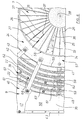
- the pole pieces 7, 8 are circular in a plan view and from accordingly machined, in plan view wedge-shaped ferrite modules composed, as this particular from the Fig. 6, an enlarged 5 shows a plan view of the illustration according to FIG. 5, and from FIG. 8 it can be seen that a top view of the upper coil box 9 together with the upper pole piece. 7 shows.
- the pole piece 7 further comprises an axial, tubular Recess 28 for forming a tubular pole piece. 7
- a Pol diharmonic Device covered by a pole plate 30, wherein the pole plate 30, the associated Pol dind Structure 29 laterally circumferentially surmounted and in the area Pol micnd vom 29 a recess 31 with less material thickness as in the adjoining area, in which the Pol micnd Applications 29 dives.
- separators 33 are inserted to form isolation / cooling columns, of which in the illustrations of Figures 5 and 6, only one is shown schematically and exemplarily inserted.
- the circulating Edge of Pol dichnd Structure 29 as well as the associated edge of Recess 31 rounded so that the insulation / cooling column 32 in a Ring gap 34 ends as a cooling air outlet.
- the upper coil box 9 is cuboid, wherein the associated Pol Nynd Structure 29 laterally circumferentially projecting area of Polschuhplatte 30 a pad gap-side coil box bottom wall 38th formed.
- coil box side walls 43, 44, 45, 46 at.
- a bobbin-top wall 47 attached.
- the coil box 9 also includes one the magnet coil 22 radially outside surrounding, thin-walled windbox inner wall, which from the bobbin bottom wall 38 with a cooling air inlet ring gap 49 is spaced.
- the bobbin bottom wall 38, the Spool box sidewalls 43, 44, 45 and 46, the spool box top panel 47 and the windbox inner wall form a circumferential wind box 50 on, wherein the cooling air supply to the windbox 50 here for example on the cover wall side Inlet openings 51, 52 and sidewall-side inlet openings 53 can take place.
- To these cooling air inlet openings 51, 52, 53 can be connected to a cooling air pump, not shown here, injected via the cooling air according to the arrows 54 in the windbox 50 can be.
- the magnetic coil 22 is further surrounded radially inwardly by an air guide wall 55, whereby between this and an adjacent pole piece wall 56 an annular gap 57 for the exit of the pole shoe cooling air according to the arrows 58 can be done.
- the magnet coil 22 has a support structure 40 for the coil windings 39 on, in the region of the magnetic coil 22 web-shaped bottom coil carrier 41 and lying above arranged, web-shaped cover-side bobbin 42 as associated coil carrier pairs. How this particular out 6 and Fig. 8 it can be seen, are the mutually associated coil carrier pairs from bottom-side coil support 41 and lid-side coil carrier 42 radially radially and from the adjacent coil carrier pair angularly spaced.
- one of the coil carrier pairs is in a lower image plane area shown without the lid-side bobbin 42.
- insulating rods 59 are z. B. formed as a ceramic round rods, wherein between the Isolierstäben 59 receiving compartments 60 are formed in which recorded the helical coil turns 39 and are held.
- the bobbin 41, 42 are, as shown in particular in FIG. 5 can be seen is, in each case wedge-shaped, so that the radially outer coil turns with their bottom coil winding areas farther from the bobbin bottom wall 38 are lifted off as the more radially inward Spulenwindungs Symposiume.
- the lid-side Coil carrier 42 radially externally releasably bolted to the top wall 47 and radially inwardly mounted on the spool box bottom wall 38 Support columns 64 also releasably bolted.
- Fig. 7 a schematic cross-section through the entire bobbin 9 shows is a shown alternative embodiment in which the lid-side bobbin are screwed from below with the top wall 47. Besides, here are still On the edge threaded rods 68 arranged on the one connection with another Components is possible. Otherwise the construction corresponds to the one like him in the enlarged detail of Fig. 5 is shown.
- the bottom-side bobbin 41 are connected to the bobbin bottom wall 38th screwed and / or glued.
- the coil carriers can 41, 42 each have receiving bores 65 into which the insulating rods 59 plugged in and held.
- the cooling air thus becomes over the z. B. acting as a pressure chamber windbox 50 on the bottom side Cooling air inlet ring gap 49 in the area of the lower coil winding areas fed, since there is the largest warming of the solenoid. Because the radially outer coil turns with their bottom side Coil winding areas farther from the coil box bottom wall 38 are lifted off as the more radially inner coil winding areas thus bounces the supplied via the cooling air fixtureringspalt 49 cooling air directly on the there staggered lower edges of the coil turns 39, where the largest heating of the coil by eddy currents in the copper produced by the Magnetic field arises.
- a further Throughflow opening 67 may be formed upwards. This is achieved that in connection with the air baffles 61, 62 more air to the outer Can windings.
Landscapes
- Health & Medical Sciences (AREA)
- Animal Behavior & Ethology (AREA)
- Biomedical Technology (AREA)
- Nuclear Medicine, Radiotherapy & Molecular Imaging (AREA)
- Radiology & Medical Imaging (AREA)
- Life Sciences & Earth Sciences (AREA)
- Engineering & Computer Science (AREA)
- General Health & Medical Sciences (AREA)
- Public Health (AREA)
- Veterinary Medicine (AREA)
- Magnetic Treatment Devices (AREA)
- Thermotherapy And Cooling Therapy Devices (AREA)
- Electrotherapy Devices (AREA)
- General Induction Heating (AREA)
Description
- Fig. 1
- eine schematische Schnittansicht durch einen Magnetfeldapplikator,
- Fig. 2
- eine schematische Draufsicht auf den Magnetfeldapplikator gemäß Fig. 1,
- Fig. 3
- eine schematische Seitenansicht des Magnetfeldapplikators gemäß Fig. 1,
- Fig. 4
- eine schematische, perspektivische und vergrößerte Darstellung des Aufbaus quaderförmiger Ferritbausteine,
- Fig. 5
- eine schematische, vergrößerte Darstellung der Einzelheit A aus Fig. 1,
- Fig. 6
- eine schematische, vergrößerte Draufsicht entsprechend Fig. 5,
- Fig. 7
- ein schematischer Querschnitt durch einen oberen Spulenkasten mitsamt zugeordnetem Polschuh gemäß einer alternativen Ausführungsform, und
- Fig. 8
- eine schematische Draufsicht auf einen Spulenkasten mit zugeordnetem Polschuh und zugeordneter Magnetspule.
Claims (13)
- Magnetspulenanordnung eines Magnetfeldapplikators (1) zur Aufheizung von magnetischen oder magnetisierbaren Substanzen oder Festkörpern in biologischem Gewebe,
mit einem kühlbaren Magnetjoch (2) mit zwei gegenüberliegenden, durch einen Befeldungsspalt beabstandeten Polschuhen (7, 8) am Magnetjoch (2), wobei zur Erzeugung eines Magnetwechselfeldes zwei jeweils einem Polschuh zugeordnete Magnetspulen (22) vorgesehen sind, die als Scheibenspulen mit schneckenförmig verlaufenden Spulenwindungen ausgebildet sind und jeweils das Polschuhende des zugeordneten Polschuhs (7, 8) mit einem dazwischenliegenden umlaufenden Magnetspule/Polschuh-Spalt (24) ringförmig umfassen,
dadurch gekennzeichnet, dass jeweils die Magnetspule (22) zur Umströmung ihrer Windungen mit Kühlluft in einem den zugeordneten Polschuh (7, 8) ringförmig umfassenden Spulenkasten (9, 10) angebracht ist, und
dass der Spulenkasten (9, 10) wenigstens eine Kühlluft-Einströmöffnung (51, 52, 53) zum Anschluss einer Kühlluftpumpe und wenigstens eine Kühlluft-Ausströmöffnung (57, 66) aufweist. - Magnetspulenanordnung nach Anspruch 1, dadurch gekennzeichnet, dass das Magnetjoch (2) aus quaderförmigen Ferritbausteinen (16) zusammengesetzt ist, deren Flächen gegebenenfalls von Sinterschichten befreit und plan-parallel geschliffen sind, wobei die quaderförmigen Ferritbausteine (16) aus aneinandergereihten, im Magnetjoch (2) längs des Magnetflusses (17) ausgerichteten Ferritplatten bestehen, die quer zum Magnetfluss (17) durch Isolations-/Kühlungs-Spalte (19) voneinander getrennt sind, durch die Kühlluft (21) leitbar ist und die längs des Magnetflusses (17) über einen nur schmalen Anlagespalt aneinander liegen und in die Isolations-/Kühlungs-Spalte (19) vorzugsweise in Seitenbereichen Separatoren (20) aus Kunststoff eingefügt sind, über die die Ferritplatten zu Ferritbausteinen (16) als Jochelemente verklebt sind,
dass runde Polschuhe (7, 8) aus entsprechend bearbeiteten, in der Draufsicht keilförmigen Ferritbausteinen (25) zusammengesetzt sind, wobei
zwischen die keilförmigen Ferritbausteine (25) zur Bildung von Isolations-/Kühlungs-Spalten Separatoren (27) eingefügt sind, über die benachbarte Ferritbausteine (25) miteinander zu einem Polschuh (7) verklebt sind, und
eine axiale, rohrförmige Aussparung (28) zur Bildung jeweils eines rohrförmigen Polschuhs (7) vorgesehen ist und durch die Aussparung (28) Kühlluft einleitbar ist. - Magnetspulenanordnung nach Anspruch 1 oder Anspruch 2, dadurch gekennzeichnet, dass die Polschuhendflächen (29) jeweils durch eine Polschuhplatte (30) abgedeckt sind und die Polschuhplatte (30) unter Bildung eines Bereichs einer befeldungsspaltseitigen Spulenkasten-Bodenwand (38) die jeweils zugeordnete Polschuhendfläche (29) seitlich umlaufend überragt, und
dass zwischen einer Polschuhendfläche (29) und der Polschuhplatte (30) zur Bildung von Isolations-/Kühlungs-Spalten (32) Separatoren (33) eingefügt sind. - Magnetspulenanordnung nach Anspruch 3, dadurch gekennzeichnet, dass die Polschuhplatte (30) im Bereich der Polschuhendfläche (29) eine Vertiefung (31) mit geringerer Materialstärke als im Bereich der Spulenkasten-Bodenwand (38) aufweist, in die die Polschuhendfläche (29) eintaucht, wobei die umlaufende Kante der Polschuhendfläche (29) abgerundet ist und dort die Isolations-/Kühlungs-Spalten (32) in einem Ringspalt (34) als Kühlluftaustritt enden.
- Magnetspulenanordnung nach einem der Ansprüche 1 bis Anspruch 3, dadurch gekennzeichnet, dass die Polschuhe (7, 8) in einer Draufsicht kreisrund ausgebildet sind und mit gegeneinander weisenden, parallel ausgerichteten Polschuhkreisflächen als Polschuhendflächen im Abstand des Befeldungsspalts (12) gegenüberliegen,
dass die Magnetspulen (22) entsprechend kreisringförmig ausgebildet sind,
dass ein Spulenkasten (9, 10) quaderförmig das zugeordnete Polschuhende und die dieses Polschuhende umgebende Magnetspule (22) umfasst, und
dass die wenigstens eine Kühlluft-Einströmöffnung (51, 52, 53) in einer Spulenkasten-Seitenwand (43) und/oder in wenigstens einem Eckbereich einer Spulenkasten-Deckelwand (47) angeordnet ist. - Magnetspulenanordnung nach einem der Ansprüche 1 bis Anspruch 5, dadurch gekennzeichnet, dass die Magnetspule (22) eine Stützstruktur (40) für die Spulenwindungen (39) aufweist, dergestalt
dass im Bereich der Magnetspule (22) stegförmige bodenseitige Spulenträger (41) und darüber liegend angeordnete, stegförmige deckelseitige Spulenträger (42) als zugeordnete Spulenträgerpaare (41, 42) vorgesehen sind, die radial strahlenförmig und gegeneinander winkelversetzt angeordnet sind,
dass paarweise zugeordnete Spulenträger (41, 42) jeweils durch radial beabstandete und etwa axial ausgerichtete Isolierstäbe (59) verbunden sind, und
dass dadurch zwischen den Isolierstäben (59) Aufnahmefächer (60) gebildet sind, in denen die schneckenförmig verlaufenden Spulenwindungen (39) aufgenommen und gehalten sind, dergestalt,
dass durch die Steghöhe der bodenseitigen Spulenträger (41) die Spulenwindungen (39) unter Bildung eines radial äußeren Kühlluft-Eintrittringspalts (49) gegenüber der Spulenkasten-Bodenwand (38) abgehoben sind, wobei Kühlluft weiter durch die von den Isolierstäben (59) bestimmten Zwischenspalte führbar ist und die Bereiche (66) zwischen den deckelseitigen Spulenträgern (42) über den nicht abgedeckten Spulenwindungen (39) Kühlluft-Ausströmöffnungen bilden. - Magnetspulenanordnung nach Anspruch 6, dadurch gekennzeichnet, dass die Isolierstäbe (59) als Keramik-Rundstäbe ausgebildet sind.
- Magnetspulenanordnung nach Anspruch 6 oder Anspruch 7, dadurch gekennzeichnet, dass die Spulenkasten-Bodenwand (38), die Spulenkasten-Seitenwände (43, 44, 45, 46), die Spulenkasten-Deckelwand (47) sowie eine die Magnetspule (22) radial außen umgebende, dünnwandige Windkasteninnenwand (48), welche von der Spulenkasten-Bodenwand (38) mit dem Kühlluft-Eintrittringspalt (49) beabstandet ist, einen umlaufenden Windkasten (50) bilden und
dass die Magnetspule (22) radial innen von einer Luftführungswand (55) umgeben ist, wodurch zwischen dieser Luftführungswand (55) und einer benachbarten Polschuhwand (56) ein Ringspalt (24, 57) zum Austritt der Polschuh-Kühlluft hergestellt ist. - Magnetspulenanordnung nach einem der Ansprüche 6 bis Anspruch 8, dadurch gekennzeichnet, dass die Spulenträger (41, 42) keilförmig ausgebildet sind, dergestalt, dass die radial äußeren Spulenwindungen (39) mit ihren bodenseitigen Spulenwindungsbereichen weiter von der Spulenkasten-Bodenwand (38) abgehoben sind als die weiter radial innen liegenden Spulenwindungsbereiche.
- Magnetspulenanordnung nach Anspruch 9, dadurch gekennzeichnet, dass sich ausgehend vom Kühlluft-Eintrittringspalt (49) im Keilbereich zwischen den bodenseitigen Spulenträgern (41) etwa bodenparallele Luftleitplatten (61, 62) erstrecken, wobei jeweils eine bodennähere Luftleitplatte (62) länger und breiter ausgebildet ist als eine jeweils darüber liegende zugeordnete Luftleitplatte (61).
- Magnetspulenanordnung nach Anspruch 10, dadurch gekennzeichnet, dass die Luftleitplatten (61, 62) über Abstandssäulen (63) und/oder Distanzringe mit der Spulenkasten-Bodenwand (38) verbunden sind.
- Magnetspulenanordnung nach einem der Ansprüche 6 bis Anspruch 11, dadurch gekennzeichnet, dass die Spulenträger Aufnahmebohrungen (65) aufweisen, in die die Isolierstäbe (59) eingesteckt und gehalten sind,
dass die bodenseitigen Spulenträger (41) mit der Spulenkasten-Bodenwand (38) verschraubt und/oder verklebt sind,
dass die deckelseitigen Spulenträger (42) radial außen lösbar mit der Deckelwand (47) verschraubt sind und radial innen mit auf der Spulenkasten-Bodenwand (38) angebrachten Stützsäulen (64) lösbar verschraubt sind,
dass durch Schraub- und/oder Klebeverbindungen zwischen der Spulenkasten-Bodenwand (38), den Spulenkasten-Seitenwänden (43, 44, 45, 46) und der Spulenkasten-Deckelwand (47) ein stabiler Spulenkasten-Aufbau vorliegt, der über Verbindungselemente mit einem benachbarten Magnetjochteil verbindbar ist. - Magnetspulenanordnung nach einem der Ansprüche 1 bis 12, dadurch gekennzeichnet, dass das Magnetjoch (2) in einer M-Form als Drei-Schenkel-Anordnung ausgebildet ist, mit zwei beabstandeten, parallelen Vertikaljochteilen (3, 4) gleicher Geometrie und mit zwei dazwischen angeschlossenen Querjochteilen (5, 6) mit jeweils in deren Mitte angeordneten und aufeinander zugerichteten Polschuhen (7, 8), wovon wenigstens ein Querjochteil (5, 6) mit angeschlossenem Polschuh (7, 8) und zugeordneter Magnetspule (22) als Baueinheit relativ zum anderen Querjochteil (5, 6) zur Einstellung der Befeldungsspaltweite (12) verstellbar ist.
Applications Claiming Priority (2)
| Application Number | Priority Date | Filing Date | Title |
|---|---|---|---|
| DE10109105 | 2001-02-24 | ||
| DE10109105A DE10109105C2 (de) | 2001-02-24 | 2001-02-24 | Magnetspulenanordnung eines Magnetfeldapplikators zur Aufheizung von magnetischen oder magnetisierbaren Substanzen oder Festkörpern in biologischem Gewebe |
Publications (3)
| Publication Number | Publication Date |
|---|---|
| EP1234598A2 EP1234598A2 (de) | 2002-08-28 |
| EP1234598A3 EP1234598A3 (de) | 2003-10-22 |
| EP1234598B1 true EP1234598B1 (de) | 2005-09-28 |
Family
ID=7675464
Family Applications (1)
| Application Number | Title | Priority Date | Filing Date |
|---|---|---|---|
| EP02001638A Expired - Lifetime EP1234598B1 (de) | 2001-02-24 | 2002-01-24 | Magnetspulenanordnung eines Magnetfeldapplikators zur Aufheizung von magnetischen oder magnetisierbaren Substanzen oder Festkörpern in biologischem Gewebe |
Country Status (8)
| Country | Link |
|---|---|
| US (1) | US6737618B2 (de) |
| EP (1) | EP1234598B1 (de) |
| JP (1) | JP4297643B2 (de) |
| CN (1) | CN1261174C (de) |
| AT (1) | ATE305326T1 (de) |
| AU (1) | AU784762B2 (de) |
| CA (1) | CA2370514C (de) |
| DE (2) | DE10109105C2 (de) |
Families Citing this family (20)
| Publication number | Priority date | Publication date | Assignee | Title |
|---|---|---|---|---|
| US7731648B2 (en) * | 2001-07-25 | 2010-06-08 | Aduro Biotech | Magnetic nanoscale particle compositions, and therapeutic methods related thereto |
| US7951061B2 (en) * | 2001-07-25 | 2011-05-31 | Allan Foreman | Devices for targeted delivery of thermotherapy, and methods related thereto |
| US20040156846A1 (en) * | 2003-02-06 | 2004-08-12 | Triton Biosystems, Inc. | Therapy via targeted delivery of nanoscale particles using L6 antibodies |
| US7218195B2 (en) * | 2003-10-01 | 2007-05-15 | General Electric Company | Method and apparatus for magnetizing a permanent magnet |
| US7771383B2 (en) | 2004-10-22 | 2010-08-10 | Medegen, Inc. | Fluid control device with valve and methods of use |
| CN100435763C (zh) * | 2005-11-04 | 2008-11-26 | 中国科学院理化技术研究所 | 结合热籽及血管支架实现血管内加热的肿瘤全身热疗装置 |
| JP4591572B2 (ja) * | 2008-08-05 | 2010-12-01 | セイコーエプソン株式会社 | コイルアセンブリおよびスイッチング型電源装置 |
| WO2010026638A1 (ja) * | 2008-09-04 | 2010-03-11 | 株式会社ナノセラピー研究所 | 抗制御性t細胞抗体と磁性微粒子を含む悪性腫瘍の温熱治療用キット、及びその温熱治療法 |
| CN103390482B (zh) * | 2013-06-24 | 2015-11-04 | 中国科学院空间科学与应用研究中心 | 一种大截面均匀可调稳定与交变磁场产生装置及方法 |
| CN103325524A (zh) * | 2013-06-25 | 2013-09-25 | 江苏烨泰玻璃有限公司 | 一种用于玻璃行业的风冷式电磁铁 |
| JP5893689B2 (ja) * | 2014-07-25 | 2016-03-23 | 株式会社Ifg | 連続磁気パルス発生装置 |
| CN104821675B (zh) * | 2015-04-29 | 2018-01-05 | 哈尔滨理工大学 | 一种能提高冷却效果的隐极电机端部磁屏蔽装置 |
| CN105169560B (zh) * | 2015-06-12 | 2016-06-15 | 郑州轻工业学院 | 一种控制磁纳米粒子加热区域的装置及方法 |
| PL237437B1 (pl) * | 2018-10-06 | 2021-04-19 | Univ Im Adama Mickiewicza W Poznaniu | Urządzenie do wytwarzania rotującego pola magnetycznego |
| CN111383816B (zh) * | 2020-01-08 | 2021-09-17 | 横店集团东磁股份有限公司 | 一种减少磁瓦掉角的充磁夹具 |
| CN111952035B (zh) * | 2020-07-14 | 2022-03-08 | 中国科学院电工研究所 | 一种摆动磁场发生装置及其控制方法 |
| US12033787B2 (en) | 2021-08-04 | 2024-07-09 | Medtronic, Inc. | Thermal transfer system and method |
| US12217900B2 (en) | 2021-08-04 | 2025-02-04 | Medtronic, Inc. | Thermal transfer system and method |
| US12283823B2 (en) | 2021-08-04 | 2025-04-22 | Medtronic, Inc. | Thermal transfer system and method |
| CN120878391B (zh) * | 2025-09-25 | 2025-12-12 | 四川红华实业有限公司 | 一种可调极靴间隙的电磁铁及其调节方法 |
Family Cites Families (10)
| Publication number | Priority date | Publication date | Assignee | Title |
|---|---|---|---|---|
| FR1043701A (fr) * | 1951-10-10 | 1953-11-10 | Materiel Electro Magnetique S | Perfectionnements aux électro-aimants |
| US4378548A (en) * | 1981-03-23 | 1983-03-29 | Magnetics International, Inc. | Lifting magnet incorporating cooling means |
| DE3422930C2 (de) * | 1983-07-21 | 1987-05-07 | Steinert Elektromagnetbau GmbH, 5000 Köln | Elektromagnet für Heißtransport und/oder für Magnetscheider |
| DE9006056U1 (de) * | 1990-05-29 | 1991-09-26 | Kraus, Werner, Dipl.-Ing., 8000 München | Applikatorspule für die Magnetfeldtherapie |
| US6023165A (en) * | 1992-09-28 | 2000-02-08 | Fonar Corporation | Nuclear magnetic resonance apparatus and methods of use and facilities for incorporating the same |
| US5935476A (en) * | 1996-01-16 | 1999-08-10 | Linlan Induction Ab | Device for heating a press tool using magnetic induction heating; press having such a device, and method of manufacture |
| AUPN978296A0 (en) * | 1996-05-10 | 1996-05-30 | Gray, Bruce N | Targeted hysteresis hyperthermia as a method for treating cancer |
| AUPP008197A0 (en) * | 1997-10-29 | 1997-11-20 | Paragon Medical Limited | Improved targeted hysteresis hyperthermia as a method for treating diseased tissue |
| US6227394B1 (en) * | 1998-06-09 | 2001-05-08 | Asahi Glass Company Ltd. | Glass bulb for a cathode ray tube and a method for producing a cathode ray tube |
| DE19937492C2 (de) * | 1999-08-07 | 2001-08-23 | Mfh Hyperthermiesysteme Gmbh | Magnetfeldapplikator zur Aufheizung von magnetischen oder magnetisierbaren Substanzen oder Festkörpern in biologischem Gewebe |
-
2001
- 2001-02-24 DE DE10109105A patent/DE10109105C2/de not_active Expired - Fee Related
-
2002
- 2002-01-24 AT AT02001638T patent/ATE305326T1/de active
- 2002-01-24 EP EP02001638A patent/EP1234598B1/de not_active Expired - Lifetime
- 2002-01-24 DE DE50204353T patent/DE50204353D1/de not_active Expired - Lifetime
- 2002-02-04 CA CA2370514A patent/CA2370514C/en not_active Expired - Lifetime
- 2002-02-13 JP JP2002034737A patent/JP4297643B2/ja not_active Expired - Fee Related
- 2002-02-21 AU AU16819/02A patent/AU784762B2/en not_active Ceased
- 2002-02-22 US US10/081,414 patent/US6737618B2/en not_active Expired - Lifetime
- 2002-02-22 CN CN02105113.5A patent/CN1261174C/zh not_active Expired - Fee Related
Also Published As
| Publication number | Publication date |
|---|---|
| AU1681902A (en) | 2002-08-29 |
| JP4297643B2 (ja) | 2009-07-15 |
| JP2002263203A (ja) | 2002-09-17 |
| DE10109105C2 (de) | 2003-01-09 |
| CA2370514C (en) | 2014-08-05 |
| CN1371753A (zh) | 2002-10-02 |
| DE50204353D1 (de) | 2006-02-09 |
| DE10109105A1 (de) | 2002-09-12 |
| EP1234598A3 (de) | 2003-10-22 |
| US6737618B2 (en) | 2004-05-18 |
| EP1234598A2 (de) | 2002-08-28 |
| CN1261174C (zh) | 2006-06-28 |
| AU784762B2 (en) | 2006-06-08 |
| CA2370514A1 (en) | 2002-08-24 |
| ATE305326T1 (de) | 2005-10-15 |
| US20020125975A1 (en) | 2002-09-12 |
Similar Documents
| Publication | Publication Date | Title |
|---|---|---|
| EP1234598B1 (de) | Magnetspulenanordnung eines Magnetfeldapplikators zur Aufheizung von magnetischen oder magnetisierbaren Substanzen oder Festkörpern in biologischem Gewebe | |
| EP1102609B1 (de) | Magnetfeldapplikator zur aufheizung von magnetischen oder magnetisierbaren substanzen oder festkörpern in biologischem gewebe | |
| EP3127218B1 (de) | Elektrischer hohlleiter für eine elektromagnetische maschine | |
| EP0712199A1 (de) | Transversalflussmaschine | |
| EP2463869A1 (de) | Induktives Bauelement mit verbesserten Kerneigenschaften | |
| EP3214736A1 (de) | Elektrische maschine für ein kraftfahrzeug, spulenträger für eine elektrische maschine und kraftfahrzeug | |
| DE4206562C2 (de) | Filtergehäuse | |
| WO2001010500A1 (de) | Magnetfeldapplikator zur aufheizung von magnetischen oder magnetisierbaren substanzen oder festkörpern in biologischem gewebe | |
| DE102018102944A1 (de) | Drosselspule mit Eisenkerneinheit und Spulen, Motorantriebsvorrichtung, Power Conditioner, und Maschine | |
| EP0688028A1 (de) | Elektromagnetischer Koppler | |
| DE3404457A1 (de) | Einrichtung zur kuehlung eines magnetsystems | |
| DE102015108104B4 (de) | LC Filter mit Funktion zur Kühlung einer AC Drossel und Leistungswandler | |
| DE3019720C2 (de) | Mikrowellenheizvorrichtung für umwälzbare Medien | |
| DE3443614A1 (de) | Elektromagnetische pumpe | |
| DE10048492A1 (de) | Axialfeldmaschine | |
| DE1801722A1 (de) | Transformator | |
| EP1869757B1 (de) | Primärteil eines linearmotors und linearmotor hiermit | |
| DE102017126599A1 (de) | Induktivität | |
| EP2975618B1 (de) | Kern für eine elektrische Induktionseinrichtung | |
| DE431844C (de) | Elektrische Maschine der Kuehlmanteltype, bei der die Kanaele fuer die Rueck-kuehlung des Innenkuehlmittels im Staenderblechpaket liegen, dessen Aussenflaeche von dem Mantelkuehlmittel bestrichen wird | |
| DE875824C (de) | Aus Scheibenspulen aufgebaute oelisolierte Roehrenwicklung fuer Hochspannungstransformatoren | |
| DE2115574A1 (de) | Elektromagnetische Vorrichtung, ins besondere für Mittelfrequenz | |
| DE2263675C3 (de) | Hochfrequenztransformator für Induktionsheizungsanlagen | |
| EP4508665A1 (de) | Transformator mit ringkern | |
| DE102023210830A1 (de) | Induktionsheizvorrichtung |
Legal Events
| Date | Code | Title | Description |
|---|---|---|---|
| PUAI | Public reference made under article 153(3) epc to a published international application that has entered the european phase |
Free format text: ORIGINAL CODE: 0009012 |
|
| AK | Designated contracting states |
Kind code of ref document: A2 Designated state(s): AT BE CH CY DE DK ES FI FR GB GR IE IT LI LU MC NL PT SE TR |
|
| AX | Request for extension of the european patent |
Free format text: AL;LT;LV;MK;RO;SI |
|
| PUAL | Search report despatched |
Free format text: ORIGINAL CODE: 0009013 |
|
| AK | Designated contracting states |
Kind code of ref document: A3 Designated state(s): AT BE CH CY DE DK ES FI FR GB GR IE IT LI LU MC NL PT SE TR |
|
| AX | Request for extension of the european patent |
Extension state: AL LT LV MK RO SI |
|
| 17P | Request for examination filed |
Effective date: 20040326 |
|
| 17Q | First examination report despatched |
Effective date: 20040430 |
|
| AKX | Designation fees paid |
Designated state(s): AT BE CH CY DE DK ES FI FR GB GR IE IT LI LU MC NL PT SE TR |
|
| GRAP | Despatch of communication of intention to grant a patent |
Free format text: ORIGINAL CODE: EPIDOSNIGR1 |
|
| GRAS | Grant fee paid |
Free format text: ORIGINAL CODE: EPIDOSNIGR3 |
|
| GRAA | (expected) grant |
Free format text: ORIGINAL CODE: 0009210 |
|
| AK | Designated contracting states |
Kind code of ref document: B1 Designated state(s): AT BE CH CY DE DK ES FI FR GB GR IE IT LI LU MC NL PT SE TR |
|
| PG25 | Lapsed in a contracting state [announced via postgrant information from national office to epo] |
Ref country code: IE Free format text: LAPSE BECAUSE OF FAILURE TO SUBMIT A TRANSLATION OF THE DESCRIPTION OR TO PAY THE FEE WITHIN THE PRESCRIBED TIME-LIMIT Effective date: 20050928 Ref country code: FI Free format text: LAPSE BECAUSE OF FAILURE TO SUBMIT A TRANSLATION OF THE DESCRIPTION OR TO PAY THE FEE WITHIN THE PRESCRIBED TIME-LIMIT Effective date: 20050928 |
|
| REG | Reference to a national code |
Ref country code: GB Ref legal event code: FG4D Free format text: NOT ENGLISH |
|
| REG | Reference to a national code |
Ref country code: CH Ref legal event code: EP |
|
| REG | Reference to a national code |
Ref country code: IE Ref legal event code: FG4D Free format text: LANGUAGE OF EP DOCUMENT: GERMAN |
|
| PG25 | Lapsed in a contracting state [announced via postgrant information from national office to epo] |
Ref country code: SE Free format text: LAPSE BECAUSE OF FAILURE TO SUBMIT A TRANSLATION OF THE DESCRIPTION OR TO PAY THE FEE WITHIN THE PRESCRIBED TIME-LIMIT Effective date: 20051228 Ref country code: GR Free format text: LAPSE BECAUSE OF FAILURE TO SUBMIT A TRANSLATION OF THE DESCRIPTION OR TO PAY THE FEE WITHIN THE PRESCRIBED TIME-LIMIT Effective date: 20051228 Ref country code: DK Free format text: LAPSE BECAUSE OF FAILURE TO SUBMIT A TRANSLATION OF THE DESCRIPTION OR TO PAY THE FEE WITHIN THE PRESCRIBED TIME-LIMIT Effective date: 20051228 |
|
| REG | Reference to a national code |
Ref country code: CH Ref legal event code: NV Representative=s name: PA ALDO ROEMPLER |
|
| PG25 | Lapsed in a contracting state [announced via postgrant information from national office to epo] |
Ref country code: ES Free format text: LAPSE BECAUSE OF FAILURE TO SUBMIT A TRANSLATION OF THE DESCRIPTION OR TO PAY THE FEE WITHIN THE PRESCRIBED TIME-LIMIT Effective date: 20060108 |
|
| GBT | Gb: translation of ep patent filed (gb section 77(6)(a)/1977) |
Effective date: 20060103 |
|
| PG25 | Lapsed in a contracting state [announced via postgrant information from national office to epo] |
Ref country code: MC Free format text: LAPSE BECAUSE OF NON-PAYMENT OF DUE FEES Effective date: 20060131 Ref country code: LU Free format text: LAPSE BECAUSE OF NON-PAYMENT OF DUE FEES Effective date: 20060131 Ref country code: BE Free format text: LAPSE BECAUSE OF NON-PAYMENT OF DUE FEES Effective date: 20060131 |
|
| REF | Corresponds to: |
Ref document number: 50204353 Country of ref document: DE Date of ref document: 20060209 Kind code of ref document: P |
|
| PG25 | Lapsed in a contracting state [announced via postgrant information from national office to epo] |
Ref country code: PT Free format text: LAPSE BECAUSE OF FAILURE TO SUBMIT A TRANSLATION OF THE DESCRIPTION OR TO PAY THE FEE WITHIN THE PRESCRIBED TIME-LIMIT Effective date: 20060228 |
|
| REG | Reference to a national code |
Ref country code: IE Ref legal event code: FD4D |
|
| ET | Fr: translation filed | ||
| PLBE | No opposition filed within time limit |
Free format text: ORIGINAL CODE: 0009261 |
|
| STAA | Information on the status of an ep patent application or granted ep patent |
Free format text: STATUS: NO OPPOSITION FILED WITHIN TIME LIMIT |
|
| 26N | No opposition filed |
Effective date: 20060629 |
|
| BERE | Be: lapsed |
Owner name: MFH HYPERTHERMIESYSTEME G.M.B.H. Effective date: 20060131 |
|
| PG25 | Lapsed in a contracting state [announced via postgrant information from national office to epo] |
Ref country code: TR Free format text: LAPSE BECAUSE OF FAILURE TO SUBMIT A TRANSLATION OF THE DESCRIPTION OR TO PAY THE FEE WITHIN THE PRESCRIBED TIME-LIMIT Effective date: 20050928 |
|
| REG | Reference to a national code |
Ref country code: CH Ref legal event code: PCAR Free format text: ALDO ROEMPLER PATENTANWALT;BRENDENWEG 11 POSTFACH 154;9424 RHEINECK (CH) |
|
| PG25 | Lapsed in a contracting state [announced via postgrant information from national office to epo] |
Ref country code: CY Free format text: LAPSE BECAUSE OF FAILURE TO SUBMIT A TRANSLATION OF THE DESCRIPTION OR TO PAY THE FEE WITHIN THE PRESCRIBED TIME-LIMIT Effective date: 20050928 |
|
| REG | Reference to a national code |
Ref country code: FR Ref legal event code: ST Effective date: 20120928 |
|
| REG | Reference to a national code |
Ref country code: FR Ref legal event code: RN Effective date: 20121119 |
|
| PG25 | Lapsed in a contracting state [announced via postgrant information from national office to epo] |
Ref country code: FR Free format text: LAPSE BECAUSE OF NON-PAYMENT OF DUE FEES Effective date: 20120131 |
|
| REG | Reference to a national code |
Ref country code: FR Ref legal event code: FC Effective date: 20130122 |
|
| PGRI | Patent reinstated in contracting state [announced from national office to epo] |
Ref country code: FR Effective date: 20130207 |
|
| REG | Reference to a national code |
Ref country code: FR Ref legal event code: PLFP Year of fee payment: 15 |
|
| REG | Reference to a national code |
Ref country code: FR Ref legal event code: PLFP Year of fee payment: 16 |
|
| REG | Reference to a national code |
Ref country code: FR Ref legal event code: PLFP Year of fee payment: 17 |
|
| REG | Reference to a national code |
Ref country code: DE Ref legal event code: R082 Ref document number: 50204353 Country of ref document: DE Representative=s name: NEUBAUER LIEBL BIERSCHNEIDER, DE Ref country code: DE Ref legal event code: R081 Ref document number: 50204353 Country of ref document: DE Owner name: MAGFORCE AG, DE Free format text: FORMER OWNER: MAGFORCE NANOTECHNOLOGIES GMBH, 14050 BERLIN, DE Ref country code: DE Ref legal event code: R081 Ref document number: 50204353 Country of ref document: DE Owner name: MAGFORCE AG, DE Free format text: FORMER OWNER: MFH HYPERTHERMIESYSTEME GMBH, 12247 BERLIN, DE Ref country code: DE Ref legal event code: R081 Ref document number: 50204353 Country of ref document: DE Owner name: MAGFORCE NANOTECHNOLOGIES AG, DE Free format text: FORMER OWNER: MAGFORCE NANOTECHNOLOGIES GMBH, 14050 BERLIN, DE Ref country code: DE Ref legal event code: R081 Ref document number: 50204353 Country of ref document: DE Owner name: MAGFORCE NANOTECHNOLOGIES AG, DE Free format text: FORMER OWNER: MFH HYPERTHERMIESYSTEME GMBH, 12247 BERLIN, DE |
|
| REG | Reference to a national code |
Ref country code: DE Ref legal event code: R082 Ref document number: 50204353 Country of ref document: DE Representative=s name: NEUBAUER LIEBL BIERSCHNEIDER, DE Ref country code: DE Ref legal event code: R081 Ref document number: 50204353 Country of ref document: DE Owner name: MAGFORCE AG, DE Free format text: FORMER OWNER: MAGFORCE NANOTECHNOLOGIES AG, 10589 BERLIN, DE |
|
| REG | Reference to a national code |
Ref country code: GB Ref legal event code: 732E Free format text: REGISTERED BETWEEN 20181206 AND 20181212 |
|
| REG | Reference to a national code |
Ref country code: GB Ref legal event code: 732E Free format text: REGISTERED BETWEEN 20190801 AND 20190807 |
|
| PGFP | Annual fee paid to national office [announced via postgrant information from national office to epo] |
Ref country code: NL Payment date: 20200126 Year of fee payment: 19 Ref country code: IT Payment date: 20200131 Year of fee payment: 19 Ref country code: AT Payment date: 20200122 Year of fee payment: 19 Ref country code: DE Payment date: 20200225 Year of fee payment: 19 Ref country code: GB Payment date: 20200122 Year of fee payment: 19 |
|
| PGFP | Annual fee paid to national office [announced via postgrant information from national office to epo] |
Ref country code: CH Payment date: 20200306 Year of fee payment: 19 |
|
| PGFP | Annual fee paid to national office [announced via postgrant information from national office to epo] |
Ref country code: FR Payment date: 20200130 Year of fee payment: 19 |
|
| REG | Reference to a national code |
Ref country code: DE Ref legal event code: R119 Ref document number: 50204353 Country of ref document: DE |
|
| REG | Reference to a national code |
Ref country code: CH Ref legal event code: PL |
|
| REG | Reference to a national code |
Ref country code: NL Ref legal event code: MM Effective date: 20210201 |
|
| REG | Reference to a national code |
Ref country code: AT Ref legal event code: MM01 Ref document number: 305326 Country of ref document: AT Kind code of ref document: T Effective date: 20210124 |
|
| GBPC | Gb: european patent ceased through non-payment of renewal fee |
Effective date: 20210124 |
|
| PG25 | Lapsed in a contracting state [announced via postgrant information from national office to epo] |
Ref country code: AT Free format text: LAPSE BECAUSE OF NON-PAYMENT OF DUE FEES Effective date: 20210124 Ref country code: NL Free format text: LAPSE BECAUSE OF NON-PAYMENT OF DUE FEES Effective date: 20210201 Ref country code: FR Free format text: LAPSE BECAUSE OF NON-PAYMENT OF DUE FEES Effective date: 20210131 |
|
| PG25 | Lapsed in a contracting state [announced via postgrant information from national office to epo] |
Ref country code: LI Free format text: LAPSE BECAUSE OF NON-PAYMENT OF DUE FEES Effective date: 20210131 Ref country code: CH Free format text: LAPSE BECAUSE OF NON-PAYMENT OF DUE FEES Effective date: 20210131 Ref country code: GB Free format text: LAPSE BECAUSE OF NON-PAYMENT OF DUE FEES Effective date: 20210124 Ref country code: DE Free format text: LAPSE BECAUSE OF NON-PAYMENT OF DUE FEES Effective date: 20210803 |
|
| PG25 | Lapsed in a contracting state [announced via postgrant information from national office to epo] |
Ref country code: IT Free format text: LAPSE BECAUSE OF NON-PAYMENT OF DUE FEES Effective date: 20210124 |