EP1234644A2 - Stanzstation zum Austrennen von Teilen aus thermoplastischem Kunststoff - Google Patents
Stanzstation zum Austrennen von Teilen aus thermoplastischem Kunststoff Download PDFInfo
- Publication number
- EP1234644A2 EP1234644A2 EP02002730A EP02002730A EP1234644A2 EP 1234644 A2 EP1234644 A2 EP 1234644A2 EP 02002730 A EP02002730 A EP 02002730A EP 02002730 A EP02002730 A EP 02002730A EP 1234644 A2 EP1234644 A2 EP 1234644A2
- Authority
- EP
- European Patent Office
- Prior art keywords
- punching
- cross bridge
- guide columns
- bridge
- cutting
- Prior art date
- Legal status (The legal status is an assumption and is not a legal conclusion. Google has not performed a legal analysis and makes no representation as to the accuracy of the status listed.)
- Granted
Links
Images



Classifications
-
- B—PERFORMING OPERATIONS; TRANSPORTING
- B29—WORKING OF PLASTICS; WORKING OF SUBSTANCES IN A PLASTIC STATE IN GENERAL
- B29C—SHAPING OR JOINING OF PLASTICS; SHAPING OF MATERIAL IN A PLASTIC STATE, NOT OTHERWISE PROVIDED FOR; AFTER-TREATMENT OF THE SHAPED PRODUCTS, e.g. REPAIRING
- B29C51/00—Shaping by thermoforming, i.e. shaping sheets or sheet like preforms after heating, e.g. shaping sheets in matched moulds or by deep-drawing; Apparatus therefor
- B29C51/26—Component parts, details or accessories; Auxiliary operations
- B29C51/44—Removing or ejecting moulded articles
- B29C51/445—Removing or ejecting moulded articles from a support after moulding, e.g. by cutting
-
- B—PERFORMING OPERATIONS; TRANSPORTING
- B26—HAND CUTTING TOOLS; CUTTING; SEVERING
- B26D—CUTTING; DETAILS COMMON TO MACHINES FOR PERFORATING, PUNCHING, CUTTING-OUT, STAMPING-OUT OR SEVERING
- B26D7/00—Details of apparatus for cutting, cutting-out, stamping-out, punching, perforating, or severing by means other than cutting
- B26D7/26—Means for mounting or adjusting the cutting member; Means for adjusting the stroke of the cutting member
-
- B—PERFORMING OPERATIONS; TRANSPORTING
- B26—HAND CUTTING TOOLS; CUTTING; SEVERING
- B26F—PERFORATING; PUNCHING; CUTTING-OUT; STAMPING-OUT; SEVERING BY MEANS OTHER THAN CUTTING
- B26F1/00—Perforating; Punching; Cutting-out; Stamping-out; Apparatus therefor
- B26F1/38—Cutting-out; Stamping-out
- B26F1/40—Cutting-out; Stamping-out using a press, e.g. of the ram type
-
- B—PERFORMING OPERATIONS; TRANSPORTING
- B29—WORKING OF PLASTICS; WORKING OF SUBSTANCES IN A PLASTIC STATE IN GENERAL
- B29C—SHAPING OR JOINING OF PLASTICS; SHAPING OF MATERIAL IN A PLASTIC STATE, NOT OTHERWISE PROVIDED FOR; AFTER-TREATMENT OF THE SHAPED PRODUCTS, e.g. REPAIRING
- B29C2793/00—Shaping techniques involving a cutting or machining operation
- B29C2793/0009—Cutting out
-
- B—PERFORMING OPERATIONS; TRANSPORTING
- B29—WORKING OF PLASTICS; WORKING OF SUBSTANCES IN A PLASTIC STATE IN GENERAL
- B29C—SHAPING OR JOINING OF PLASTICS; SHAPING OF MATERIAL IN A PLASTIC STATE, NOT OTHERWISE PROVIDED FOR; AFTER-TREATMENT OF THE SHAPED PRODUCTS, e.g. REPAIRING
- B29C2793/00—Shaping techniques involving a cutting or machining operation
- B29C2793/009—Shaping techniques involving a cutting or machining operation after shaping
Definitions
- the invention relates to a punching station for removing parts from thermoplastic plastic, which is in a thermoforming machine in a thermoplastic film are molded according to the genus of Main claim.
- a generic punching station integrated in a thermoforming machine, is known from DE 31 18 529 A1.
- This document shows an education of a Punching station in such a way that the punching tool can be moved to a height Table is arranged, which is guided on stationary guide columns and over a Toggle lever drive is moved.
- the guide columns are with a cross bridge connected to which the toggle lever drive is articulated.
- the foil tape to be punched out is kept ready, it serves as Punching opposite position.
- the problem with this adjustment device is that the thread flanks between the threaded bushing and the external thread on the guide columns have to have a certain amount of play to be able to make an adjustment, without damaging the thread flanks. This is comparable to one Mother being twisted on a screw. A certain axial play is for slight twisting required.
- the invention has for its object a punching station in a simple manner to be designed so that the formation of fine plastic strips and dust-like Particles is prevented. At the same time, wear on the cutting edges is to be reduced and thus the service life of the punching tool and the punching counter be extended. The torque to adjust the cross bridge to the Guide columns and wear on the adjustment thread should be reduced become.
- this supporting spring elements that press against the cross bridge on the one hand brought about a weight balance and with the differential force (Spring force minus weight) the thread flanks in the direction pressed into which the punching force also acts.
- the cross bridge the is pressed against the underside of the collar of the threaded bush.
- FIG. 1 shows a thermoforming machine 1 for shaping a film web 2 Molded parts 3.
- the film web 2 is conveyed by a transport device 4 cyclically a heater 5, the forming station 6, the punching station 7 and possibly one Stacking device 8 supplied.
- the invention relates to the punching station 7, which has a lower punching table 9 has which is rigid as shown or is vertically movable. On him is a punching pad, not shown, made of sheet metal or cardboard, lies on this the film web 2 when punching. A is used to punch out the parts 3 Punching tool 10, which has a cutting line 11 and at one height-adjustable table 12 is attached.
- This table 12 is stationary Guide columns 13 via a drive 14 fastened to the cross bridge 17 adjustable in height, this preferably in the form of a toggle lever drive 15 is designed to achieve high punching forces.
- the punching by means of a punching tool provided with a cutting line 11 10 requires an exact adjustment of the end position of the table 12 to one Damage to cutting line 11 due to excessive force build-up after Avoid cutting out parts 3.
- an adjustment device 16 that the position of the cross bridge 17 to the guide columns 13 are adjusted can.
- the upper end of each guide column 13 has one Threaded pin 18 on which a threaded bushing 19 is seated.
- Threaded pin 18 is provided, which is on the one hand on the Cross bridge 17 supports, on the other hand by a mounted on the cross bridge 17 Retaining ring 21 is supported.
- the optimal setting of the cross bridge 17 becomes too the guide columns 13 and thus the lower end position of the table 12 Trials identified.
- the cross bridge 17 is adjusted downwards until good ones Punching results can be achieved.
- FIG 2 shows the problems with this known adjusting device 16, which in existing game 24 between the threads and the game 25 between the federal government 20 and cross bridge 17 or retaining ring 21 available for functional reasons have to be.
- This game is in the range of a few 1/10 millimeters, but this is enough to adversely affect the punching and durability of the To impact punch 10.
- Due to the weight of cross bridge 17 and punching tool 10 and parts of the drive 14 is the game 24, 25 distributed on one side, as shown in Figure 2 on the left.
- the punching force causes the cross bridge 17 to have a height is loaded upwards and thereby the game 24, 25 on the other side shifts, as shown in Figure 2 on the right. That means that after Cutting the molded parts 3 to be punched out the entire weight of the parts pressed above rests on the section line 11. It has been shown that this leads to a minimal deformation of the cutting edge, which leads to the formation of so-called angel hair and dust-like particles.
- a support 26 attached, on the one Spring element in the form of a coil spring 27 is supported.
- the coil spring 27 presses against the cross bridge 17, with a force in all positions the cross bridge 17 is higher than the weight of the cross bridge 17 inclusive attached parts, so that the game 24, 25 to that shown in Figure 2 on the right Location is shifted. This means that the punching process itself does not release any play off and there is a rigid position of the adjustment unit.
- Coil springs 27 with a large spring travel can also be selected with a corresponding change in position of the cross bridge 17 to the Guide columns 13 with sufficient spring force to counter the weight Act.
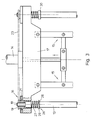
- a support ring 28 can be used as a support in a simple manner held disc 29 serve. Even with a simple paragraph or collar 30 - as shown in Figure 3 on the right guide column 13 - this edition is on easy to manufacture.
- a second embodiment - shown on the left in FIG. 4 - also shows a solution Tension springs 30 with which the same effect is achieved. This will be at the top of at least two or all of the guide columns 13 attached to a plate 31 of the tension springs 30 are articulated on the one hand, while on the other hand on the Cross bridge 17 are attached.
- Figure 4 on the right shows a variant of the arrangement of the compression springs 27 and Tension springs 30 in such a way that they on the one hand on the stationary frame 32 are articulated, on the other hand act on the cross bridge 17. That's how they support themselves Compression springs 27 on the cross member 33 connected to the frame 32 Tension springs 30 are attached to the cross member 34, which is also part of the frame 32 is.
Landscapes
- Engineering & Computer Science (AREA)
- Mechanical Engineering (AREA)
- Life Sciences & Earth Sciences (AREA)
- Forests & Forestry (AREA)
- Perforating, Stamping-Out Or Severing By Means Other Than Cutting (AREA)
- Pinball Game Machines (AREA)
Abstract
Description
- Figur 1
- eine Darstellung einer Thermoformmaschine mit integrierter Stanzstation.
- Figur 2
- einen Querschnitt durch eine Verstelleinrichtung gemäß des Standes der Technik, vergrößert dargestellt.
- Figur 3
- einen Querschnitt durch die Querbrücke der Stanzstation gemäß einer ersten Ausführungsform der Erfindung.
- Figur 4
- einen Querschnitt durch die Querbrücke der Stanzstation gemäß einer zweiten Ausführungsform der Erfindung sowie einer Varianten.
Claims (5)
- Stanzstation zum Austrennen von Teilen (3) aus thermoplastischem Kunststoff mit einem höhenverschiebbaren, an Führungssäulen (13) geführten Tisch (12) zur Aufnahme eines Stanzwerkzeuges (10) und einer die Führungssäulen (13) an deren oberen Ende über eine Schraubverbindung verbindenden Querbrücke (17) mit daran befestigtem Antrieb (15) zur Verschiebung des Tisches (12), sowie mit einer Verstelleinrichtung (16) zwischen Querbrücke (17) und jeder Führungssäule (13) zur Veränderung der Lage beider Teile zueinander, dadurch gekennzeichnet, dass zwischen mindestens zwei Führungssäulen (13) oder dem ortsfesten Gestell (32) und der Querbrücke (17) Federelemente (27, 30) angeordnet sind, die entgegen des Eigengewichtes der Querbrücke (17) wirksam sind.
- Stanzstation nach Anspruch 1, dadurch gekennzeichnet, dass als Federelemente Druckfedern (27) eingesetzt sind, die sich an einer Führungssäule (13) oder am Gestell (32) abstützen und gegen die Querbrücke (17) drücken.
- Stanzstation nach Anspruch 2, dadurch gekennzeichnet, dass sich jede Druckfeder (27) auf einer Scheibe (29) abstützt, die von einem Sicherungsring (28) auf der Führungssäule (13) gehalten wird.
- Stanzstation nach Anspruch 2, dadurch gekennzeichnet, dass die Führungssäulen (13) einen Absatz oder Bund (30) aufweisen, auf dem sich dies Druckfeder (27) abstützt.
- Stanzstation nach Anspruch 1, dadurch gekennzeichnet, dass als Federelemente Zugfedern (27) eingesetzt sind, die zwischen einer an der Oberseite der Führungssäulen (13) angeordneten Platte (13) oder zwischen dem Gestell (32) und der Querbrücke (17) angeordnet sind.
Applications Claiming Priority (2)
| Application Number | Priority Date | Filing Date | Title |
|---|---|---|---|
| DE10109111A DE10109111C1 (de) | 2001-02-24 | 2001-02-24 | Stanzstation zum Austrennen von Teilen aus thermoplastischem Kunststoff |
| DE10109111 | 2001-02-24 |
Publications (3)
| Publication Number | Publication Date |
|---|---|
| EP1234644A2 true EP1234644A2 (de) | 2002-08-28 |
| EP1234644A3 EP1234644A3 (de) | 2004-05-19 |
| EP1234644B1 EP1234644B1 (de) | 2005-10-05 |
Family
ID=7675467
Family Applications (1)
| Application Number | Title | Priority Date | Filing Date |
|---|---|---|---|
| EP02002730A Expired - Lifetime EP1234644B1 (de) | 2001-02-24 | 2002-02-07 | Stanzstation zum Austrennen von Teilen aus thermoplastischem Kunststoff |
Country Status (4)
| Country | Link |
|---|---|
| EP (1) | EP1234644B1 (de) |
| AT (1) | ATE305843T1 (de) |
| DE (2) | DE10109111C1 (de) |
| DK (1) | DK1234644T3 (de) |
Cited By (3)
| Publication number | Priority date | Publication date | Assignee | Title |
|---|---|---|---|---|
| CN101992482A (zh) * | 2010-06-18 | 2011-03-30 | 东莞市飞新达精密机械科技有限公司 | 模切机调压装置 |
| CN107972240A (zh) * | 2017-12-22 | 2018-05-01 | 苏州川鹏塑料有限公司 | 用于浇口冲切与组装压合的设备 |
| EP4344853A1 (de) * | 2022-09-28 | 2024-04-03 | Gabler Thermoform GmbH & Co. KG | Formstation oder stanzstation oder kombinierte form-stanzstation sowie thermoformanlage |
Families Citing this family (3)
| Publication number | Priority date | Publication date | Assignee | Title |
|---|---|---|---|---|
| ITMO20020299A1 (it) * | 2002-10-17 | 2004-04-18 | Sarmog Spa | Apparato separatore. |
| DE102004019682B4 (de) | 2004-04-23 | 2008-09-18 | Gabler Thermoform Gmbh & Co. Kg | Verfahren zum Betreiben einer Thermoformmaschine und Thermoformmaschine |
| DE102018010088A1 (de) | 2018-12-21 | 2020-06-25 | Illig Maschinenbau Gmbh & Co. Kg | Form-/Stanzstation oder Stanzstation in einer Thermoformmaschine und Verfahren zur Kraftkompensation an einer Oberbrücke einer Form-/Stanzstation oder Stanzstation |
Family Cites Families (4)
| Publication number | Priority date | Publication date | Assignee | Title |
|---|---|---|---|---|
| US2220056A (en) * | 1937-06-23 | 1940-10-29 | Nivison Weiskopf Company | Paper die cutting machine |
| DE3118529C2 (de) * | 1981-05-09 | 1984-01-05 | Adolf Illig Maschinenbau Gmbh & Co, 7100 Heilbronn | Vorrichtung zum Ausstanzen von tiefgezogenen Teilen aus thermoplastischer Kunststoffolie |
| GB2106444B (en) * | 1981-07-18 | 1985-09-18 | David John Wickham | A press |
| IT1221667B (it) * | 1987-12-28 | 1990-07-12 | Tecnoform Srl | Macchina per la produzione di sottopiedi e/o altri articoli termoformati |
-
2001
- 2001-02-24 DE DE10109111A patent/DE10109111C1/de not_active Expired - Fee Related
-
2002
- 2002-02-07 EP EP02002730A patent/EP1234644B1/de not_active Expired - Lifetime
- 2002-02-07 DE DE50204427T patent/DE50204427D1/de not_active Expired - Lifetime
- 2002-02-07 DK DK02002730T patent/DK1234644T3/da active
- 2002-02-07 AT AT02002730T patent/ATE305843T1/de active
Cited By (3)
| Publication number | Priority date | Publication date | Assignee | Title |
|---|---|---|---|---|
| CN101992482A (zh) * | 2010-06-18 | 2011-03-30 | 东莞市飞新达精密机械科技有限公司 | 模切机调压装置 |
| CN107972240A (zh) * | 2017-12-22 | 2018-05-01 | 苏州川鹏塑料有限公司 | 用于浇口冲切与组装压合的设备 |
| EP4344853A1 (de) * | 2022-09-28 | 2024-04-03 | Gabler Thermoform GmbH & Co. KG | Formstation oder stanzstation oder kombinierte form-stanzstation sowie thermoformanlage |
Also Published As
| Publication number | Publication date |
|---|---|
| DE50204427D1 (de) | 2005-11-10 |
| EP1234644B1 (de) | 2005-10-05 |
| DK1234644T3 (da) | 2006-02-13 |
| DE10109111C1 (de) | 2002-08-01 |
| ATE305843T1 (de) | 2005-10-15 |
| EP1234644A3 (de) | 2004-05-19 |
Similar Documents
| Publication | Publication Date | Title |
|---|---|---|
| DE3341651C2 (de) | Vorrichtung zum Herstellen von Zuschnitten aus einem zerbrechbaren Flachmaterial | |
| DE4304951C2 (de) | Werkzeug zum Stanzen von Einfach- und Mehrfachbehältern aus Kunststoffolie | |
| EP0569937B2 (de) | Arbeitsstation einer Verpackungsmaschine mit bewegbarem Unterteil | |
| EP1182018B1 (de) | Einrichtung zum selbsttätigen Beschneiden der offenen Seitenkanten gebundener Druckprodukte | |
| WO2014053643A1 (de) | Verfahren und werkzeugeinheit zur einstellung eines stanzspalts | |
| DE102014003294A1 (de) | Ausbrechwerkzeug für eine Stanzmaschine | |
| DE102015004108A1 (de) | Umformverfahren und Presse | |
| DE3618125A1 (de) | Brotschneidemaschine | |
| DE69218608T2 (de) | Speicherabdeckung | |
| EP3885085A2 (de) | Stanzwerkzeug | |
| DE69508314T2 (de) | Bewegliches Oberwerkzeug zur Trennung der Schnittschablonen von einem Bogen, der durch eine Presse zur Herstellung von Verpackungsmaterial bearbeitet ist | |
| EP0438736B1 (de) | Vorrichtung zum Schneiden von gestapeltem, blattförmigem Gut mit einem Frontaufstosser zum Ausrichten des Gutes an einer Vorschubeinheit | |
| DE102007040278B4 (de) | Schneidvorrichtung zum Schneiden von aus Blättern gebildeten Stapeln | |
| DE10260110B4 (de) | Vorrichtung zum Stanzen | |
| DE10109111C1 (de) | Stanzstation zum Austrennen von Teilen aus thermoplastischem Kunststoff | |
| DE2346810B2 (de) | Muenzpraegemaschine | |
| DE3318144A1 (de) | Vorrichtung zur herstellung von matrizen fuer eine tiegelpresse | |
| DE19814009C1 (de) | Stanzvorrichtung | |
| EP0557866A1 (de) | Schere zum Trennen von Schrott | |
| DE19751238A1 (de) | Vorrichtung zum Herstellen eines Werkstückes durch Stanzen | |
| DE10343483B4 (de) | Formwerkzeug zum Einformen von Näpfen in eine Packstoffbahn | |
| CH675381A5 (de) | ||
| DE3928971C2 (de) | ||
| DE2062982C3 (de) | Papierlochmaschine | |
| DE10059635A1 (de) | Kniehebelpresse |
Legal Events
| Date | Code | Title | Description |
|---|---|---|---|
| PUAI | Public reference made under article 153(3) epc to a published international application that has entered the european phase |
Free format text: ORIGINAL CODE: 0009012 |
|
| AK | Designated contracting states |
Kind code of ref document: A2 Designated state(s): AT BE CH CY DE DK ES FI FR GB GR IE IT LI LU MC NL PT SE TR |
|
| AX | Request for extension of the european patent |
Free format text: AL;LT;LV;MK;RO;SI |
|
| RIN1 | Information on inventor provided before grant (corrected) |
Inventor name: KARBACH, HELMUT |
|
| PUAL | Search report despatched |
Free format text: ORIGINAL CODE: 0009013 |
|
| AK | Designated contracting states |
Kind code of ref document: A3 Designated state(s): AT BE CH CY DE DK ES FI FR GB GR IE IT LI LU MC NL PT SE TR |
|
| AX | Request for extension of the european patent |
Extension state: AL LT LV MK RO SI |
|
| 17P | Request for examination filed |
Effective date: 20040427 |
|
| 17Q | First examination report despatched |
Effective date: 20040719 |
|
| AKX | Designation fees paid |
Designated state(s): AT BE CH CY DE DK ES FI FR GB GR IE IT LI LU MC NL PT SE TR |
|
| GRAP | Despatch of communication of intention to grant a patent |
Free format text: ORIGINAL CODE: EPIDOSNIGR1 |
|
| GRAP | Despatch of communication of intention to grant a patent |
Free format text: ORIGINAL CODE: EPIDOSNIGR1 |
|
| GRAS | Grant fee paid |
Free format text: ORIGINAL CODE: EPIDOSNIGR3 |
|
| GRAA | (expected) grant |
Free format text: ORIGINAL CODE: 0009210 |
|
| AK | Designated contracting states |
Kind code of ref document: B1 Designated state(s): AT BE CH CY DE DK ES FI FR GB GR IE IT LI LU MC NL PT SE TR |
|
| PG25 | Lapsed in a contracting state [announced via postgrant information from national office to epo] |
Ref country code: FI Free format text: LAPSE BECAUSE OF FAILURE TO SUBMIT A TRANSLATION OF THE DESCRIPTION OR TO PAY THE FEE WITHIN THE PRESCRIBED TIME-LIMIT Effective date: 20051005 Ref country code: IE Free format text: LAPSE BECAUSE OF FAILURE TO SUBMIT A TRANSLATION OF THE DESCRIPTION OR TO PAY THE FEE WITHIN THE PRESCRIBED TIME-LIMIT Effective date: 20051005 Ref country code: NL Free format text: LAPSE BECAUSE OF FAILURE TO SUBMIT A TRANSLATION OF THE DESCRIPTION OR TO PAY THE FEE WITHIN THE PRESCRIBED TIME-LIMIT Effective date: 20051005 |
|
| REG | Reference to a national code |
Ref country code: GB Ref legal event code: FG4D Free format text: NOT ENGLISH |
|
| REG | Reference to a national code |
Ref country code: CH Ref legal event code: EP |
|
| REG | Reference to a national code |
Ref country code: IE Ref legal event code: FG4D Free format text: LANGUAGE OF EP DOCUMENT: GERMAN |
|
| REF | Corresponds to: |
Ref document number: 50204427 Country of ref document: DE Date of ref document: 20051110 Kind code of ref document: P |
|
| PG25 | Lapsed in a contracting state [announced via postgrant information from national office to epo] |
Ref country code: SE Free format text: LAPSE BECAUSE OF FAILURE TO SUBMIT A TRANSLATION OF THE DESCRIPTION OR TO PAY THE FEE WITHIN THE PRESCRIBED TIME-LIMIT Effective date: 20060105 Ref country code: GR Free format text: LAPSE BECAUSE OF FAILURE TO SUBMIT A TRANSLATION OF THE DESCRIPTION OR TO PAY THE FEE WITHIN THE PRESCRIBED TIME-LIMIT Effective date: 20060105 |
|
| PG25 | Lapsed in a contracting state [announced via postgrant information from national office to epo] |
Ref country code: ES Free format text: LAPSE BECAUSE OF FAILURE TO SUBMIT A TRANSLATION OF THE DESCRIPTION OR TO PAY THE FEE WITHIN THE PRESCRIBED TIME-LIMIT Effective date: 20060116 |
|
| REG | Reference to a national code |
Ref country code: DK Ref legal event code: T3 |
|
| GBT | Gb: translation of ep patent filed (gb section 77(6)(a)/1977) |
Effective date: 20060119 |
|
| PG25 | Lapsed in a contracting state [announced via postgrant information from national office to epo] |
Ref country code: BE Free format text: LAPSE BECAUSE OF NON-PAYMENT OF DUE FEES Effective date: 20060228 Ref country code: LI Free format text: LAPSE BECAUSE OF NON-PAYMENT OF DUE FEES Effective date: 20060228 Ref country code: MC Free format text: LAPSE BECAUSE OF NON-PAYMENT OF DUE FEES Effective date: 20060228 Ref country code: LU Free format text: LAPSE BECAUSE OF NON-PAYMENT OF DUE FEES Effective date: 20060228 Ref country code: CH Free format text: LAPSE BECAUSE OF NON-PAYMENT OF DUE FEES Effective date: 20060228 |
|
| NLV1 | Nl: lapsed or annulled due to failure to fulfill the requirements of art. 29p and 29m of the patents act | ||
| PG25 | Lapsed in a contracting state [announced via postgrant information from national office to epo] |
Ref country code: PT Free format text: LAPSE BECAUSE OF FAILURE TO SUBMIT A TRANSLATION OF THE DESCRIPTION OR TO PAY THE FEE WITHIN THE PRESCRIBED TIME-LIMIT Effective date: 20060306 |
|
| RAP2 | Party data changed (patent owner data changed or rights of a patent transferred) |
Owner name: ILLIG MASCHINENBAU GMBH & CO. KG |
|
| REG | Reference to a national code |
Ref country code: IE Ref legal event code: FD4D |
|
| PLBE | No opposition filed within time limit |
Free format text: ORIGINAL CODE: 0009261 |
|
| STAA | Information on the status of an ep patent application or granted ep patent |
Free format text: STATUS: NO OPPOSITION FILED WITHIN TIME LIMIT |
|
| 26N | No opposition filed |
Effective date: 20060706 |
|
| REG | Reference to a national code |
Ref country code: CH Ref legal event code: PL |
|
| PG25 | Lapsed in a contracting state [announced via postgrant information from national office to epo] |
Ref country code: FR Free format text: LAPSE BECAUSE OF FAILURE TO SUBMIT A TRANSLATION OF THE DESCRIPTION OR TO PAY THE FEE WITHIN THE PRESCRIBED TIME-LIMIT Effective date: 20061020 |
|
| EN | Fr: translation not filed | ||
| BERE | Be: lapsed |
Owner name: ADOLF ILLIG MASCHINENBAU G.M.B.H. & CO. KG Effective date: 20060228 |
|
| PG25 | Lapsed in a contracting state [announced via postgrant information from national office to epo] |
Ref country code: TR Free format text: LAPSE BECAUSE OF FAILURE TO SUBMIT A TRANSLATION OF THE DESCRIPTION OR TO PAY THE FEE WITHIN THE PRESCRIBED TIME-LIMIT Effective date: 20051005 |
|
| PG25 | Lapsed in a contracting state [announced via postgrant information from national office to epo] |
Ref country code: CY Free format text: LAPSE BECAUSE OF FAILURE TO SUBMIT A TRANSLATION OF THE DESCRIPTION OR TO PAY THE FEE WITHIN THE PRESCRIBED TIME-LIMIT Effective date: 20051005 Ref country code: FR Free format text: LAPSE BECAUSE OF FAILURE TO SUBMIT A TRANSLATION OF THE DESCRIPTION OR TO PAY THE FEE WITHIN THE PRESCRIBED TIME-LIMIT Effective date: 20051005 |
|
| PGFP | Annual fee paid to national office [announced via postgrant information from national office to epo] |
Ref country code: IT Payment date: 20210226 Year of fee payment: 20 |
|
| PGFP | Annual fee paid to national office [announced via postgrant information from national office to epo] |
Ref country code: AT Payment date: 20210216 Year of fee payment: 20 Ref country code: DE Payment date: 20210223 Year of fee payment: 20 Ref country code: GB Payment date: 20210222 Year of fee payment: 20 Ref country code: DK Payment date: 20210218 Year of fee payment: 20 |
|
| REG | Reference to a national code |
Ref country code: DK Ref legal event code: EUP Expiry date: 20220207 |
|
| REG | Reference to a national code |
Ref country code: GB Ref legal event code: PE20 Expiry date: 20220206 |
|
| REG | Reference to a national code |
Ref country code: AT Ref legal event code: MK07 Ref document number: 305843 Country of ref document: AT Kind code of ref document: T Effective date: 20220207 |
|
| PG25 | Lapsed in a contracting state [announced via postgrant information from national office to epo] |
Ref country code: GB Free format text: LAPSE BECAUSE OF EXPIRATION OF PROTECTION Effective date: 20220206 |