EP1234751A2 - Structure avant pour un véhicule automobile - Google Patents
Structure avant pour un véhicule automobile Download PDFInfo
- Publication number
- EP1234751A2 EP1234751A2 EP02003184A EP02003184A EP1234751A2 EP 1234751 A2 EP1234751 A2 EP 1234751A2 EP 02003184 A EP02003184 A EP 02003184A EP 02003184 A EP02003184 A EP 02003184A EP 1234751 A2 EP1234751 A2 EP 1234751A2
- Authority
- EP
- European Patent Office
- Prior art keywords
- structure according
- strut
- support
- pressure
- frame
- Prior art date
- Legal status (The legal status is an assumption and is not a legal conclusion. Google has not performed a legal analysis and makes no representation as to the accuracy of the status listed.)
- Granted
Links
Images



Classifications
-
- B—PERFORMING OPERATIONS; TRANSPORTING
- B62—LAND VEHICLES FOR TRAVELLING OTHERWISE THAN ON RAILS
- B62D—MOTOR VEHICLES; TRAILERS
- B62D25/00—Superstructure or monocoque structure sub-units; Parts or details thereof not otherwise provided for
- B62D25/08—Front or rear portions
- B62D25/088—Details of structures as upper supports for springs or dampers
-
- B—PERFORMING OPERATIONS; TRANSPORTING
- B62—LAND VEHICLES FOR TRAVELLING OTHERWISE THAN ON RAILS
- B62D—MOTOR VEHICLES; TRAILERS
- B62D25/00—Superstructure or monocoque structure sub-units; Parts or details thereof not otherwise provided for
- B62D25/08—Front or rear portions
- B62D25/081—Cowls
-
- B—PERFORMING OPERATIONS; TRANSPORTING
- B62—LAND VEHICLES FOR TRAVELLING OTHERWISE THAN ON RAILS
- B62D—MOTOR VEHICLES; TRAILERS
- B62D25/00—Superstructure or monocoque structure sub-units; Parts or details thereof not otherwise provided for
- B62D25/08—Front or rear portions
- B62D25/082—Engine compartments
Definitions
- the invention relates to a front body structure for a motor vehicle, with one essentially in the longitudinal direction of the body from its front area an extension of the frame construction on the underbody area to the passenger compartment extending frame support the preamble of claim 1.
- DE-A-42 09 879 is for increasing stiffness essentially around the front wheel arch area wheel arch reinforcement extending in the longitudinal direction provided that in a front section with the side panel of the wheel arch and in one rear section is connected to the A-pillar.
- the frame side member with one that rests on a shock absorber mount and forward facing strut as a deformation element or for energy consumption in frontal collisions educated. Forks in the area behind the strut mount the side member fits into an upper and lower fork arm, with the lower fork arm down in a horizontal stiffening profile running under the floor panel passes into the door sill transforms. The upper fork arm, however, runs approximately vertically into the rear end of a side wheel arch stiffener.
- An object of the invention is to provide a front body structure of the generic type in a simple way and way in such a way that in particular the Frame installation as a result of a frontal crash conditional force transmission into the frame side member significantly reduced and one by the framework behavior of the body frontal intrusion is essentially excluded.
- the pressure strut one the end wall stiffening pressure receiving area, which in preferred embodiment of an upper to the body front final area of the end wall at least partially covered.
- the end wall becomes a direct counter bearing for the erector Frame supports created. It also takes the strut part in a frontal crash the front frame load and routes it over the top Bulkhead in adjacent body elements, such as in particular door shaft and A-pillar around, which makes the lower one Transitional area significantly relieved and the frame layout is greatly reduced. In comparison to one only in the lower transition area of the Stiffeners arranged for support, that is essential in the case of an upright frame support intercept lower torques and / or bending moments are.
- the strut according to the invention is very simple Way, for example by screwing, gluing or locking, but can also be assembled by welding and thus guarantees a very efficient efficiency in contrast to solutions according to the state of the art Technology comparatively low manufacturing costs.
- Grips the pressure strut in a particularly preferred manner Execution at least partially of such a Frame construction included spring dome, this leads to it further improve the static and dynamic structural rigidity.
- the Pressure receiving area of the strut essentially one extensive investment area.
- the investment area can also have cutouts, be provided.
- the pressure strut expediently comprises between the pressure recording area and the End of the frame support supporting a horizontal Transition area.
- the strut can be made of metal including their alloys as well as from one Plastic, for example a carbon fiber reinforced Plastic.
- the strut has also proven to be particularly advantageous proven the strut to be essentially I-shaped Form longitudinal section. Have in practice but also due to the specified package requirement pressure struts installed in motor vehicles with a proven essentially V-shaped longitudinal section.
- the strut with, especially in Longitudinal stiffening devices, for example in the form of ribs or folds. So it is preferably provided on the frame support arranged end area and / or the pressure receiving area the strut to further stiffen the upper Front wall area with additional stiffening devices or to train with a profile.
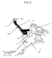
- the body front section runs as a whole with 1 marked frame carrier in the longitudinal direction of one Front area of the body front in the X direction in an arc up to an extension not described in detail the frame structure below the floor one Passenger cell not shown.
- the frame carrier 1 forms a cranked Area 1a off.
- the frame support 1 also includes a integrally molded profile part 2, which is a Part of the lateral surface of a dome-shaped Strut mount 3 extends.
- the body front is made from a side Wheel arch cover 4, which depending on the specific Embodiment designed with stiffening devices is limited and is opposite to the passenger compartment one transverse to the longitudinal direction of the frame support 1 extending end wall 5 completed.
- the end wall 5 comprises an upper area 5a, which is essentially the dashboard area of the passenger compartment to the body front ends and one lower area 5b, behind which the pedal area of the Passenger cell is arranged.
- the upper end wall area 5a extends in the present exemplary embodiment up to one that receives the windshield from below Profile beam 6.
- In the area of the passenger compartment also closes at the rear end of the wheel house 4 an A-pillar 7.
- the space between the frame support 1 and the upper end wall region 5a is highlighted in color for better identification Strut 10 bridges.
- the strut 10 is in conveniently from a material, especially metal manufactured with high rigidity and shaped like a sheet.
- the pressure strut 10 can also consist of one Plastic with sufficient rigidity and / or as Cast part to be made.
- the pressure strut 10 lies to support the Expediently frame at the highest point of the frame support 1, which forms the so-called frame head, with correspondingly shaped support ends 11 and 12.
- the pressure strut 10 has one on the support ends 11 and 12 essentially adjoining large-area trained Pressure receiving area 13, the at least partially a portion of the upper end wall area 5a completely covered.
- the strut 10 stiffened and / or thus twice by means of the pressure receiving area 13 upper end wall area 5a and consequently stiffens this out.
- the Pressure receiving area 13 a recess 14 for receiving one provided in this area of the front body structure Aggregates, with an additional horizontal Transitional area between the pressure receiving area 13 and the support ends 11 and 12 designed to hold the unit is.
- the pressure strut 10 essentially has one through the pressure receiving area 13 and the support end 11 slightly defined V-shaped structure and is essentially tangential to the frame installation direction of movement in follow essentially a frontal crash initiated force, d. H. when swinging up the frame support 1 by one indicated in the cranked area 1a at 8 Swivel axis, arranged.
- the strut 10 is as for those skilled in the art visible in this area, quickly and easily between the frame support 1 and the end wall 5 mountable or can also be retrofitted. In addition to the usual fixatives, such as means for screwing, locking or gluing, no complex connecting elements needed to assemble the strut 1.
- FIG. 4 encompasses the strut 10 with its support ends 11 and 12 at least partially the cathedral 3, so that the Dom 3 itself and the front wheel installation additionally stabilized is and a load introduced therein to the rear can be forwarded.
- the support end 12 is angled towards the support end 11 in a bulkhead shape, see above that a more effective gripping of the strut mount 3 and better support compared to the profile part 2 the frame support 1 is guaranteed.
- Another one given package situation in the motor vehicle could Pressure strut 10 also between the profile part 2 and the Front wall 5 may be arranged.
- the pressure strut 10 thus acts as a direct counter bearing for a frame carrier 1 or of the frame head. Otherwise in the case of bracing in the cranked area of the transition area 1a due to the lever arm between the frame head and the transition area Conditional torque or bending moment therefore only has to intercepted to a significantly reduced extent become.
- the pressure strut 10 has for further stiffening also longitudinal ribs 15 and in the pressure receiving area 13 Stiffening folds 16.
- the strut according to the invention is thus a highly effective component, which depending on the specific bodywork with sufficiently high rigidity is the easiest way to produce.
- the invention also includes embodiments where the strut 10 is essentially one includes straight, I-shaped cross-section and / or that Supporting end 11 is attached directly to the spring dome 3.
Landscapes
- Engineering & Computer Science (AREA)
- Chemical & Material Sciences (AREA)
- Combustion & Propulsion (AREA)
- Transportation (AREA)
- Mechanical Engineering (AREA)
- Body Structure For Vehicles (AREA)
Applications Claiming Priority (2)
| Application Number | Priority Date | Filing Date | Title |
|---|---|---|---|
| DE20103379U DE20103379U1 (de) | 2001-02-26 | 2001-02-26 | Karosserievorderbau eines Kraftfahrzeuges |
| DE20103379U | 2001-02-26 |
Publications (3)
| Publication Number | Publication Date |
|---|---|
| EP1234751A2 true EP1234751A2 (fr) | 2002-08-28 |
| EP1234751A3 EP1234751A3 (fr) | 2004-06-02 |
| EP1234751B1 EP1234751B1 (fr) | 2008-11-05 |
Family
ID=7953555
Family Applications (1)
| Application Number | Title | Priority Date | Filing Date |
|---|---|---|---|
| EP02003184A Expired - Lifetime EP1234751B1 (fr) | 2001-02-26 | 2002-02-18 | Structure avant pour un véhicule automobile |
Country Status (3)
| Country | Link |
|---|---|
| EP (1) | EP1234751B1 (fr) |
| BR (1) | BR0200529A (fr) |
| DE (2) | DE20103379U1 (fr) |
Cited By (6)
| Publication number | Priority date | Publication date | Assignee | Title |
|---|---|---|---|---|
| DE102006008667A1 (de) * | 2006-02-24 | 2007-09-06 | Audi Ag | Domstrebe zur Aussteifung einer selbsttragenden Karosserie eines Kraftwagens |
| EP2014540A1 (fr) * | 2007-07-11 | 2009-01-14 | Peugeot Citroen Automobiles SA | Structure d'une partie avant de la caisse d'un véhicule automobile |
| DE102005050951B4 (de) * | 2005-10-25 | 2014-01-02 | Audi Ag | Fronttragstruktur für ein Kraftfahrzeug |
| FR3031337A1 (fr) * | 2015-01-07 | 2016-07-08 | Peugeot Citroen Automobiles Sa | Element de structure comportant un premier element de renfort sur lequel est solidarise un second element de renfort et vehicule comportant un tel element de structure |
| WO2024252078A1 (fr) * | 2023-06-07 | 2024-12-12 | Stellantis Auto Sas | Ensemble de véhicule automobile et véhicule automobile comportant un tel ensemble |
| DE102023123429A1 (de) * | 2023-08-31 | 2025-03-06 | Bayerische Motoren Werke Aktiengesellschaft | Kraftwagenkarosserie mit einem Vorderwagen mit verstärkter Abstützung der Federbeinaufnahmen |
Families Citing this family (7)
| Publication number | Priority date | Publication date | Assignee | Title |
|---|---|---|---|---|
| DE102009034907A1 (de) * | 2009-07-28 | 2011-02-03 | GM Global Technology Operations, Inc., Detroit | Kraftfahrzeug-Vorderbau, Verwendung eines Strukturbauteils zum Einbau in einem Kraftfahrzeug-Vorderbau und Verfahren zum Einbau eines Strukturbauteils in einem Kraftfahrzeug-Vorderbau |
| DE102010011320A1 (de) | 2010-03-13 | 2011-09-15 | Volkswagen Ag | Vorderwagen eines Fahrzeugs |
| DE102010022158B4 (de) | 2010-05-20 | 2023-03-23 | Volkswagen Ag | Vorderwagenstruktur einer Fahrzeugkarosserie |
| DE102013214763A1 (de) * | 2013-07-29 | 2015-01-29 | Bayerische Motoren Werke Aktiengesellschaft | Karosserie eines Fahrzeugs mit einem Radhaus |
| FR3010966B1 (fr) * | 2013-09-23 | 2017-09-08 | Peugeot Citroen Automobiles Sa | Renfort d'auvent pour ameliorer l'aptitude d'un vehicule automobile a absorber l'energie d'un choc frontal |
| FR3014374B1 (fr) * | 2013-12-05 | 2016-02-05 | Peugeot Citroen Automobiles Sa | Element de renfort pour compartiment moteur de vehicule automobile |
| JP7024434B2 (ja) * | 2018-01-22 | 2022-02-24 | トヨタ自動車株式会社 | カウルブラケット |
Citations (3)
| Publication number | Priority date | Publication date | Assignee | Title |
|---|---|---|---|---|
| DE4209879A1 (de) | 1991-03-28 | 1992-10-01 | Mazda Motor | Vordere karosseriestruktur eines fahrzeugs |
| DE4304920A1 (en) | 1992-03-02 | 1993-09-09 | Volkswagen Ag | Fore carriage for road vehicle - has on each side one-armed longitudinal bearer with downwardly angled area beneath cross wall |
| DE19727615A1 (de) | 1996-08-14 | 1999-02-04 | Opel Adam Ag | Karosserievorderbau für ein Kraftfahrzeug |
Family Cites Families (4)
| Publication number | Priority date | Publication date | Assignee | Title |
|---|---|---|---|---|
| US2228107A (en) * | 1938-09-12 | 1941-01-07 | Packard Motor Car Co | Motor vehicle |
| GB670891A (en) * | 1949-05-10 | 1952-04-30 | Budd Co | Improvements in motor vehicles |
| US2662794A (en) * | 1950-06-08 | 1953-12-15 | Budd Co | Final connection between preassembled units of self-supporting automobile bodies |
| JPS59190060A (ja) * | 1983-04-13 | 1984-10-27 | Honda Motor Co Ltd | 自動車の車体 |
-
2001
- 2001-02-26 DE DE20103379U patent/DE20103379U1/de not_active Expired - Lifetime
-
2002
- 2002-02-18 EP EP02003184A patent/EP1234751B1/fr not_active Expired - Lifetime
- 2002-02-18 DE DE50212973T patent/DE50212973D1/de not_active Expired - Lifetime
- 2002-02-26 BR BR0200529A patent/BR0200529A/pt not_active IP Right Cessation
Patent Citations (3)
| Publication number | Priority date | Publication date | Assignee | Title |
|---|---|---|---|---|
| DE4209879A1 (de) | 1991-03-28 | 1992-10-01 | Mazda Motor | Vordere karosseriestruktur eines fahrzeugs |
| DE4304920A1 (en) | 1992-03-02 | 1993-09-09 | Volkswagen Ag | Fore carriage for road vehicle - has on each side one-armed longitudinal bearer with downwardly angled area beneath cross wall |
| DE19727615A1 (de) | 1996-08-14 | 1999-02-04 | Opel Adam Ag | Karosserievorderbau für ein Kraftfahrzeug |
Cited By (8)
| Publication number | Priority date | Publication date | Assignee | Title |
|---|---|---|---|---|
| DE102005050951B4 (de) * | 2005-10-25 | 2014-01-02 | Audi Ag | Fronttragstruktur für ein Kraftfahrzeug |
| DE102006008667A1 (de) * | 2006-02-24 | 2007-09-06 | Audi Ag | Domstrebe zur Aussteifung einer selbsttragenden Karosserie eines Kraftwagens |
| EP2014540A1 (fr) * | 2007-07-11 | 2009-01-14 | Peugeot Citroen Automobiles SA | Structure d'une partie avant de la caisse d'un véhicule automobile |
| FR2918630A1 (fr) * | 2007-07-11 | 2009-01-16 | Peugeot Citroen Automobiles Sa | Structure d'une partie avant de la caisse d'un vehicule automobile. |
| FR3031337A1 (fr) * | 2015-01-07 | 2016-07-08 | Peugeot Citroen Automobiles Sa | Element de structure comportant un premier element de renfort sur lequel est solidarise un second element de renfort et vehicule comportant un tel element de structure |
| WO2024252078A1 (fr) * | 2023-06-07 | 2024-12-12 | Stellantis Auto Sas | Ensemble de véhicule automobile et véhicule automobile comportant un tel ensemble |
| FR3149579A1 (fr) * | 2023-06-07 | 2024-12-13 | Psa Automobiles Sa | Ensemble de véhicule automobile et véhicule automobile comportant un tel ensemble |
| DE102023123429A1 (de) * | 2023-08-31 | 2025-03-06 | Bayerische Motoren Werke Aktiengesellschaft | Kraftwagenkarosserie mit einem Vorderwagen mit verstärkter Abstützung der Federbeinaufnahmen |
Also Published As
| Publication number | Publication date |
|---|---|
| EP1234751B1 (fr) | 2008-11-05 |
| DE20103379U1 (de) | 2001-06-13 |
| EP1234751A3 (fr) | 2004-06-02 |
| BR0200529A (pt) | 2002-10-08 |
| DE50212973D1 (de) | 2008-12-18 |
Similar Documents
| Publication | Publication Date | Title |
|---|---|---|
| DE69805388T2 (de) | Ausbildung des vorderen Längsträgers eines Kraftfahrzeuges | |
| DE19748970B4 (de) | Integrale Türinnenverstärkung | |
| EP1840003A2 (fr) | Elément de renforcement d'un soubassement de porte de carrosserie de véhicule automobile | |
| WO2004009428A1 (fr) | Ensemble de support de sol pour automobile | |
| EP1073579A1 (fr) | Coque d'un vehicule automobile | |
| EP1059220A2 (fr) | Structure de carrosserie autoporteuse d'un véhicule automobile | |
| EP1925530A1 (fr) | Véhicule automobile avec traverses frontales | |
| EP1532040A1 (fr) | Carrosserie de voiture a structure portante composee de modules de grandes dimensions | |
| EP1234751B1 (fr) | Structure avant pour un véhicule automobile | |
| DE19839521C1 (de) | Vorbaustruktur für ein Kraftfahrzeug | |
| EP0989052B1 (fr) | Renforcement pour carosserie auto-porteuse d'un véhicule | |
| EP1000840A2 (fr) | Structure de suppport de la partie avant pour un véhicule automobile | |
| DE10058113B4 (de) | Hilfsrahmenmodul | |
| WO2013087141A1 (fr) | Dispositif de protection pour une voiture particulière | |
| DE102009004886B4 (de) | Aufbaustruktur | |
| EP1090818B1 (fr) | Véhicule à moteur équipé avec un extrémité frontale aimable de piétons | |
| DE112006000425B4 (de) | Fahrzeugendabschnittsstruktur | |
| DE19858303B4 (de) | Vorbaustruktur für eine selbsttragende Rohbaukarosserie eines Personenkraftwagens | |
| DE2619173A1 (de) | Als geschlossener hohltraeger ausgebildeter vorderer laengstraeger | |
| EP2657111A2 (fr) | Suspension de cabine | |
| DE19853338B4 (de) | Anordnung mit einer Frontsäule für einen Karosserierahmen eines Kraftfahrzeugs | |
| DE102004050435A1 (de) | Stoßfängersystem für Kraftfahrzeug | |
| DE102018009196B3 (de) | Vorbaustrukturanordnung für einen Kraftwagenrohbau | |
| DE10032663B4 (de) | Kraftwagen mit einer selbsttragenden Karosserie | |
| DE4304920B4 (de) | Vorderwagen für ein Kraftfahrzeug |
Legal Events
| Date | Code | Title | Description |
|---|---|---|---|
| PUAI | Public reference made under article 153(3) epc to a published international application that has entered the european phase |
Free format text: ORIGINAL CODE: 0009012 |
|
| AK | Designated contracting states |
Kind code of ref document: A2 Designated state(s): AT BE CH CY DE DK ES FI FR GB GR IE IT LI LU MC NL PT SE TR |
|
| AX | Request for extension of the european patent |
Free format text: AL;LT;LV;MK;RO;SI |
|
| PUAL | Search report despatched |
Free format text: ORIGINAL CODE: 0009013 |
|
| AK | Designated contracting states |
Kind code of ref document: A3 Designated state(s): AT BE CH CY DE DK ES FI FR GB GR IE IT LI LU MC NL PT SE TR |
|
| AX | Request for extension of the european patent |
Extension state: AL LT LV MK RO SI |
|
| 17P | Request for examination filed |
Effective date: 20040816 |
|
| AKX | Designation fees paid |
Designated state(s): DE FR GB |
|
| RBV | Designated contracting states (corrected) |
Designated state(s): DE FR GB |
|
| GRAP | Despatch of communication of intention to grant a patent |
Free format text: ORIGINAL CODE: EPIDOSNIGR1 |
|
| GRAS | Grant fee paid |
Free format text: ORIGINAL CODE: EPIDOSNIGR3 |
|
| GRAA | (expected) grant |
Free format text: ORIGINAL CODE: 0009210 |
|
| AK | Designated contracting states |
Kind code of ref document: B1 Designated state(s): DE FR GB |
|
| REG | Reference to a national code |
Ref country code: GB Ref legal event code: FG4D Free format text: NOT ENGLISH |
|
| REF | Corresponds to: |
Ref document number: 50212973 Country of ref document: DE Date of ref document: 20081218 Kind code of ref document: P |
|
| RAP2 | Party data changed (patent owner data changed or rights of a patent transferred) |
Owner name: GM GLOBAL TECHNOLOGY OPERATIONS, INC. |
|
| REG | Reference to a national code |
Ref country code: GB Ref legal event code: 732E Free format text: REGISTERED BETWEEN 20090219 AND 20090225 |
|
| REG | Reference to a national code |
Ref country code: GB Ref legal event code: 732E Free format text: REGISTERED BETWEEN 20090305 AND 20090311 |
|
| PLBE | No opposition filed within time limit |
Free format text: ORIGINAL CODE: 0009261 |
|
| STAA | Information on the status of an ep patent application or granted ep patent |
Free format text: STATUS: NO OPPOSITION FILED WITHIN TIME LIMIT |
|
| 26N | No opposition filed |
Effective date: 20090806 |
|
| REG | Reference to a national code |
Ref country code: GB Ref legal event code: 732E Free format text: REGISTERED BETWEEN 20091029 AND 20091104 |
|
| REG | Reference to a national code |
Ref country code: GB Ref legal event code: 732E Free format text: REGISTERED BETWEEN 20091105 AND 20091111 |
|
| REG | Reference to a national code |
Ref country code: FR Ref legal event code: CD Ref country code: FR Ref legal event code: TP Ref country code: FR Ref legal event code: CJ |
|
| REG | Reference to a national code |
Ref country code: DE Ref legal event code: R081 Ref document number: 50212973 Country of ref document: DE Owner name: GM GLOBAL TECHNOLOGY OPERATIONS LLC (N. D. GES, US Free format text: FORMER OWNER: GM GLOBAL TECHNOLOGY OPERATIONS, INC., DETROIT, MICH., US Effective date: 20110323 Ref country code: DE Ref legal event code: R081 Ref document number: 50212973 Country of ref document: DE Owner name: GM GLOBAL TECHNOLOGY OPERATIONS LLC (N. D. GES, US Free format text: FORMER OWNER: GM GLOBAL TECHNOLOGY OPERATIONS, INC., DETROIT, US Effective date: 20110323 |
|
| REG | Reference to a national code |
Ref country code: FR Ref legal event code: PLFP Year of fee payment: 15 |
|
| REG | Reference to a national code |
Ref country code: FR Ref legal event code: PLFP Year of fee payment: 16 |
|
| PGFP | Annual fee paid to national office [announced via postgrant information from national office to epo] |
Ref country code: FR Payment date: 20170112 Year of fee payment: 16 Ref country code: DE Payment date: 20170214 Year of fee payment: 16 |
|
| PGFP | Annual fee paid to national office [announced via postgrant information from national office to epo] |
Ref country code: GB Payment date: 20170215 Year of fee payment: 16 |
|
| REG | Reference to a national code |
Ref country code: DE Ref legal event code: R119 Ref document number: 50212973 Country of ref document: DE |
|
| GBPC | Gb: european patent ceased through non-payment of renewal fee |
Effective date: 20180218 |
|
| REG | Reference to a national code |
Ref country code: FR Ref legal event code: ST Effective date: 20181031 |
|
| PG25 | Lapsed in a contracting state [announced via postgrant information from national office to epo] |
Ref country code: DE Free format text: LAPSE BECAUSE OF NON-PAYMENT OF DUE FEES Effective date: 20180901 |
|
| PG25 | Lapsed in a contracting state [announced via postgrant information from national office to epo] |
Ref country code: GB Free format text: LAPSE BECAUSE OF NON-PAYMENT OF DUE FEES Effective date: 20180218 Ref country code: FR Free format text: LAPSE BECAUSE OF NON-PAYMENT OF DUE FEES Effective date: 20180228 |