EP1234764A2 - Dispositif de suppression d'infrarouges pour aéronef - Google Patents
Dispositif de suppression d'infrarouges pour aéronef Download PDFInfo
- Publication number
- EP1234764A2 EP1234764A2 EP02002742A EP02002742A EP1234764A2 EP 1234764 A2 EP1234764 A2 EP 1234764A2 EP 02002742 A EP02002742 A EP 02002742A EP 02002742 A EP02002742 A EP 02002742A EP 1234764 A2 EP1234764 A2 EP 1234764A2
- Authority
- EP
- European Patent Office
- Prior art keywords
- gas
- pressure tank
- liquid
- piston
- space
- Prior art date
- Legal status (The legal status is an assumption and is not a legal conclusion. Google has not performed a legal analysis and makes no representation as to the accuracy of the status listed.)
- Granted
Links
- 239000007788 liquid Substances 0.000 claims abstract description 30
- 239000000110 cooling liquid Substances 0.000 claims abstract description 12
- 239000004449 solid propellant Substances 0.000 claims abstract description 8
- 239000003350 kerosene Substances 0.000 claims abstract description 4
- 239000002826 coolant Substances 0.000 claims description 23
- 239000000446 fuel Substances 0.000 claims description 11
- 238000010438 heat treatment Methods 0.000 claims description 4
- 238000002347 injection Methods 0.000 claims description 2
- 239000007924 injection Substances 0.000 claims description 2
- 238000005496 tempering Methods 0.000 claims 1
- 238000005507 spraying Methods 0.000 abstract 1
- 238000000034 method Methods 0.000 description 4
- 241000383403 Solen Species 0.000 description 3
- 230000005855 radiation Effects 0.000 description 3
- 238000000889 atomisation Methods 0.000 description 2
- 230000009172 bursting Effects 0.000 description 2
- 238000007710 freezing Methods 0.000 description 2
- 230000008014 freezing Effects 0.000 description 2
- 238000001816 cooling Methods 0.000 description 1
- 230000001419 dependent effect Effects 0.000 description 1
- 230000000694 effects Effects 0.000 description 1
- 238000005429 filling process Methods 0.000 description 1
- 239000002828 fuel tank Substances 0.000 description 1
Images
Classifications
-
- B—PERFORMING OPERATIONS; TRANSPORTING
- B64—AIRCRAFT; AVIATION; COSMONAUTICS
- B64D—EQUIPMENT FOR FITTING IN OR TO AIRCRAFT; FLIGHT SUITS; PARACHUTES; ARRANGEMENT OR MOUNTING OF POWER PLANTS OR PROPULSION TRANSMISSIONS IN AIRCRAFT
- B64D33/00—Arrangement in aircraft of power plant parts or auxiliaries not otherwise provided for
- B64D33/04—Arrangement in aircraft of power plant parts or auxiliaries not otherwise provided for of exhaust outlets or jet pipes
-
- F—MECHANICAL ENGINEERING; LIGHTING; HEATING; WEAPONS; BLASTING
- F02—COMBUSTION ENGINES; HOT-GAS OR COMBUSTION-PRODUCT ENGINE PLANTS
- F02K—JET-PROPULSION PLANTS
- F02K1/00—Plants characterised by the form or arrangement of the jet pipe or nozzle; Jet pipes or nozzles peculiar thereto
- F02K1/78—Other construction of jet pipes
- F02K1/82—Jet pipe walls, e.g. liners
- F02K1/822—Heat insulating structures or liners, cooling arrangements, e.g. post combustion liners; Infrared radiation suppressors
- F02K1/825—Infrared radiation suppressors
Definitions
- the invention relates to a device for reducing the IR target signature of Aircraft according to the preamble of claim 1.
- Guided missiles with an IR seeker head are a threat to aircraft because they are involved their unavoidable IR radiation is a good target signature for the IR seeker represent the guided missile.
- Aircraft can emit IR flares that identify the threat pull yourself and thus distract from the real goal.
- Guided missiles are, however, intended for the case of such a countermeasure Logics are provided that consist of the search head being recognized the emission of a pseudo target that recognizes as the real target the most effective approximates the IR radiation of the target before the false target also in the The missile's seeker head appeared. This logic module in the search head ensures for IR sham targets to become ineffective as long as the real target is additional does not abruptly change your own IR radiation to emit a false target.
- DE 197 21 429 A1 describes such a method and an apparatus known to carry out the method. This creates a coolant by means of a device comprising a tank, a high pressure pump and a line and nozzle system, sprayed into the exhaust gas jet of the aircraft.
- the disadvantage is that it is not possible with conventional high pressure pumps within of fractions of a second, typically less than 1/10 of a second for one fine atomization and the pressure required for the required high throughput quantities build.
- the object of the invention is to provide a device with which it is possible the pressure required for a fine atomization of the coolant in the exhaust gas and the Build up the required throughput in fractions of a second.
- the device comprises a high pressure tank with an in Piston located inside this tank, the interior of the high pressure tank divided into a gas space and a liquid space and between two end stops, in particular a gas chamber side stop and a liquid chamber side Stop, is movable, a pump for filling the high pressure tank with the coolant, one or more gas generators with solid fuel, which in the Gas space arranged or connected to the gas space, after ignition of the solid fuel, the gas escaping from the gas generator in the piston High pressure tank moves, a nozzle system, by means of which the liquid flows directly into the exhaust gas is sprayed and a pipe or hose system for distribution the coolant to the nozzle system.
- the pipeline and hose system is in an advantageous embodiment of the invention through an opening on the high-pressure tank between the two end stops of the movable piston is connected to the high pressure tank.
- This The opening is conveniently located in front of the liquid chamber-side stop Distance sufficient that the entire movable piston over this Opening can move away.
- an unpressurized tank is for Coolant supply available.
- the unpressurized tank is with the Pump connected to fill the high pressure tank.
- the high pressure tank by means of the piston movable inside two separate cavities, in particular a gas and a liquid space educated.
- the liquid space of the high pressure tank is by means of the pump and the pressureless storage tank connected to it can be filled with the coolant.
- the piston moves freely up to the gas chamber side stop, the gas chamber accordingly the amount of coolant filled is reduced.
- a gas vent valve is provided in the gas space, which is used when filling the liquid space is opened to build up pressure in the gas space due to the reduction in volume to avoid.
- the Gas chamber connected gas generator ignited with solid fuel.
- the gas generator According to the invention, this is either within the gas space of the high-pressure tank arranged or with lines, in particular pressure-resistant lines, with connected to the gas space.
- Another advantage is that immediately after igniting the gas generator and bursting the Rupture disc the appropriate pressure is present and due to the coolant the movement of the piston without loss of pressure in the pipeline or Hose system can be directed. It is therefore not a pump to build the Pressure needed. Thus, there is none in the device according to the invention Delay in pressure build-up.
- the nozzle system is in the afterburner area arranged of the aircraft. So it is possible in the coolant Inject the afterburner chamber into the exhaust gas.
- the pipeline or Hose system connected to the afterburner fuel supply system.
- This connection of the pipeline or hose system to the fuel supply system is advantageously carried out via a three-way valve. It is therefore possible that the Coolant directly into the afterburner via the fuel lines of the afterburner arrives and is atomized there, as is usually the case with fuel normal afterburner operation takes place.
- An electrical heating system with sensor-controlled regulation enables in one a further advantageous embodiment of the invention a temperature control of the cooling liquid. This prevents the coolant in the storage tank, in the high pressure tank or freezes in the pipes.
- the performance of the electrical heating system depending on the use of the coolant. So is with the use of e.g. Solen as a cooling liquid requires a low heating output because Solen has a very low freezing point due to the effect of lowering the freezing point exhibit.
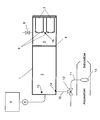
- the only drawing shows a high-pressure tank 1, which is connected to a pump 5 with a Storage tank 6 is connected to coolant. Inside the high pressure tank 1 there is a movable piston 4, which in the interior of the high pressure tank 1 divides a liquid space 2 and a gas space 3. The piston 4 is between a stop 15 on the liquid chamber side and a stop 16 on the gas chamber side movable.
- Gas generators 7 with solid fuel are located in the gas space 3. It is also possible that the gas generators 7 are arranged outside the high-pressure tank 1 are and connected to the gas space 3 via a line system, not shown are. The openings of the gas generators 7 are closed by means of a rupture disk 8. In addition, a vent valve 9 is connected to the gas space 3, which is opened when filling the liquid space 2 and after the liquid space 2 has been completely filled - the piston 4 is located on the gas chamber side Stop 16 - is closed.
- the liquid space 2 is connected via a pipeline or hose system 10 with a arranged in the fuel line 11 of the aircraft arranged three-way valve 12.
- the pipeline or hose system 10 is connected via an opening 14 connected to the high pressure tank 1. This opening 14 is in sufficient Distance in front of the liquid chamber side stop 15, so that the piston 4 can be moved completely over this opening 14.
- the coolant When filling the liquid space 2, the coolant is released from the unpressurized Storage tank 6 pressed into the high-pressure tank 1 via the pump 5.
- the movable piston 4 displaced in the direction of the gas chamber side stop 16.
- the gas located in the gas space 3 escapes through the open vent valve 9, so that no pressure can be built up in the gas space 3.
- the vent valve 9 closed.
- the three-way valve 12 is in the process of filling switched such that the cooling liquid does not enter the fuel line 11 of the afterburner can flow, i.e. normal afterburner operation is possible.
- the piston 4 moves through the opening when emptying the liquid space 2 14 away.
- the gas space 3 of the high pressure tank 1 through the opening 14 with the Pipe or hose system 10 connected. That in the gas space 2 under pressure standing gas now escapes through the opening 14 into the pipeline or Hose system 10 and through the three-way valve 12 into the fuel line 11 of the Afterburner.
- the gas space 2 is depressurized.
- the three-way valve 12 is switched over to refill the high-pressure tank 1. Normal afterburner operation is possible again.
Landscapes
- Engineering & Computer Science (AREA)
- Chemical & Material Sciences (AREA)
- Combustion & Propulsion (AREA)
- Mechanical Engineering (AREA)
- General Engineering & Computer Science (AREA)
- Aviation & Aerospace Engineering (AREA)
- Filling Or Discharging Of Gas Storage Vessels (AREA)
- Aiming, Guidance, Guns With A Light Source, Armor, Camouflage, And Targets (AREA)
- Radar Systems Or Details Thereof (AREA)
Applications Claiming Priority (2)
| Application Number | Priority Date | Filing Date | Title |
|---|---|---|---|
| DE10109274A DE10109274A1 (de) | 2001-02-24 | 2001-02-24 | Vorrichtung zur Verminderung der IR-Zielsignatur von Luftfahrzeugen |
| DE10109274 | 2001-02-24 |
Publications (3)
| Publication Number | Publication Date |
|---|---|
| EP1234764A2 true EP1234764A2 (fr) | 2002-08-28 |
| EP1234764A3 EP1234764A3 (fr) | 2003-06-04 |
| EP1234764B1 EP1234764B1 (fr) | 2004-07-14 |
Family
ID=7675570
Family Applications (1)
| Application Number | Title | Priority Date | Filing Date |
|---|---|---|---|
| EP02002742A Expired - Lifetime EP1234764B1 (fr) | 2001-02-24 | 2002-02-07 | Dispositif de suppression d'infrarouges pour aéronef |
Country Status (4)
| Country | Link |
|---|---|
| EP (1) | EP1234764B1 (fr) |
| AT (1) | ATE271001T1 (fr) |
| DE (2) | DE10109274A1 (fr) |
| ES (1) | ES2222409T3 (fr) |
Citations (1)
| Publication number | Priority date | Publication date | Assignee | Title |
|---|---|---|---|---|
| DE19721429A1 (de) | 1997-05-22 | 1998-11-26 | Dornier Gmbh | Verminderung der Zielsignatur von Luftfahrzeugen |
Family Cites Families (8)
| Publication number | Priority date | Publication date | Assignee | Title |
|---|---|---|---|---|
| US3901035A (en) * | 1972-10-20 | 1975-08-26 | Tokico Ltd | Hydraulic pressure generating apparatus for use in an emergency |
| US3897173A (en) * | 1973-03-22 | 1975-07-29 | Harold Mandroian | Electrolysis pump |
| DE2961362D1 (en) * | 1978-09-18 | 1982-01-21 | Sperry Ltd | Fluid supply systems |
| US4303035A (en) * | 1979-04-03 | 1981-12-01 | The United States Of America As Represented By The Secretary Of The Navy | Method of suppressing radiation from ship stack gases |
| US5269132A (en) * | 1992-10-29 | 1993-12-14 | E-Systems, Inc. | Method and apparatus for controlling infrared emissions |
| DE19619376A1 (de) * | 1996-05-14 | 1997-11-20 | Winsel August | Verfahren und Vorrichtung zur gesteuerten oder geregelten Förderung von fließfähigen Medien mit einer Gasentwicklungszelle und einem Strömungsvervielfacher |
| RU2109168C1 (ru) * | 1996-12-14 | 1998-04-20 | Общество с ограниченной ответственностью Творческое производственное объединение "Резерв" | Объемная гидромашина |
| DE19842763B4 (de) * | 1997-05-22 | 2005-05-04 | Eads Deutschland Gmbh | Verminderung der Zielsignatur von Luftfahrzeugen |
-
2001
- 2001-02-24 DE DE10109274A patent/DE10109274A1/de not_active Withdrawn
-
2002
- 2002-02-07 AT AT02002742T patent/ATE271001T1/de not_active IP Right Cessation
- 2002-02-07 EP EP02002742A patent/EP1234764B1/fr not_active Expired - Lifetime
- 2002-02-07 DE DE50200607T patent/DE50200607D1/de not_active Expired - Lifetime
- 2002-02-07 ES ES02002742T patent/ES2222409T3/es not_active Expired - Lifetime
Patent Citations (1)
| Publication number | Priority date | Publication date | Assignee | Title |
|---|---|---|---|---|
| DE19721429A1 (de) | 1997-05-22 | 1998-11-26 | Dornier Gmbh | Verminderung der Zielsignatur von Luftfahrzeugen |
Also Published As
| Publication number | Publication date |
|---|---|
| ATE271001T1 (de) | 2004-07-15 |
| ES2222409T3 (es) | 2005-02-01 |
| DE50200607D1 (de) | 2004-08-19 |
| DE10109274A1 (de) | 2002-09-26 |
| EP1234764A3 (fr) | 2003-06-04 |
| EP1234764B1 (fr) | 2004-07-14 |
Similar Documents
| Publication | Publication Date | Title |
|---|---|---|
| DE69421295T2 (de) | Gaskartousche | |
| DE19903664C2 (de) | Einrichtung zur Treibstoffzufuhr für ein Raketentriebwerk und Wärmetauscher zur Verwendung in der Einrichtung | |
| CH653436A5 (de) | Geschuetz fuer den antrieb durch fluessigen treibstoff. | |
| DE1291207B (de) | Ablenkeinrichtung fuer den Schubstrahl einer Rueckstossduese eines Luft- oder Raumfahrzeuges | |
| DE3728533C2 (fr) | ||
| US3240432A (en) | Apparatus for spraying resin | |
| EP2076707B1 (fr) | Dispositif pour le remplissage rapide de récipients de gaz sous pression | |
| EP3189296B1 (fr) | Tube d'éjection pour sous-marin | |
| DE69109797T2 (de) | Zirkulationssystem für einen kontinuierlichen Brennstoffstrom. | |
| EP0078893B1 (fr) | Projectile guidé | |
| EP1234764B1 (fr) | Dispositif de suppression d'infrarouges pour aéronef | |
| DE1802275B1 (de) | Druckhalte- und Drainageventil eines Gasturbinentriebwerkes | |
| DE2846372C2 (de) | Geschoß mit radialgerichteten Steuerdüsen zur Endphasenlenkung | |
| EP2285454B1 (fr) | Dispositif et procédé d'éjection pulsée de fluide | |
| DE19743789B4 (de) | Vorrichtung zum stoßartigen Ausblasen von Druckluft zur Beseitigung von Materialanbackungen von Schüttgütern in Reaktionsbehältern | |
| EP1528013B1 (fr) | Dispositif aérateur de décolmatage avec ventil placé dans la partie superieure de l'interieur d'un conteneur | |
| EP0823968A1 (fr) | Alimentation en gaz sous haute pression | |
| DE4022542C2 (de) | Sprühvorrichtung zum Kühlen des Ladungsraums im Bereich der maximalen Ladungsraumtemperatur | |
| DE19842542A1 (de) | Kühlvorrichtung zur verschlußseitigen Zuführung eines Kühlmediums | |
| DE19743791A1 (de) | Rohrwaffe | |
| EP0993322B1 (fr) | Dispositif d'extinction impulsionnel | |
| DE10137711A1 (de) | Verfahren zum Beschichten von Flächen mit einem Mehrkomponentenkunststoffgemisch und Anlage | |
| WO2023274783A1 (fr) | Dispositif de compensation d'arme à faible bruit dans un sous-marin, et procédé de fonctionnement | |
| EP1477231B1 (fr) | Dispositif pour la préservation des espaces creux | |
| DE1576833A1 (de) | Vorrichtung zum Einfuehren einer kontrollierten Kuehlwassermenge in eine Leitung fuer ueberhitzten Dampf |
Legal Events
| Date | Code | Title | Description |
|---|---|---|---|
| PUAI | Public reference made under article 153(3) epc to a published international application that has entered the european phase |
Free format text: ORIGINAL CODE: 0009012 |
|
| AK | Designated contracting states |
Kind code of ref document: A2 Designated state(s): AT BE CH CY DE DK ES FI FR GB GR IE IT LI LU MC NL PT SE TR |
|
| AX | Request for extension of the european patent |
Free format text: AL;LT;LV;MK;RO;SI |
|
| PUAL | Search report despatched |
Free format text: ORIGINAL CODE: 0009013 |
|
| AK | Designated contracting states |
Designated state(s): AT BE CH CY DE DK ES FI FR GB GR IE IT LI LU MC NL PT SE TR |
|
| AX | Request for extension of the european patent |
Extension state: AL LT LV MK RO SI |
|
| 17P | Request for examination filed |
Effective date: 20030703 |
|
| 17Q | First examination report despatched |
Effective date: 20030902 |
|
| GRAP | Despatch of communication of intention to grant a patent |
Free format text: ORIGINAL CODE: EPIDOSNIGR1 |
|
| AKX | Designation fees paid |
Designated state(s): AT BE CH CY DE DK ES FI FR GB GR IE IT LI LU MC NL PT SE TR |
|
| GRAS | Grant fee paid |
Free format text: ORIGINAL CODE: EPIDOSNIGR3 |
|
| GRAA | (expected) grant |
Free format text: ORIGINAL CODE: 0009210 |
|
| AK | Designated contracting states |
Kind code of ref document: B1 Designated state(s): AT BE CH CY DE DK ES FI FR GB GR IE IT LI LU MC NL PT SE TR |
|
| PG25 | Lapsed in a contracting state [announced via postgrant information from national office to epo] |
Ref country code: FI Free format text: LAPSE BECAUSE OF FAILURE TO SUBMIT A TRANSLATION OF THE DESCRIPTION OR TO PAY THE FEE WITHIN THE PRESCRIBED TIME-LIMIT Effective date: 20040714 Ref country code: NL Free format text: LAPSE BECAUSE OF FAILURE TO SUBMIT A TRANSLATION OF THE DESCRIPTION OR TO PAY THE FEE WITHIN THE PRESCRIBED TIME-LIMIT Effective date: 20040714 Ref country code: TR Free format text: LAPSE BECAUSE OF FAILURE TO SUBMIT A TRANSLATION OF THE DESCRIPTION OR TO PAY THE FEE WITHIN THE PRESCRIBED TIME-LIMIT Effective date: 20040714 Ref country code: IE Free format text: LAPSE BECAUSE OF FAILURE TO SUBMIT A TRANSLATION OF THE DESCRIPTION OR TO PAY THE FEE WITHIN THE PRESCRIBED TIME-LIMIT Effective date: 20040714 |
|
| REG | Reference to a national code |
Ref country code: GB Ref legal event code: FG4D Free format text: NOT ENGLISH |
|
| REG | Reference to a national code |
Ref country code: CH Ref legal event code: EP |
|
| RAP2 | Party data changed (patent owner data changed or rights of a patent transferred) |
Owner name: EADS DEUTSCHLAND GMBH |
|
| REF | Corresponds to: |
Ref document number: 50200607 Country of ref document: DE Date of ref document: 20040819 Kind code of ref document: P |
|
| REG | Reference to a national code |
Ref country code: IE Ref legal event code: FG4D Free format text: GERMAN |
|
| NLT2 | Nl: modifications (of names), taken from the european patent patent bulletin |
Owner name: EADS DEUTSCHLAND GMBH |
|
| PG25 | Lapsed in a contracting state [announced via postgrant information from national office to epo] |
Ref country code: DK Free format text: LAPSE BECAUSE OF FAILURE TO SUBMIT A TRANSLATION OF THE DESCRIPTION OR TO PAY THE FEE WITHIN THE PRESCRIBED TIME-LIMIT Effective date: 20041014 Ref country code: GR Free format text: LAPSE BECAUSE OF FAILURE TO SUBMIT A TRANSLATION OF THE DESCRIPTION OR TO PAY THE FEE WITHIN THE PRESCRIBED TIME-LIMIT Effective date: 20041014 Ref country code: SE Free format text: LAPSE BECAUSE OF FAILURE TO SUBMIT A TRANSLATION OF THE DESCRIPTION OR TO PAY THE FEE WITHIN THE PRESCRIBED TIME-LIMIT Effective date: 20041014 |
|
| GBT | Gb: translation of ep patent filed (gb section 77(6)(a)/1977) | ||
| NLV1 | Nl: lapsed or annulled due to failure to fulfill the requirements of art. 29p and 29m of the patents act | ||
| REG | Reference to a national code |
Ref country code: ES Ref legal event code: FG2A Ref document number: 2222409 Country of ref document: ES Kind code of ref document: T3 |
|
| ET | Fr: translation filed | ||
| PG25 | Lapsed in a contracting state [announced via postgrant information from national office to epo] |
Ref country code: CY Free format text: LAPSE BECAUSE OF FAILURE TO SUBMIT A TRANSLATION OF THE DESCRIPTION OR TO PAY THE FEE WITHIN THE PRESCRIBED TIME-LIMIT Effective date: 20050207 Ref country code: AT Free format text: LAPSE BECAUSE OF NON-PAYMENT OF DUE FEES Effective date: 20050207 Ref country code: LU Free format text: LAPSE BECAUSE OF NON-PAYMENT OF DUE FEES Effective date: 20050207 |
|
| PG25 | Lapsed in a contracting state [announced via postgrant information from national office to epo] |
Ref country code: MC Free format text: LAPSE BECAUSE OF NON-PAYMENT OF DUE FEES Effective date: 20050228 Ref country code: BE Free format text: LAPSE BECAUSE OF NON-PAYMENT OF DUE FEES Effective date: 20050228 |
|
| REG | Reference to a national code |
Ref country code: IE Ref legal event code: FD4D |
|
| PLBE | No opposition filed within time limit |
Free format text: ORIGINAL CODE: 0009261 |
|
| STAA | Information on the status of an ep patent application or granted ep patent |
Free format text: STATUS: NO OPPOSITION FILED WITHIN TIME LIMIT |
|
| 26N | No opposition filed |
Effective date: 20050415 |
|
| BERE | Be: lapsed |
Owner name: *DORNIER G.M.B.H. Effective date: 20050228 |
|
| PG25 | Lapsed in a contracting state [announced via postgrant information from national office to epo] |
Ref country code: CH Free format text: LAPSE BECAUSE OF NON-PAYMENT OF DUE FEES Effective date: 20060228 Ref country code: LI Free format text: LAPSE BECAUSE OF NON-PAYMENT OF DUE FEES Effective date: 20060228 |
|
| REG | Reference to a national code |
Ref country code: CH Ref legal event code: PL |
|
| BERE | Be: lapsed |
Owner name: *DORNIER G.M.B.H. Effective date: 20050228 |
|
| PG25 | Lapsed in a contracting state [announced via postgrant information from national office to epo] |
Ref country code: PT Free format text: LAPSE BECAUSE OF NON-PAYMENT OF DUE FEES Effective date: 20041214 |
|
| REG | Reference to a national code |
Ref country code: DE Ref legal event code: R081 Ref document number: 50200607 Country of ref document: DE Owner name: AIRBUS DEFENCE AND SPACE GMBH, DE Free format text: FORMER OWNER: DORNIER GMBH, 88039 FRIEDRICHSHAFEN, DE Effective date: 20140916 |
|
| REG | Reference to a national code |
Ref country code: FR Ref legal event code: PLFP Year of fee payment: 15 |
|
| REG | Reference to a national code |
Ref country code: FR Ref legal event code: PLFP Year of fee payment: 16 |
|
| REG | Reference to a national code |
Ref country code: FR Ref legal event code: PLFP Year of fee payment: 17 |
|
| PGFP | Annual fee paid to national office [announced via postgrant information from national office to epo] |
Ref country code: IT Payment date: 20190225 Year of fee payment: 18 Ref country code: GB Payment date: 20190218 Year of fee payment: 18 Ref country code: ES Payment date: 20190320 Year of fee payment: 18 Ref country code: DE Payment date: 20190219 Year of fee payment: 18 |
|
| PGFP | Annual fee paid to national office [announced via postgrant information from national office to epo] |
Ref country code: FR Payment date: 20190219 Year of fee payment: 18 |
|
| REG | Reference to a national code |
Ref country code: DE Ref legal event code: R119 Ref document number: 50200607 Country of ref document: DE |
|
| GBPC | Gb: european patent ceased through non-payment of renewal fee |
Effective date: 20200207 |
|
| PG25 | Lapsed in a contracting state [announced via postgrant information from national office to epo] |
Ref country code: GB Free format text: LAPSE BECAUSE OF NON-PAYMENT OF DUE FEES Effective date: 20200207 Ref country code: FR Free format text: LAPSE BECAUSE OF NON-PAYMENT OF DUE FEES Effective date: 20200229 Ref country code: DE Free format text: LAPSE BECAUSE OF NON-PAYMENT OF DUE FEES Effective date: 20200901 |
|
| PG25 | Lapsed in a contracting state [announced via postgrant information from national office to epo] |
Ref country code: ES Free format text: LAPSE BECAUSE OF NON-PAYMENT OF DUE FEES Effective date: 20200208 |
|
| PG25 | Lapsed in a contracting state [announced via postgrant information from national office to epo] |
Ref country code: IT Free format text: LAPSE BECAUSE OF NON-PAYMENT OF DUE FEES Effective date: 20200207 |