EP1234806B1 - Verfahren zur Herstellung einer optischen Faser - Google Patents
Verfahren zur Herstellung einer optischen Faser Download PDFInfo
- Publication number
- EP1234806B1 EP1234806B1 EP02003258A EP02003258A EP1234806B1 EP 1234806 B1 EP1234806 B1 EP 1234806B1 EP 02003258 A EP02003258 A EP 02003258A EP 02003258 A EP02003258 A EP 02003258A EP 1234806 B1 EP1234806 B1 EP 1234806B1
- Authority
- EP
- European Patent Office
- Prior art keywords
- holes
- preform
- optical fiber
- manufacturing
- fiber according
- Prior art date
- Legal status (The legal status is an assumption and is not a legal conclusion. Google has not performed a legal analysis and makes no representation as to the accuracy of the status listed.)
- Expired - Lifetime
Links
- 239000013307 optical fiber Substances 0.000 title claims description 96
- 238000004519 manufacturing process Methods 0.000 title claims description 39
- 238000000034 method Methods 0.000 claims description 66
- 239000007789 gas Substances 0.000 claims description 57
- 239000011521 glass Substances 0.000 claims description 18
- 238000010438 heat treatment Methods 0.000 claims description 12
- 230000018044 dehydration Effects 0.000 claims description 6
- 238000006297 dehydration reaction Methods 0.000 claims description 6
- 230000000694 effects Effects 0.000 claims description 6
- 238000001312 dry etching Methods 0.000 claims description 5
- 239000011261 inert gas Substances 0.000 claims description 5
- 238000007599 discharging Methods 0.000 claims description 4
- 238000001035 drying Methods 0.000 claims 1
- 230000005540 biological transmission Effects 0.000 description 73
- 230000003287 optical effect Effects 0.000 description 53
- 125000002887 hydroxy group Chemical group [H]O* 0.000 description 41
- 239000006185 dispersion Substances 0.000 description 36
- VYPSYNLAJGMNEJ-UHFFFAOYSA-N Silicium dioxide Chemical compound O=[Si]=O VYPSYNLAJGMNEJ-UHFFFAOYSA-N 0.000 description 28
- 239000000835 fiber Substances 0.000 description 20
- 238000005253 cladding Methods 0.000 description 16
- 238000004891 communication Methods 0.000 description 16
- 230000007423 decrease Effects 0.000 description 13
- YBMRDBCBODYGJE-UHFFFAOYSA-N germanium dioxide Chemical compound O=[Ge]=O YBMRDBCBODYGJE-UHFFFAOYSA-N 0.000 description 8
- 238000001228 spectrum Methods 0.000 description 7
- 239000000377 silicon dioxide Substances 0.000 description 6
- 238000001179 sorption measurement Methods 0.000 description 6
- 238000010521 absorption reaction Methods 0.000 description 5
- 238000010586 diagram Methods 0.000 description 5
- GWEVSGVZZGPLCZ-UHFFFAOYSA-N Titan oxide Chemical compound O=[Ti]=O GWEVSGVZZGPLCZ-UHFFFAOYSA-N 0.000 description 4
- 238000006243 chemical reaction Methods 0.000 description 4
- 239000000356 contaminant Substances 0.000 description 4
- 230000006866 deterioration Effects 0.000 description 4
- 239000000203 mixture Substances 0.000 description 4
- 230000008602 contraction Effects 0.000 description 3
- 229910003460 diamond Inorganic materials 0.000 description 3
- 239000010432 diamond Substances 0.000 description 3
- 238000009792 diffusion process Methods 0.000 description 3
- 239000002019 doping agent Substances 0.000 description 3
- 238000009499 grossing Methods 0.000 description 3
- 235000012239 silicon dioxide Nutrition 0.000 description 3
- XLYOFNOQVPJJNP-UHFFFAOYSA-N water Substances O XLYOFNOQVPJJNP-UHFFFAOYSA-N 0.000 description 3
- 238000000149 argon plasma sintering Methods 0.000 description 2
- 230000000295 complement effect Effects 0.000 description 2
- 238000005553 drilling Methods 0.000 description 2
- 238000005530 etching Methods 0.000 description 2
- 239000012535 impurity Substances 0.000 description 2
- 230000031700 light absorption Effects 0.000 description 2
- 238000002844 melting Methods 0.000 description 2
- 230000008018 melting Effects 0.000 description 2
- 230000001902 propagating effect Effects 0.000 description 2
- 230000000452 restraining effect Effects 0.000 description 2
- 238000007789 sealing Methods 0.000 description 2
- 239000007787 solid Substances 0.000 description 2
- 239000000126 substance Substances 0.000 description 2
- 238000001069 Raman spectroscopy Methods 0.000 description 1
- 230000015556 catabolic process Effects 0.000 description 1
- 230000001186 cumulative effect Effects 0.000 description 1
- 238000006731 degradation reaction Methods 0.000 description 1
- 230000009545 invasion Effects 0.000 description 1
- 239000000463 material Substances 0.000 description 1
- 238000005259 measurement Methods 0.000 description 1
- 239000004038 photonic crystal Substances 0.000 description 1
- 239000000843 powder Substances 0.000 description 1
- 238000007790 scraping Methods 0.000 description 1
- 239000002904 solvent Substances 0.000 description 1
- 125000006850 spacer group Chemical group 0.000 description 1
- 238000011144 upstream manufacturing Methods 0.000 description 1
- 238000001039 wet etching Methods 0.000 description 1
Images






Classifications
-
- G—PHYSICS
- G02—OPTICS
- G02B—OPTICAL ELEMENTS, SYSTEMS OR APPARATUS
- G02B6/00—Light guides; Structural details of arrangements comprising light guides and other optical elements, e.g. couplings
- G02B6/02—Optical fibres with cladding with or without a coating
- G02B6/02295—Microstructured optical fibre
- G02B6/02314—Plurality of longitudinal structures extending along optical fibre axis, e.g. holes
- G02B6/02319—Plurality of longitudinal structures extending along optical fibre axis, e.g. holes characterised by core or core-cladding interface features
- G02B6/02323—Core having lower refractive index than cladding, e.g. photonic band gap guiding
- G02B6/02328—Hollow or gas filled core
-
- C—CHEMISTRY; METALLURGY
- C03—GLASS; MINERAL OR SLAG WOOL
- C03B—MANUFACTURE, SHAPING, OR SUPPLEMENTARY PROCESSES
- C03B37/00—Manufacture or treatment of flakes, fibres, or filaments from softened glass, minerals, or slags
- C03B37/01—Manufacture of glass fibres or filaments
- C03B37/012—Manufacture of preforms for drawing fibres or filaments
- C03B37/01205—Manufacture of preforms for drawing fibres or filaments starting from tubes, rods, fibres or filaments
- C03B37/01208—Manufacture of preforms for drawing fibres or filaments starting from tubes, rods, fibres or filaments for making preforms of microstructured, photonic crystal or holey optical fibres
-
- C—CHEMISTRY; METALLURGY
- C03—GLASS; MINERAL OR SLAG WOOL
- C03B—MANUFACTURE, SHAPING, OR SUPPLEMENTARY PROCESSES
- C03B37/00—Manufacture or treatment of flakes, fibres, or filaments from softened glass, minerals, or slags
- C03B37/01—Manufacture of glass fibres or filaments
- C03B37/012—Manufacture of preforms for drawing fibres or filaments
- C03B37/01205—Manufacture of preforms for drawing fibres or filaments starting from tubes, rods, fibres or filaments
- C03B37/01211—Manufacture of preforms for drawing fibres or filaments starting from tubes, rods, fibres or filaments by inserting one or more rods or tubes into a tube
- C03B37/0122—Manufacture of preforms for drawing fibres or filaments starting from tubes, rods, fibres or filaments by inserting one or more rods or tubes into a tube for making preforms of photonic crystal, microstructured or holey optical fibres
-
- C—CHEMISTRY; METALLURGY
- C03—GLASS; MINERAL OR SLAG WOOL
- C03B—MANUFACTURE, SHAPING, OR SUPPLEMENTARY PROCESSES
- C03B37/00—Manufacture or treatment of flakes, fibres, or filaments from softened glass, minerals, or slags
- C03B37/01—Manufacture of glass fibres or filaments
- C03B37/012—Manufacture of preforms for drawing fibres or filaments
- C03B37/01205—Manufacture of preforms for drawing fibres or filaments starting from tubes, rods, fibres or filaments
- C03B37/01225—Means for changing or stabilising the shape, e.g. diameter, of tubes or rods in general, e.g. collapsing
- C03B37/01228—Removal of preform material
- C03B37/01231—Removal of preform material to form a longitudinal hole, e.g. by drilling
-
- G—PHYSICS
- G02—OPTICS
- G02B—OPTICAL ELEMENTS, SYSTEMS OR APPARATUS
- G02B6/00—Light guides; Structural details of arrangements comprising light guides and other optical elements, e.g. couplings
- G02B6/02—Optical fibres with cladding with or without a coating
- G02B6/02295—Microstructured optical fibre
- G02B6/02314—Plurality of longitudinal structures extending along optical fibre axis, e.g. holes
- G02B6/02319—Plurality of longitudinal structures extending along optical fibre axis, e.g. holes characterised by core or core-cladding interface features
- G02B6/02333—Core having higher refractive index than cladding, e.g. solid core, effective index guiding
-
- G—PHYSICS
- G02—OPTICS
- G02B—OPTICAL ELEMENTS, SYSTEMS OR APPARATUS
- G02B6/00—Light guides; Structural details of arrangements comprising light guides and other optical elements, e.g. couplings
- G02B6/02—Optical fibres with cladding with or without a coating
- G02B6/02295—Microstructured optical fibre
- G02B6/02314—Plurality of longitudinal structures extending along optical fibre axis, e.g. holes
- G02B6/02342—Plurality of longitudinal structures extending along optical fibre axis, e.g. holes characterised by cladding features, i.e. light confining region
- G02B6/02347—Longitudinal structures arranged to form a regular periodic lattice, e.g. triangular, square, honeycomb unit cell repeated throughout cladding
-
- G—PHYSICS
- G02—OPTICS
- G02B—OPTICAL ELEMENTS, SYSTEMS OR APPARATUS
- G02B6/00—Light guides; Structural details of arrangements comprising light guides and other optical elements, e.g. couplings
- G02B6/02—Optical fibres with cladding with or without a coating
- G02B6/02295—Microstructured optical fibre
- G02B6/02314—Plurality of longitudinal structures extending along optical fibre axis, e.g. holes
- G02B6/02342—Plurality of longitudinal structures extending along optical fibre axis, e.g. holes characterised by cladding features, i.e. light confining region
- G02B6/02361—Longitudinal structures forming multiple layers around the core, e.g. arranged in multiple rings with each ring having longitudinal elements at substantially the same radial distance from the core, having rotational symmetry about the fibre axis
-
- G—PHYSICS
- G02—OPTICS
- G02B—OPTICAL ELEMENTS, SYSTEMS OR APPARATUS
- G02B6/00—Light guides; Structural details of arrangements comprising light guides and other optical elements, e.g. couplings
- G02B6/02—Optical fibres with cladding with or without a coating
- G02B6/02295—Microstructured optical fibre
- G02B6/02314—Plurality of longitudinal structures extending along optical fibre axis, e.g. holes
- G02B6/02342—Plurality of longitudinal structures extending along optical fibre axis, e.g. holes characterised by cladding features, i.e. light confining region
- G02B6/02366—Single ring of structures, e.g. "air clad"
-
- G—PHYSICS
- G02—OPTICS
- G02B—OPTICAL ELEMENTS, SYSTEMS OR APPARATUS
- G02B6/00—Light guides; Structural details of arrangements comprising light guides and other optical elements, e.g. couplings
- G02B6/24—Coupling light guides
- G02B6/26—Optical coupling means
- G02B6/28—Optical coupling means having data bus means, i.e. plural waveguides interconnected and providing an inherently bidirectional system by mixing and splitting signals
- G02B6/293—Optical coupling means having data bus means, i.e. plural waveguides interconnected and providing an inherently bidirectional system by mixing and splitting signals with wavelength selective means
- G02B6/29371—Optical coupling means having data bus means, i.e. plural waveguides interconnected and providing an inherently bidirectional system by mixing and splitting signals with wavelength selective means operating principle based on material dispersion
- G02B6/29374—Optical coupling means having data bus means, i.e. plural waveguides interconnected and providing an inherently bidirectional system by mixing and splitting signals with wavelength selective means operating principle based on material dispersion in an optical light guide
- G02B6/29376—Optical coupling means having data bus means, i.e. plural waveguides interconnected and providing an inherently bidirectional system by mixing and splitting signals with wavelength selective means operating principle based on material dispersion in an optical light guide coupling light guides for controlling wavelength dispersion, e.g. by concatenation of two light guides having different dispersion properties
-
- C—CHEMISTRY; METALLURGY
- C03—GLASS; MINERAL OR SLAG WOOL
- C03B—MANUFACTURE, SHAPING, OR SUPPLEMENTARY PROCESSES
- C03B2201/00—Type of glass produced
- C03B2201/06—Doped silica-based glasses
- C03B2201/08—Doped silica-based glasses doped with boron or fluorine or other refractive index decreasing dopant
- C03B2201/10—Doped silica-based glasses doped with boron or fluorine or other refractive index decreasing dopant doped with boron
-
- C—CHEMISTRY; METALLURGY
- C03—GLASS; MINERAL OR SLAG WOOL
- C03B—MANUFACTURE, SHAPING, OR SUPPLEMENTARY PROCESSES
- C03B2201/00—Type of glass produced
- C03B2201/06—Doped silica-based glasses
- C03B2201/20—Doped silica-based glasses doped with non-metals other than boron or fluorine
- C03B2201/28—Doped silica-based glasses doped with non-metals other than boron or fluorine doped with phosphorus
-
- C—CHEMISTRY; METALLURGY
- C03—GLASS; MINERAL OR SLAG WOOL
- C03B—MANUFACTURE, SHAPING, OR SUPPLEMENTARY PROCESSES
- C03B2201/00—Type of glass produced
- C03B2201/06—Doped silica-based glasses
- C03B2201/30—Doped silica-based glasses doped with metals, e.g. Ga, Sn, Sb, Pb or Bi
- C03B2201/31—Doped silica-based glasses doped with metals, e.g. Ga, Sn, Sb, Pb or Bi doped with germanium
-
- C—CHEMISTRY; METALLURGY
- C03—GLASS; MINERAL OR SLAG WOOL
- C03B—MANUFACTURE, SHAPING, OR SUPPLEMENTARY PROCESSES
- C03B2201/00—Type of glass produced
- C03B2201/06—Doped silica-based glasses
- C03B2201/30—Doped silica-based glasses doped with metals, e.g. Ga, Sn, Sb, Pb or Bi
- C03B2201/40—Doped silica-based glasses doped with metals, e.g. Ga, Sn, Sb, Pb or Bi doped with transition metals other than rare earth metals, e.g. Zr, Nb, Ta or Zn
- C03B2201/42—Doped silica-based glasses doped with metals, e.g. Ga, Sn, Sb, Pb or Bi doped with transition metals other than rare earth metals, e.g. Zr, Nb, Ta or Zn doped with titanium
-
- C—CHEMISTRY; METALLURGY
- C03—GLASS; MINERAL OR SLAG WOOL
- C03B—MANUFACTURE, SHAPING, OR SUPPLEMENTARY PROCESSES
- C03B2203/00—Fibre product details, e.g. structure, shape
- C03B2203/10—Internal structure or shape details
- C03B2203/14—Non-solid, i.e. hollow products, e.g. hollow clad or with core-clad interface
-
- C—CHEMISTRY; METALLURGY
- C03—GLASS; MINERAL OR SLAG WOOL
- C03B—MANUFACTURE, SHAPING, OR SUPPLEMENTARY PROCESSES
- C03B2203/00—Fibre product details, e.g. structure, shape
- C03B2203/42—Photonic crystal fibres, e.g. fibres using the photonic bandgap PBG effect, microstructured or holey optical fibres
-
- Y—GENERAL TAGGING OF NEW TECHNOLOGICAL DEVELOPMENTS; GENERAL TAGGING OF CROSS-SECTIONAL TECHNOLOGIES SPANNING OVER SEVERAL SECTIONS OF THE IPC; TECHNICAL SUBJECTS COVERED BY FORMER USPC CROSS-REFERENCE ART COLLECTIONS [XRACs] AND DIGESTS
- Y02—TECHNOLOGIES OR APPLICATIONS FOR MITIGATION OR ADAPTATION AGAINST CLIMATE CHANGE
- Y02P—CLIMATE CHANGE MITIGATION TECHNOLOGIES IN THE PRODUCTION OR PROCESSING OF GOODS
- Y02P40/00—Technologies relating to the processing of minerals
- Y02P40/50—Glass production, e.g. reusing waste heat during processing or shaping
- Y02P40/57—Improving the yield, e-g- reduction of reject rates
Definitions
- the present invention relates to a manufacturing method of an optical fiber having holes that extend along its axis.
- the holey fiber is an optical fiber that is composed of a main medium such as silica glass and a complementary medium such as gas.
- a chromatic dispersion of a large absolute value and a small mode field diameter can be achieved by increasing the effective refractive index differences between the core and the cladding using the large refractive index difference between the main medium and the complementary medium.
- a large absolute value of chromatic dispersion is preferable for dispersion compensation, and a small mode field diameter is suitable for the use of nonlinear optical effects. It is expected that a holey fiber be applied to an optical communication system. There is a description of a holey fiber in D. J. Richardson, et al.: Proc. ECOC 2000, vol. 4, pp 37-40, (Sep. 2000).
- U.S. patent 5,802,236 a manufacturing method of holey fiber is disclosed in U.S. patent 5,802,236.
- a plurality of silica capillary tubes are sealed on one end, and bundled into a close-packed arrangement, wherein the center capillary tube is replaced by a silica rod.
- a silica tube is placed over the bundled silica capillary tubes, and collapsed onto the bundle.
- the resulting preform is fed into the hot region of a drawing furnace so that the un-sealed ends of the capillary tubes are heated and are drawn into a fiber.
- the transmission loss of such a conventional holey fiber is high.
- the transmission loss at 1550 nm wavelength is 0.24 dB/m in P. J. Bennett, et al.: Opt. Lett. vol.24, pp.1203-1205, (1999). It is very high compared with 0.2 - 0.3 dB/km, which is a typical value of the transmission loss of an optical fiber that is practically used in an optical communication system.
- a method of manufacturing an optical fiber which comprises a first process for forming a preform having at least one hole extending along its axis, a second process for heating the preform so as to dry the inner surface of its hole, and a third process for drawing the preform into an optical fiber.
- a preform having holes may be formed from a columnar glass rod using a perforation tool, or it may be formed by assembling a plurality of silica capillary tubes and inserting the bundled tubes into a jacketing pipe.
- the preform may be heated to a temperature equal to or more than 800 °C.
- the dry gas may have a dew point of -50 °C or less.
- the gas may contain one or more inert gases such as N 2 , He, or Ar by molar fraction equal to or more than 85 %.
- the gas may include at least one of active gases having dehydration effect, such as HF, F 2 , Cl 2 , or CO.
- the pressure in the holes may be adjusted.
- An optional aspect of the present invention is a process for smoothing the inner wall surface of the hole prior to the second process or a process for dry-etching the inner wall surface of the hole prior to the second process.
- An optical communication system includes one or more of the above-mentioned optical fibers.
- the above-mentioned optical fibers can be included as an optical transmission line or a dispersion compensating unit or as a part of an optical amplifier such that the characteristics of an optical communication system are improved in terms of the transmission distance and the transmission capacity.
- the absorption loss due to the impurities that exist on the inner wall surface of the holes extending along the axis of an optical fiber contributes significantly to the transmission loss of the optical fiber.
- the absorption by the OH group contributes to the transmission loss most significantly. Therefore, it is important to reduce the concentration of the OH group that exists on the inner wall surface of the holes of a fiber in order to apply the fiber to an optical communication system.
- the present invention was accomplished based on such recognition.
- Figure 1 is a sectional view showing one embodiment of an optical fiber manufactured with the method according to the present invention.
- the optical fiber 1 is composed of a core 2, which consists of silica glass to which GeO 2 is added, and a cladding 3, which consists of pure silica glass and surrounds the core 2.
- a plurality of holes 4 are formed around the core 2 in the cladding 3, extending along the fiber axis.
- light with a given wavelength is confined in the core 2 by total reflection so as to be transmitted therethrough.
- the core 2 may be formed of pure silica glass and the cladding 3 may be formed of silica glass which is doped with F. Either the core 2 or the cladding 3 or both may be doped with a dopant such as TiO 2 , B 2 O 3 , or P 2 O 5 so that the refractive index of the core 2 is larger than that of the cladding 3.
- a dopant such as TiO 2 , B 2 O 3 , or P 2 O 5 so that the refractive index of the core 2 is larger than that of the cladding 3.
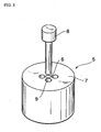
- Figure 2 shows an example of the method of making the preform.
- a plurality of through-holes 9 extending along the preform axis are formed around the core region 6 in the cladding region 7 of the preform 5 by drilling with a perforation tool 8 having an edge which has diamond grains on its surface.
- the through-holes 9 become the holes 4 of the optical fiber 1 by drawing as described later.
- the diameter of the through-holes 9 is 3 mm
- the length of the through-holes 9 (the height of preform 5) is 300 mm.
- the preform having the through-holes 9 can easily be manufactured at high yield.
- the preform does not have any cavity except for the holes formed by the perforation tool 8. Therefore, there is no need to remove impurities that may otherwise exist in such cavity. Consequently, it is possible to shorten the time needed for removal of the OH group in the second process, and the manufacturing cost can be reduced. Also, the contraction of the holes can be easily suppressed during the drawing process by adjusting the pressure in the holes of the preform.
- the core region 6 and the cladding region 7 of the above-mentioned preform 5 from the silica glass to which the dopants such as GeO 2 , F, TiO 2 , B 2 O 3 or P 2 O 5 are added.
- the refractive index can be changed in the preform 5 by altering the amount of dopants in the preform 5.
- the position of the through-holes 9 and the material refractive index profile of the preform 5 are selected such that light with a given wavelength is confined so as to be guided through the core 2 of the optical fiber 1 by total reflection or Bragg reflection.
- the through-holes that become the holes of an optical fiber can be arranged as shown in Figs. 3 through 5.
- a plurality of through-holes 9A are arranged in the preform 5A that consists of silica glass, and consequently, a cladding region 7A surrounds the core region 6A where the filling fraction of the holes is smaller than that in the cladding.
- An optical fiber that is produced from the preform 5A can let light travel in the axial direction of the fiber by confining the light in the core by total reflection. It is possible to achieve equivalently a large refractive index difference between the core and hence the cladding, and to attain a chromatic dispersion having a large absolute magnitude and a small mode field diameter.
- the former is preferable for application to dispersion compensation and the latter is preferable for the use of nonlinear optical effects.
- a plurality of through-holes 9B are arranged in a preform 5B which consists of silica glass, and consequently, a core region which includes a through-hole 6B is surrounded by a cladding region 7B which has a regular profile of refractive index in the direction of the diameter.
- the smoothing of the surfaces of the inner walls 5a of the through-holes 9 can be done by scraping the surfaces of the inner walls 5a directly with a file, or by filling diamond powder and a suitable solvent in the through-holes 9 and applying an ultrasonic wave thereto.
- the surface area of the surfaces of the inner walls 5a of the preform 5 is reduced, and accordingly this decreases the quantity of the OH group that exists on the inner wall surfaces 5a. Consequently, the time needed to remove the OH group in the second process is shortened and the manufacturing cost can be reduced.
- a wet etching by HF solution and a dry etching with SF 6 or the like are performed.
- the dry etching by SF 6 can be performed, for example, by introducing SF 6 into the through-holes 9 of the preform 5 which is heated to 1000 °C or more.
- the HF etching can remove contaminants that adhere to the surfaces of the inner walls 5a of the preform 5 at the time of drilling.
- the SF 6 etching smoothes the surfaces of the inner walls 5a, and removes a layer that includes the OH group on the surfaces of the inner walls 5a of the preform 5. This further decreases the quantity of the OH group which exists on the surfaces of the inner walls 5a, and thereby shortens the time needed to remove the OH group in the second process, which results in the further reduction of manufacturing cost.
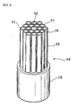
- a rod 10 made of silica glass and plurality of capillaries 11 made of silica glass are assembled to form a bundle 12.
- the rod 10, which forms the core of an optical fiber has approximately the same diameter as the diameter of a capillary 11. It is possible to provide different rods having a diameter less than half of the diameter of a capillary 11, as spacers to fill the spaces among capillaries 11 or among the glass rod 10 and capillaries 11.
- a preform 14 is formed by inserting the bundle 12 into a jacketing pipe 13 made of silica glass having an inner diameter slightly larger than the diameter of the bundle 12.
- the hollow region of a capillary 11 constitutes a through-hole 15 of preform 14.
- the diameter of the rod 10 and the capillary 11 is about 1 mm, and the ratio of the inner diameter to the outer diameter of the capillary 11 is 0.4 or 0.8, for example.
- the outer diameter is about 20 mm and the inner diameter is about 18 mm.
- a process is performed for removing the OH group that exists on the inner wall surfaces of through-holes in the preform.
- a setup for implementing the process of removing the OH group is shown in Fig. 7.
- the preform 5 which has through-holes 9 is set in the furnace of a drawing tower.
- Each end of the preform 5 is connected to an end of a glass pipe 21a or 21b, and the other end of each of the glass pipes 21a and 21b is fixed to a covering 22a or 22b. Consequently, in such structure, it is possible to prevent contaminants from entering into the through-holes 9 of the preform 5.
- the length of the glass pipes 21a and 21b is adjusted according to the coordination of the drawing tower.
- the glass pipe 21a is connected to a supply pipe 23a which supplies a dry gas into the through-holes 9 of the preform 5.
- the glass pipe 21b is connected to an exhaust pipe 23b for discharging a dry gas to the outside of the preform 5.
- dry gas means a substantially dry gas which includes a slight amount of moisture, as well as a completely dry gas.
- the glass pipes 21a and 21b are provided so that the effective portion of the preform 5, that is, the part which becomes an optical fiber after drawing, is connected to the supply pipe 23a, the exhaust pipe 23b, and a holding means (not illustrated).
- a dry gas is flowed, for example, at a flow rate of about 5 liters per minute through the through-holes 9 of the preform 5, from one end to the other end of the preform 5, while the preform 5 is heated by a heating means 24 in the furnace.
- the preform 5 is heated for 30 minutes or more at equal to or more than 800 °C, and more preferably for one hour or more at equal to or more than 1200 °C.
- the preform 5 may be moved up and down timely so that the whole preform effective portion is heated appropriately.
- Heating the preform 5 in this manner while flowing a dry gas through the through-holes 9 of the preform 5 promotes the reaction in which the OH group which exists on the surfaces of the inner walls 5a of the through-holes 9 of the preform 5 becomes H 2 O molecules.
- the OH group which exists on the inner wall surface of the preform diffuses to the spaces of the through-holes 9 as the H 2 O molecules.
- the diffused H 2 O molecules are discharged outside the preform through the exhaust pipe 23b by the flow of the dry gas without staying in the through-holes 9. Consequently, the OH concentration on the surfaces of the inner walls 5a decreases.
- a dry gas whose H 2 O concentration is sufficiently low More specifically, a dry gas whose dew point is -50 °C or less, more preferably -70 °C or less, is used. This results in further restraining the re-adsorption of OH to the inner wall surface of the preform, and consequently reducing the transmission loss of the optical fiber further more.
- a dry gas that includes an inert gas by equal to or more than 85 % in terms of molar fraction.
- a dry gas is chemically inactive, it does not react to silica glass easily, and consequently the chemical reaction between the gas and glass in the through-holes 9 is restrained. This results in the avoidance of the light absorption and the light scattering, and hence the deterioration of the transmission characteristics of the optical fiber can be prevented.
- an inert gas which includes one or more of N 2 , He, or Ar by equal to or more than 85 % in terms of molar fraction is preferable. These gases are especially inert and effective for restraining the chemical reaction with glass.
- a gas that includes an active gas having a dehydration effect can be used as a dry gas.
- the active gas having a dehydration effect a gas that includes at least one of HF, F 2 , Cl 2 , and CO is used. These gases have particularly excellent characteristics for dehydration effect and are effective for reducing the time needed for removing OH.
- the decrease of the OH concentration can be further accelerated when the concentration of active gas is high, for example, equal to or more than 30 %.
- the preform 5 After performing the process for removing the OH group as described above, the preform 5 is heated to about 1800 °C by the heating means 24 of the drawing tower. The heated portion of the preform 5 softens and narrows in a neck-like shape by the weight of the glass pipe 21b. The glass pipe 21b is detached from the preform 5 at this narrowed portion. Then, the preform 5 is drawn from the bottom end thereof into an optical fiber by a known method. Thus, an optical fiber 1 having a plurality of holes 4 as shown in Fig. 1 and having a 125 ⁇ m diameter is produced. When such drawing is done in a state in which the above-mentioned covering 22a is attached, contaminants such as moisture and the like are prevented from entering into the through-holes 9 of the preform 5, and hence the yield of drawing is improved.
- the filling fraction of holes of the optical fiber 1 is the value obtained by dividing the cross-sectional area of the holes of the fiber by the cross-sectional area of the fiber or the value obtained by dividing the cross-sectional area of the through-holes 9 of the preform 5 by the cross-sectional area of the preform 5.
- the filling fraction of holes at the time of such drawing also depends on the difference in pressure between the inside of the through-holes 9 of the preform 5 and the inner wall 5a. Therefore, a desired filling fraction of holes of the optical fiber 1 can be obtained by controlling the pressure in the through-holes 9.
- a pressure control unit 25 for adjusting the supply pressure of a dry gas and a pressure sensor 26 for measuring the pressure in the through-holes 9 of the preform 5 are provided in the supply pipe 23a.
- the pressure sensor 26 measures the pressure in the supply pipe 23a and the pressure in the through-holes 9 can be obtained based on the value thus measured.
- the pressure control unit 25 controls the supply pressure of a dry gas so that the pressure in the through-holes 9 becomes a desired value based on the value measured by the pressure sensor 26.
- the contraction of the through-holes 9 by the surface tension on the surfaces of the inner walls 5a of the preform 5 is restrained such that an optical fiber having a desired filling fraction of holes can be drawn.
- the filling fraction of holes of the optical fiber 1 can be controlled by adjusting the supply pressure of a dry gas. In this case, the characteristics of the fiber, such as the chromatic dispersion and the mode field diameter can be easily adjusted.
- the preform 30 of an optical fiber 1 has a plurality of holes 31 each of which extends axially and is closed at one end.
- the preform 30 is formed by perforating a glass rod 7 halfway, and in the method of assembling the capillaries 11 as shown in Fig. 6, the preform 30 is formed by using a jacketing pipe closed at one end.
- the process for removing the OH group, which exists on the surfaces of the inner walls 30a of the closed-end holes 31 in the preform 30, is performed in the setup shown in Fig. 8. As shown in Fig.
- one end of a glass pipe 32 is connected to the end of the preform 30 on the side having the openings, and the other end of the glass pipe 32 is provided with a covering 33.
- a pipe 34 which is connected to the covering 33, is connected in bifurcation to a supply pipe 35 for supplying a dry gas into the holes 31 having a closed end in the preform 30 and to an exhaust pipe 36 for discharging the dry gas in the holes 31 having a closed end.
- the exhaust pipe 36 is connected to a vacuum pump 37. Valves 38 and 39 are provided for the pipes 35 and 36, respectively.
- a dry gas is flowed to fill the holes 31 having a closed end in the preform 30.
- the preform 30 is heated by heating means 24 in the furnace at a temperature equal to or more than 800 °C for 30 minutes or more. Then, after the elapse of a predetermined time, in a state in which the valve 38 is closed and the valve 39 is opened, the gas in the holes 31 having a closed end is exhausted therefrom by a vacuum pump 37.
- the decrease of the OH concentration on the surfaces of the inner walls 30a can be facilitated by reducing the diffusion of the H 2 O molecules from the ineffective portion of the preform 30 to the effective portion of the preform 30.
- the method of reducing the diffusion of the H 2 O molecules from the ineffective portion of the preform to the effective portion of the preform there are several means, such as maintaining the temperature of the effective portion of the preform higher than that of the ineffective portion of the preform, or providing a hygroscopic medium for the ineffective portion of the preform, or making the capacity of the holes 31 having a closed end in the ineffective portion of the preform larger than that of the holes 31 having a closed end in the effective portion of the preform.
- the preform 30 is heated by the heating means 24 of the drawing tower, and is drawn into a fiber from the end of the preform 30 at the heated side thereof.
- the supply pressure of a dry gas is controlled by the pressure control unit 25 and the pressure sensor 26 provided in the supply pipe 35 so that the pressure in the holes 31 having a closed end of the preform 30 reaches a desired level. In this manner, the contraction of the holes 31 having a closed end due to the surface tension on the surfaces of the inner walls 30a of the preform 30 is restrained, and an optical fiber having a desired filling fraction of holes can be drawn.
- the preform 30 which has holes 31 having a closed end is formed. Subsequently, in a state in which the valve 38 is closed and the valve 39 is opened, the gas within the holes 31 having a closed end is evacuated by the vacuum pump 37, and the preform 30 is heated for 30 minutes or more at a temperature equal to or more than 800 °C by the heating means 24 in the furnace. As a result, the OH group which exists on the surfaces of the inner walls 30a of the holes 31 having a closed end in the preform 30 diffuses as H 2 O molecules into the spaces of the holes 31 having a closed end, and the H 2 O molecules are discharged outside the preform 30 due to the evacuation.
- a dry gas is flowed to fill the holes 31 having a closed end of the preform 30.
- the preform 30 is heated by the heating means 24 of the drawing tower and drawn into a fiber from the heated end of the preform 30.
- the OH group which exists on the surfaces of the inner walls 30a of the holes 31 having a closed end in the preform 30 diffuses as H 2 O molecules into the spaces in the holes having a closed end. Then, the H 2 O molecules are discharged outside the preform due to the evacuation. Consequently, it is possible to decrease the OH concentration on the wall surfaces of the preform, thereby reducing the transmission loss of the optical fiber which is caused by the OH group.
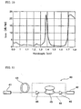
- Figure 9 shows an experimental example of the transmission loss of an optical fiber which was drawn as described below.
- the solid line P is the transmission loss in the case where a process was performed for removing the OH group which existed on the inner wall surfaces of the preform.
- N 2 having a dew point of -70 °C or less was used as a dry gas, and the preform was heated for 3 hours at the temperature of 1200 °C while flowing such N 2 into the holes of the preform.
- Figure 10 shows an experimental example of the transmission loss in the case where the wall surfaces of the preform were smoothed prior to the process of removing the OH group as described above.
- the transmission loss at 1380 nm which is the absorption peak wavelength for the OH group, is about 24 dB/km, and at the wavelength 1550 nm, the transmission loss is reduced to 0.68 dB/km.
- the loss due to the absorption of the OH group decreases, and the transmission loss in the 1100 - 1700 nm spectrum band is also reduced.
- the holes of the optical fiber are sealed at both ends of the optical fiber and are insulated from the outer air, so that the density of the water which exists inside the holes is thereby maintained at a level of 1 mg / liter or less for a sufficient period.
- the means of sealing the holes the methods such as melting the glass by heat, or sealing the ends of the holes with a highly transparent substance can be used, for example.
- the optical fiber 1 having the holes 4 whose transmission loss is small is suitable for use as a dispersion compensator.
- the dispersion quantity that can be compensated is increased, whereby allowing a transmission distance to be increased by elongating the transmission line whose dispersion is to be compensated.
- the compensating dispersion quantity can be further increased, thereby further increasing the transmission distance. Also, it is possible to increase the efficiency of spectrum use, that is, transmission capacity per frequency band, because the input light signal power of the dispersion compensator for achieving a given SN ratio can be reduced, and thereby suppressing the deterioration of transmission quality due to the nonlinear optical effects such as SPM, XPM, FWM, or the like.
- the compensating dispersion quantity can be further increased, and thereby the transmission distance can be additionally increased. Also, since the input light signal power of the dispersion compensator can be further reduced, the efficiency of spectrum use can be further increased. Also, in this case, since the transmission on the order of tens of km becomes possible, the fiber can be used suitably not only for a dispersion compensator, but also for an optical transmission line, and the transmission distance can be further increased. Also, light signal at the 1550 nm wavelength band can be amplified by stimulated Raman scattering by launching pump light near the 1400 nm wavelength thereon.
- Figure 12 shows another example of the optical communication system equipped with an optical transmission line which includes the optical fiber 1 shown in Fig. 1.
- an optical transmitter 51 and an optical receiver 52 are connected through an optical transmission line 53 and optical amplifiers 54.
- the optical fiber 1 used for the optical transmission line 53 is 30 km or longer in length and has a chromatic dispersion of 1 - 10 ps / nm/km in terms of absolute magnitude over the wide spectrum band of 50 nm or more. It is possible to increase the transmission distance further by connecting a plurality of optical transmission lines with an optical amplifier being provided therebetween. Since the chromatic dispersion of small absolute magnitude is obtained over the wide band as described above, it is possible to perform multiple wavelength transmission having a large transmission capacity per wavelength and a large number of wavelengths, and thereby a large transmission capacity can be obtained.
- Figure 13 shows another example of the optical communication system equipped with an optical transmission line which includes the optical fibers 1 shown in Fig. 1.
- an optical transmitter 61 and an optical receiver 62 are connected through the optical transmission line 63 and optical amplifiers 64.
- the optical transmission line 63 includes a transmission line 65 comprising an ordinary optical fiber which has no hole and a transmission line 66 comprising the optical fiber 1 having holes 4 as shown in Fig. 1.
- the ordinary optical fiber used for the transmission line 65 is 30 km or more in length and has the chromatic dispersion of +1 ps / nm/km.
- the optical fiber 1 used for transmission line 66 is 10 km or more in length and has the chromatic dispersion of -3 ps / nm/km.
- each optical fiber is selected such that the cumulative chromatic dispersion falls within a given range of value. It is possible to increase the transmission distance further by connecting a plurality of optical transmission lines with an optical amplifier provided therebetween.
- an optical fiber having absolute chromatic dispersion of a given value as described above the deterioration of the transmission quality due to nonlinear optical effects such as FWM or the like is restrained, and thereby the transmission capacity and the efficiency of spectrum use can be improved.
- the present invention is not limited to the above-described embodiments.
- the optical fibers in the above embodiments have holes solely in the cladding, but it is also possible to apply the present invention to an optical fiber having a hole in the core.
Landscapes
- Physics & Mathematics (AREA)
- Chemical & Material Sciences (AREA)
- Optics & Photonics (AREA)
- Engineering & Computer Science (AREA)
- General Physics & Mathematics (AREA)
- Life Sciences & Earth Sciences (AREA)
- General Life Sciences & Earth Sciences (AREA)
- Geochemistry & Mineralogy (AREA)
- Manufacturing & Machinery (AREA)
- Materials Engineering (AREA)
- Organic Chemistry (AREA)
- Crystallography & Structural Chemistry (AREA)
- Dispersion Chemistry (AREA)
- Optical Fibers, Optical Fiber Cores, And Optical Fiber Bundles (AREA)
- Manufacture, Treatment Of Glass Fibers (AREA)
Claims (16)
- Herstellungsverfahren für eine optische Faser mit einem oder mehreren Löchern, die sich entlang der Achse erstrecken, welches folgendes umfaßt:einen ersten Arbeitsvorgang zur Ausbildung einer Vorform mit mindestens einem Loch;einem zweiten Arbeitsvorgang zum Erwärmen der Vorform und Trocknen des Inneren der Löcher; undeinen dritten Arbeitsvorgang zum Ziehen der Vorform in eine optische Faser.
- Herstellungsverfahren für eine optische Faser gemäß Anspruch 1, bei dem mindestens ein Teil der Löcher Durchgangslöcher sind; und der zweite Arbeitsvorgang durchgeführt wird, während man ein trockenes Gas durch die Durchgangslöcher fließen läßt.
- Herstellungsverfahren für eine optische Faser gemäß Anspruch 1, bei dem mindestens ein Teil der Löcher ein verschlossenes Ende haben; und der zweite Arbeitsvorgang durchgeführt wird, während die Löcher mit einem verschlossenen Ende mit einem trockenen Gas gefüllt sind.
- Herstellungsverfahren für eine optische Faser gemäß Anspruch 3, bei dem der Arbeitsvorgang für das Einfüllen eines trockenen Gases in die Löcher mit einem verschlossenen Ende und der Arbeitsvorgang zur Entnahme des trockenen Gases aus den Löchern mit einem verschlossenen Ende im zweiten Arbeitsvorgang abwechselnd wiederholt werden.
- Herstellungsverfahren für eine optische Faser gemäß Anspruch 1, bei dem mindestens ein Teil der Löcher ein verschlossenes Ende haben; und der zweite Arbeitsvorgang durchgeführt wird, während das Innere der einen oder mehreren Löcher mit einem verschlossenen Ende zur Evakuierung einem verringerten Druck ausgesetzt wird.
- Herstellungsverfahren für eine optische Faser gemäß mindestens einem der Ansprüche 1 bis 5, bei dem beim zweiten Arbeitsvorgang die Vorform auf eine Temperatur gleich oder höher als 800°C erwärmt wird.
- Herstellungsverfahren für eine optische Faser gemäß mindestens einem der Ansprüche 2 bis 4 oder 6, bei dem der Taupunkt des trockenen Gases -50°C oder niedriger ist.
- Herstellungsverfahren für eine optische Faser gemäß Anspruch 7, bei dem das trockene Gas ein Inertgas mit einem molaren Anteil von gleich oder mehr als 85 % enthält.
- Herstellungsverfahren für eine optische Faser gemäß Anspruch 8, bei dem das Inertgas ausgewählt ist aus der Gruppe bestehend aus N2, He und Ar.
- Herstellungsverfahren für eine optische Faser gemäß Anspruch 7, bei dem das trockene Gas ein aktives Gas enthält, welches einen Dehydratationseffekt hat.
- Herstellungsverfahren für eine optische Faser gemäß Anspruch 10, bei dem das aktive Gas mit einem Dehydratationseffekt mindestens eines aus HF, F2, Cl2 und CO einschließt.
- Herstellungsverfahren für eine optische Faser gemäß mindestens einem der Ansprüche 1 bis 11, bei dem die inneren Wandflächen der Löcher der Vorform vor dem zweiten Arbeitsvorgang geglättet werden.
- Herstellungsverfahren für eine optische Faser gemäß mindestens einem der Ansprüche 1 bis 12, bei dem die inneren Wandflächen der Löcher der Vorform vor dem zweiten Arbeitsvorgang der Trockenätzung unterzogen werden.
- Herstellungsverfahren für eine optische Faser gemäß mindestens einem der Ansprüche 1 bis 13, bei dem während des dritten Arbeitsvorgangs der Druck in den Löchern eingestellt wird.
- Herstellungsverfahren für eine optische Faser gemäß mindestens einem der Ansprüche 1 bis 14, bei dem beim ersten Arbeitsvorgang die Vorform mit den Löchern gebildet wird aus einem säulenförmigen Glasstab unter Verwendung eines Perforationswerkzeugs.
- Herstellungsverfahren für eine optische Faser gemäß mindestens einem der Ansprüche 1 bis 14, bei dem beim ersten Arbeitsvorgang mehrere Kapillarröhrchen unter Bildung eines Bündels zusammengesetzt werden und das Bündel in ein Umhüllungsrohr eingesetzt wird, um die Vorform mit den Löchern zu bilden.
Applications Claiming Priority (2)
| Application Number | Priority Date | Filing Date | Title |
|---|---|---|---|
| JP2001045409 | 2001-02-21 | ||
| JP2001045409A JP4759816B2 (ja) | 2001-02-21 | 2001-02-21 | 光ファイバの製造方法 |
Publications (3)
| Publication Number | Publication Date |
|---|---|
| EP1234806A2 EP1234806A2 (de) | 2002-08-28 |
| EP1234806A3 EP1234806A3 (de) | 2004-06-30 |
| EP1234806B1 true EP1234806B1 (de) | 2007-02-07 |
Family
ID=18907207
Family Applications (1)
| Application Number | Title | Priority Date | Filing Date |
|---|---|---|---|
| EP02003258A Expired - Lifetime EP1234806B1 (de) | 2001-02-21 | 2002-02-21 | Verfahren zur Herstellung einer optischen Faser |
Country Status (5)
| Country | Link |
|---|---|
| US (1) | US20020118938A1 (de) |
| EP (1) | EP1234806B1 (de) |
| JP (1) | JP4759816B2 (de) |
| DE (1) | DE60217982T2 (de) |
| DK (1) | DK1234806T3 (de) |
Families Citing this family (42)
| Publication number | Priority date | Publication date | Assignee | Title |
|---|---|---|---|---|
| FR2822242B1 (fr) * | 2001-03-16 | 2003-08-15 | Cit Alcatel | Fibre optique photonique a forte surface effective |
| EP1414763B1 (de) * | 2001-07-06 | 2012-11-28 | Corning Incorporated | Verfahren zur herstellung von fasern mit photonischer bandlücke |
| US6496634B1 (en) * | 2001-07-17 | 2002-12-17 | Marc David Levenson | Holey fibers filled with raman active fluid |
| US6661957B1 (en) * | 2001-07-17 | 2003-12-09 | Marc David Levenson | Diffusion barriers for holey fibers |
| GB0201492D0 (en) * | 2002-01-23 | 2002-03-13 | Blazephotonics Ltd | A method and apparatus relating to optical fibres |
| JP4466813B2 (ja) * | 2002-03-14 | 2010-05-26 | 日本電気硝子株式会社 | ガラスプリフォームおよびその製造方法 |
| JP3978071B2 (ja) * | 2002-04-17 | 2007-09-19 | 正隆 中沢 | ホーリーファイバ製造方法 |
| JP3962277B2 (ja) * | 2002-04-17 | 2007-08-22 | 正隆 中沢 | フォトニッククリスタル光ファイバ母材の製造方法 |
| FR2843746B1 (fr) * | 2002-08-22 | 2004-11-19 | Cit Alcatel | Procede de fabrication d'une fibre optique a microstructure |
| JP3870885B2 (ja) * | 2002-09-24 | 2007-01-24 | 日立電線株式会社 | 光ファイバコード及びその曲げ配線方法 |
| JP2004191947A (ja) * | 2002-11-25 | 2004-07-08 | Shin Etsu Chem Co Ltd | 空孔ファイバの線引き方法 |
| JP2004191400A (ja) * | 2002-12-06 | 2004-07-08 | Hitachi Cable Ltd | 単一モード紫外線伝送ファイバ及びそれを用いた紫外線照射装置 |
| JP2004191399A (ja) * | 2002-12-06 | 2004-07-08 | Hitachi Cable Ltd | 低損失紫外線伝送ファイバ及びそれを用いた紫外線照射装置 |
| JP4220261B2 (ja) * | 2003-02-12 | 2009-02-04 | 三菱電線工業株式会社 | フォトニッククリスタルファイバの製造方法 |
| JP3854627B2 (ja) * | 2003-04-17 | 2006-12-06 | 日本電信電話株式会社 | 空孔付き単一モード光ファイバ |
| AU2003246376A1 (en) * | 2003-06-30 | 2005-01-21 | Pirelli And C. S.P.A. | Method and apparatus for drilling preforms for holey optical fibers |
| JP2005055626A (ja) * | 2003-08-04 | 2005-03-03 | Nippon Telegr & Teleph Corp <Ntt> | 光ファイバ及びその製造方法 |
| JP4046054B2 (ja) * | 2003-09-05 | 2008-02-13 | 日立電線株式会社 | フォトニッククリスタルファイバ及びその製造方法 |
| JP2005247620A (ja) * | 2004-03-03 | 2005-09-15 | Masataka Nakazawa | フォトニッククリスタルファイバの製造方法 |
| JP4172440B2 (ja) * | 2004-09-15 | 2008-10-29 | 住友電気工業株式会社 | 光ファイバの製造方法 |
| JP2006177780A (ja) * | 2004-12-22 | 2006-07-06 | Hitachi Cable Ltd | 光ファイバ温度センサ、温度センサシート及び温度測定方法 |
| WO2006098471A1 (ja) * | 2005-03-18 | 2006-09-21 | The Furukawa Electric Co., Ltd. | 光ファイバおよび導波路 |
| US20070201793A1 (en) * | 2006-02-17 | 2007-08-30 | Charles Askins | Multi-core optical fiber and method of making and using same |
| US7793521B2 (en) * | 2006-03-01 | 2010-09-14 | Corning Incorporated | Method enabling dual pressure control within fiber preform during fiber fabrication |
| DE102006019333A1 (de) * | 2006-04-24 | 2007-10-25 | Heraeus Tenevo Gmbh | Verfahren und Vorform zur Herstellung einer mikrostrukturierten optischen Faser sowie nach dem Verfahren erhaltene Faser |
| EP2056135B1 (de) * | 2006-11-21 | 2015-06-10 | The Furukawa Electric Co., Ltd. | Glasfaser und lichtleiter |
| US7346250B1 (en) * | 2007-03-30 | 2008-03-18 | Corning Incorporated | Preferential etching method of forming microstructure for an optical waveguide |
| CA2755374C (en) * | 2009-03-23 | 2015-09-15 | Sekisui Chemical Co., Ltd. | Extrusion material supply device and optical transmission body manufacturing method using the same |
| JP5457089B2 (ja) * | 2009-06-29 | 2014-04-02 | 株式会社フジクラ | フォトニックバンドギャップファイバ用母材の製造方法、及び、フォトニックバンドギャップファイバの製造方法 |
| JP5603286B2 (ja) * | 2011-04-25 | 2014-10-08 | 湖北工業株式会社 | ファイバ |
| JP5551657B2 (ja) | 2011-07-26 | 2014-07-16 | 株式会社フジクラ | 検査装置、検査方法、および光ファイバの製造方法 |
| JP5705758B2 (ja) * | 2012-01-25 | 2015-04-22 | コーニング インコーポレイテッド | フォトニックバンドギャップファイバの製造方法 |
| EP3047319B8 (de) * | 2013-09-20 | 2021-06-30 | University Of Southampton | Fotonische bandlückenfasern mit hohlem kern und verfahren zur herstellung davon |
| FR3036110A1 (fr) * | 2015-05-15 | 2016-11-18 | Centre Nat De La Rech Scient - Cnrs | Fibre optique ruban en verre photosensible |
| CN108473356B (zh) | 2015-11-10 | 2022-05-17 | Nkt光子学有限公司 | 用于预制件的元件、纤维生产方法和由预制件拉制的光纤 |
| SG11201804738SA (en) | 2015-12-23 | 2018-07-30 | Nkt Photonics As | Hollow core optical fiber and a laser system |
| KR102677212B1 (ko) | 2015-12-23 | 2024-06-24 | 엔케이티 포토닉스 에이/에스 | 광결정 섬유 조립체 |
| EP3448818B1 (de) * | 2016-04-27 | 2024-09-25 | NKT Photonics A/S | Verfahren zur faserherstellung |
| CN109581580A (zh) * | 2018-12-12 | 2019-04-05 | 桂林电子科技大学 | 一种基于空芯光子晶体光纤的光纤光栅器件 |
| US12195380B2 (en) * | 2021-03-31 | 2025-01-14 | Sterlite Technologies Limited | Preform assembly for drawing multicore or holey optical fibre and method of manufacturing thereof |
| JPWO2024171282A1 (de) * | 2023-02-14 | 2024-08-22 | ||
| CN119846768B (zh) * | 2025-01-13 | 2025-08-12 | 北京工业大学 | 一种低损耗光传输丝芯光纤及制备方法 |
Family Cites Families (28)
| Publication number | Priority date | Publication date | Assignee | Title |
|---|---|---|---|---|
| US3622291A (en) * | 1969-06-03 | 1971-11-23 | Weston Instruments Inc | Tube uniting with end fractures |
| US3711262A (en) * | 1970-05-11 | 1973-01-16 | Corning Glass Works | Method of producing optical waveguide fibers |
| US3823995A (en) * | 1972-03-30 | 1974-07-16 | Corning Glass Works | Method of forming light focusing fiber waveguide |
| US4157906A (en) * | 1978-02-21 | 1979-06-12 | Corning Glass Works | Method of drawing glass optical waveguides |
| US4251251A (en) * | 1979-05-31 | 1981-02-17 | Corning Glass Works | Method of making optical devices |
| US4693551A (en) * | 1983-10-05 | 1987-09-15 | U.S. Holding Company, Inc. | Dielectric strength elements for loose tube optical fiber cable |
| US4561871A (en) * | 1983-12-27 | 1985-12-31 | Corning Glass Works | Method of making polarization preserving optical fiber |
| JPS61227938A (ja) * | 1985-04-03 | 1986-10-11 | Sumitomo Electric Ind Ltd | 光フアイバ用母材の製造方法 |
| JP2584619B2 (ja) * | 1986-07-03 | 1997-02-26 | 株式会社フジクラ | 非軸対称光フアイバ母材の製造方法 |
| JPH064490B2 (ja) * | 1987-12-09 | 1994-01-19 | 住友電気工業株式会社 | 定偏波光フアイバの製造方法 |
| FR2655326B1 (fr) * | 1989-12-01 | 1992-02-21 | Thomson Csf | Procede de realisation d'une fibre optique creuse et dispositif de realisation d'une fibre optique creuse. |
| AU639125B2 (en) * | 1990-08-09 | 1993-07-15 | Sumitomo Electric Industries, Ltd. | Method for producing preform for polarization retaining optical fiber |
| US5152818A (en) * | 1990-11-09 | 1992-10-06 | Corning Incorporated | Method of making polarization retaining fiber |
| FR2683053B1 (fr) * | 1991-10-29 | 1994-10-07 | Thomson Csf | Fibre optique et procede de fabrication. |
| EP0598349B1 (de) * | 1992-11-19 | 1998-07-29 | Shin-Etsu Quartz Products Co., Ltd. | Verfahren zur Herstellung eines grossen Quarzglasrohres, sowie einer Vorform und einer optischen Faser |
| US5802236A (en) * | 1997-02-14 | 1998-09-01 | Lucent Technologies Inc. | Article comprising a micro-structured optical fiber, and method of making such fiber |
| EP0810453B1 (de) * | 1996-05-31 | 2001-10-10 | Lucent Technologies Inc. | Artikel mit einer mikrostrukturierten optischen Faser und Verfahren zur Herstellung einer solchen Faser |
| ID28248A (id) * | 1998-09-15 | 2001-05-10 | Corning Inc | Pemandu-gelombang yang memiliki struktur yang bervariasi dalam arah aksial |
| WO2000049436A1 (en) * | 1999-02-19 | 2000-08-24 | Blazephotonics Limited | Improvements in or relating to photonic crystal fibres |
| US6097870A (en) * | 1999-05-17 | 2000-08-01 | Lucent Technologies Inc. | Article utilizing optical waveguides with anomalous dispersion at vis-nir wavelenghts |
| JP2001020165A (ja) * | 1999-07-08 | 2001-01-23 | Oji Paper Co Ltd | 石膏ボード補強材用不織布及び石膏ボード |
| JP3815170B2 (ja) * | 2000-02-14 | 2006-08-30 | 住友電気工業株式会社 | 微細構造光ファイバ用母材及び微細構造光ファイバの製造方法 |
| US6526209B1 (en) * | 2000-04-17 | 2003-02-25 | Sumitomo Electric Industries, Ltd. | Optical fiber having improved optics and structure |
| JP2002145634A (ja) * | 2000-08-30 | 2002-05-22 | Sumitomo Electric Ind Ltd | 光ファイバの製造方法、及び、光ファイバ |
| JP3556908B2 (ja) * | 2001-01-15 | 2004-08-25 | 三菱電線工業株式会社 | フォトニッククリスタルファイバの製造方法 |
| JP3576947B2 (ja) * | 2000-09-21 | 2004-10-13 | 三菱電線工業株式会社 | フォトニッククリスタルファイバの製造方法 |
| JP3513101B2 (ja) * | 2000-10-30 | 2004-03-31 | 三菱電線工業株式会社 | フォトニッククリスタルファイバの製造方法 |
| US7314751B2 (en) * | 2000-10-30 | 2008-01-01 | The Charles Stark Draper Laboratory, Inc. | Fluorescence detection system including a photonic band gap structure |
-
2001
- 2001-02-21 JP JP2001045409A patent/JP4759816B2/ja not_active Expired - Fee Related
-
2002
- 2002-02-19 US US10/076,603 patent/US20020118938A1/en not_active Abandoned
- 2002-02-21 DE DE60217982T patent/DE60217982T2/de not_active Expired - Lifetime
- 2002-02-21 DK DK02003258T patent/DK1234806T3/da active
- 2002-02-21 EP EP02003258A patent/EP1234806B1/de not_active Expired - Lifetime
Also Published As
| Publication number | Publication date |
|---|---|
| DE60217982D1 (de) | 2007-03-22 |
| EP1234806A2 (de) | 2002-08-28 |
| EP1234806A3 (de) | 2004-06-30 |
| JP4759816B2 (ja) | 2011-08-31 |
| DE60217982T2 (de) | 2007-10-25 |
| DK1234806T3 (da) | 2007-05-21 |
| US20020118938A1 (en) | 2002-08-29 |
| JP2002249335A (ja) | 2002-09-06 |
Similar Documents
| Publication | Publication Date | Title |
|---|---|---|
| EP1234806A2 (de) | Optische Faser mit länglichen Löchern und Verfahren zu ihrer Herstellung | |
| US6944382B2 (en) | Low water peak optical waveguide fiber | |
| DK1975655T3 (en) | Optical fibers, ultra high numerical aperture | |
| US7930904B2 (en) | Method of making an optical fiber having voids | |
| US4453961A (en) | Method of making glass optical fiber | |
| US8295668B2 (en) | Low loss optical fiber designs and methods for their manufacture | |
| US20050238307A1 (en) | Nonlinear optical fibre method of its production and use thereof | |
| EP0810453A1 (de) | Artikel mit einer mikrostrukturierten optischen Faser und Verfahren zur Herstellung einer solchen Faser | |
| US6943935B2 (en) | Dispersion-managed cable for raman-assisted transmission | |
| US9904007B2 (en) | Photonic band gap fibers using a jacket with a depressed softening temperature | |
| KR100963812B1 (ko) | 미세구조 광섬유 및 이의 제조방법 | |
| WO2004095099A1 (en) | Photonic band gap optical fiber | |
| US4784465A (en) | Method of making glass optical fiber | |
| JP3798984B2 (ja) | フォトニッククリスタル光ファイバの製造方法 | |
| JP4015959B2 (ja) | 高耐応力光ファイバ | |
| US6895155B2 (en) | Method of fabricating an optical fiber with microstructures | |
| JP4434172B2 (ja) | 分散補償光ファイバ | |
| JP2004226540A (ja) | 高耐応力光ファイバ | |
| JP2007297254A (ja) | 光ファイバ | |
| JP2004226539A (ja) | 光ファイバ及びその製造方法 | |
| JP2003313045A (ja) | ホーリーファイバ製造方法 |
Legal Events
| Date | Code | Title | Description |
|---|---|---|---|
| PUAI | Public reference made under article 153(3) epc to a published international application that has entered the european phase |
Free format text: ORIGINAL CODE: 0009012 |
|
| AK | Designated contracting states |
Kind code of ref document: A2 Designated state(s): AT BE CH CY DE DK ES FI FR GB GR IE IT LI LU MC NL PT SE TR |
|
| AX | Request for extension of the european patent |
Free format text: AL;LT;LV;MK;RO;SI |
|
| PUAL | Search report despatched |
Free format text: ORIGINAL CODE: 0009013 |
|
| AK | Designated contracting states |
Kind code of ref document: A3 Designated state(s): AT BE CH CY DE DK ES FI FR GB GR IE IT LI LU MC NL PT SE TR |
|
| AX | Request for extension of the european patent |
Extension state: AL LT LV MK RO SI |
|
| RIC1 | Information provided on ipc code assigned before grant |
Ipc: 7C 03B 37/012 A |
|
| 17P | Request for examination filed |
Effective date: 20040701 |
|
| 17Q | First examination report despatched |
Effective date: 20040802 |
|
| AKX | Designation fees paid |
Designated state(s): DE DK FR GB IT |
|
| GRAP | Despatch of communication of intention to grant a patent |
Free format text: ORIGINAL CODE: EPIDOSNIGR1 |
|
| RTI1 | Title (correction) |
Free format text: MANUFACTURING METHOD THEREOF OF AN OPTICAL FIBER |
|
| GRAS | Grant fee paid |
Free format text: ORIGINAL CODE: EPIDOSNIGR3 |
|
| GRAA | (expected) grant |
Free format text: ORIGINAL CODE: 0009210 |
|
| AK | Designated contracting states |
Kind code of ref document: B1 Designated state(s): DE DK FR GB IT |
|
| REG | Reference to a national code |
Ref country code: GB Ref legal event code: FG4D |
|
| RIN1 | Information on inventor provided before grant (corrected) |
Inventor name: HASEGAWA, TAKEMI,YOKOHAMA WORKS Inventor name: ONISHI, MASASHI,YOKOHAMA WORKS |
|
| RTI1 | Title (correction) |
Free format text: MANUFACTURING METHOD THEREOF OF AN OPTICAL FIBRE |
|
| REF | Corresponds to: |
Ref document number: 60217982 Country of ref document: DE Date of ref document: 20070322 Kind code of ref document: P |
|
| REG | Reference to a national code |
Ref country code: DK Ref legal event code: T3 |
|
| ET | Fr: translation filed | ||
| PLBE | No opposition filed within time limit |
Free format text: ORIGINAL CODE: 0009261 |
|
| STAA | Information on the status of an ep patent application or granted ep patent |
Free format text: STATUS: NO OPPOSITION FILED WITHIN TIME LIMIT |
|
| 26N | No opposition filed |
Effective date: 20071108 |
|
| REG | Reference to a national code |
Ref country code: GB Ref legal event code: 746 Effective date: 20121119 |
|
| REG | Reference to a national code |
Ref country code: DE Ref legal event code: R084 Ref document number: 60217982 Country of ref document: DE Effective date: 20121115 |
|
| PGFP | Annual fee paid to national office [announced via postgrant information from national office to epo] |
Ref country code: IT Payment date: 20140109 Year of fee payment: 13 |
|
| PGFP | Annual fee paid to national office [announced via postgrant information from national office to epo] |
Ref country code: GB Payment date: 20140219 Year of fee payment: 13 |
|
| GBPC | Gb: european patent ceased through non-payment of renewal fee |
Effective date: 20150221 |
|
| PG25 | Lapsed in a contracting state [announced via postgrant information from national office to epo] |
Ref country code: IT Free format text: LAPSE BECAUSE OF NON-PAYMENT OF DUE FEES Effective date: 20150221 |
|
| REG | Reference to a national code |
Ref country code: FR Ref legal event code: PLFP Year of fee payment: 15 |
|
| PG25 | Lapsed in a contracting state [announced via postgrant information from national office to epo] |
Ref country code: GB Free format text: LAPSE BECAUSE OF NON-PAYMENT OF DUE FEES Effective date: 20150221 |
|
| REG | Reference to a national code |
Ref country code: FR Ref legal event code: PLFP Year of fee payment: 16 |
|
| PGFP | Annual fee paid to national office [announced via postgrant information from national office to epo] |
Ref country code: DE Payment date: 20170214 Year of fee payment: 16 Ref country code: FR Payment date: 20170112 Year of fee payment: 16 |
|
| PGFP | Annual fee paid to national office [announced via postgrant information from national office to epo] |
Ref country code: DK Payment date: 20170210 Year of fee payment: 16 |
|
| REG | Reference to a national code |
Ref country code: DE Ref legal event code: R119 Ref document number: 60217982 Country of ref document: DE |
|
| REG | Reference to a national code |
Ref country code: DK Ref legal event code: EBP Effective date: 20180228 |
|
| REG | Reference to a national code |
Ref country code: FR Ref legal event code: ST Effective date: 20181031 |
|
| PG25 | Lapsed in a contracting state [announced via postgrant information from national office to epo] |
Ref country code: DK Free format text: LAPSE BECAUSE OF NON-PAYMENT OF DUE FEES Effective date: 20180228 Ref country code: DE Free format text: LAPSE BECAUSE OF NON-PAYMENT OF DUE FEES Effective date: 20180901 |
|
| PG25 | Lapsed in a contracting state [announced via postgrant information from national office to epo] |
Ref country code: FR Free format text: LAPSE BECAUSE OF NON-PAYMENT OF DUE FEES Effective date: 20180228 |