EP1234896A1 - Elektrolytisches phosphatchemisches Behandlungsverfahren - Google Patents
Elektrolytisches phosphatchemisches Behandlungsverfahren Download PDFInfo
- Publication number
- EP1234896A1 EP1234896A1 EP02003269A EP02003269A EP1234896A1 EP 1234896 A1 EP1234896 A1 EP 1234896A1 EP 02003269 A EP02003269 A EP 02003269A EP 02003269 A EP02003269 A EP 02003269A EP 1234896 A1 EP1234896 A1 EP 1234896A1
- Authority
- EP
- European Patent Office
- Prior art keywords
- treatment
- electrolytic
- phosphate chemical
- treatment bath
- chemical treatment
- Prior art date
- Legal status (The legal status is an assumption and is not a legal conclusion. Google has not performed a legal analysis and makes no representation as to the accuracy of the status listed.)
- Withdrawn
Links
- 238000011282 treatment Methods 0.000 title claims abstract description 442
- 239000000126 substance Substances 0.000 title claims abstract description 154
- 229910019142 PO4 Inorganic materials 0.000 title claims abstract description 148
- NBIIXXVUZAFLBC-UHFFFAOYSA-K phosphate Chemical compound [O-]P([O-])([O-])=O NBIIXXVUZAFLBC-UHFFFAOYSA-K 0.000 title claims abstract description 139
- 239000010452 phosphate Substances 0.000 title claims abstract description 127
- 238000000034 method Methods 0.000 title claims abstract description 37
- NBIIXXVUZAFLBC-UHFFFAOYSA-N Phosphoric acid Chemical compound OP(O)(O)=O NBIIXXVUZAFLBC-UHFFFAOYSA-N 0.000 claims abstract description 86
- 150000002500 ions Chemical class 0.000 claims abstract description 35
- 229910052751 metal Inorganic materials 0.000 claims abstract description 32
- 239000002184 metal Substances 0.000 claims abstract description 32
- 229910002651 NO3 Inorganic materials 0.000 claims abstract description 31
- 229910000147 aluminium phosphate Inorganic materials 0.000 claims abstract description 31
- XLYOFNOQVPJJNP-UHFFFAOYSA-N water Substances O XLYOFNOQVPJJNP-UHFFFAOYSA-N 0.000 claims abstract description 26
- 238000000354 decomposition reaction Methods 0.000 claims abstract description 25
- 229910021645 metal ion Inorganic materials 0.000 claims abstract description 24
- UFHFLCQGNIYNRP-UHFFFAOYSA-N Hydrogen Chemical compound [H][H] UFHFLCQGNIYNRP-UHFFFAOYSA-N 0.000 claims abstract description 22
- 239000001257 hydrogen Substances 0.000 claims abstract description 18
- 229910052739 hydrogen Inorganic materials 0.000 claims abstract description 18
- 239000002904 solvent Substances 0.000 claims abstract description 17
- -1 phosphate compound Chemical class 0.000 claims abstract description 16
- 238000001556 precipitation Methods 0.000 claims abstract description 15
- 239000007769 metal material Substances 0.000 claims abstract description 13
- 230000002829 reductive effect Effects 0.000 claims abstract description 11
- 239000002244 precipitate Substances 0.000 claims abstract description 9
- 230000033116 oxidation-reduction process Effects 0.000 claims abstract description 7
- 238000010349 cathodic reaction Methods 0.000 claims abstract description 5
- 238000005868 electrolysis reaction Methods 0.000 claims description 68
- 239000007789 gas Substances 0.000 claims description 53
- MWUXSHHQAYIFBG-UHFFFAOYSA-N nitrogen oxide Inorganic materials O=[N] MWUXSHHQAYIFBG-UHFFFAOYSA-N 0.000 claims description 33
- 239000007788 liquid Substances 0.000 claims description 31
- 230000007246 mechanism Effects 0.000 claims description 23
- 239000007787 solid Substances 0.000 claims description 14
- 239000000463 material Substances 0.000 claims description 12
- 239000000203 mixture Substances 0.000 claims description 12
- 230000008859 change Effects 0.000 claims description 10
- 229910000831 Steel Inorganic materials 0.000 claims description 8
- 239000010959 steel Substances 0.000 claims description 8
- 229910052742 iron Inorganic materials 0.000 claims description 4
- 229910001424 calcium ion Inorganic materials 0.000 claims description 3
- 239000007772 electrode material Substances 0.000 claims description 3
- 229910052748 manganese Inorganic materials 0.000 claims description 3
- 229910052725 zinc Inorganic materials 0.000 claims description 3
- 238000006243 chemical reaction Methods 0.000 abstract description 121
- 239000010802 sludge Substances 0.000 abstract description 42
- 230000015572 biosynthetic process Effects 0.000 abstract description 39
- 239000000243 solution Substances 0.000 description 80
- XEEYBQQBJWHFJM-UHFFFAOYSA-N Iron Chemical compound [Fe] XEEYBQQBJWHFJM-UHFFFAOYSA-N 0.000 description 70
- 239000011248 coating agent Substances 0.000 description 47
- 238000000576 coating method Methods 0.000 description 47
- 239000012071 phase Substances 0.000 description 45
- 238000005755 formation reaction Methods 0.000 description 40
- 235000011007 phosphoric acid Nutrition 0.000 description 29
- 238000003487 electrochemical reaction Methods 0.000 description 26
- 230000000630 rising effect Effects 0.000 description 24
- NHNBFGGVMKEFGY-UHFFFAOYSA-N Nitrate Chemical compound [O-][N+]([O-])=O NHNBFGGVMKEFGY-UHFFFAOYSA-N 0.000 description 21
- 230000000052 comparative effect Effects 0.000 description 21
- 230000007423 decrease Effects 0.000 description 21
- 238000004070 electrodeposition Methods 0.000 description 21
- 238000004381 surface treatment Methods 0.000 description 19
- 238000001914 filtration Methods 0.000 description 17
- 238000005260 corrosion Methods 0.000 description 16
- 230000007797 corrosion Effects 0.000 description 16
- PXHVJJICTQNCMI-UHFFFAOYSA-N Nickel Chemical compound [Ni] PXHVJJICTQNCMI-UHFFFAOYSA-N 0.000 description 15
- 238000010494 dissociation reaction Methods 0.000 description 15
- 230000005593 dissociations Effects 0.000 description 15
- 238000009713 electroplating Methods 0.000 description 11
- 238000011156 evaluation Methods 0.000 description 11
- 230000002093 peripheral effect Effects 0.000 description 11
- 238000010530 solution phase reaction Methods 0.000 description 11
- 229910021607 Silver chloride Inorganic materials 0.000 description 9
- 238000006722 reduction reaction Methods 0.000 description 9
- HKZLPVFGJNLROG-UHFFFAOYSA-M silver monochloride Chemical compound [Cl-].[Ag+] HKZLPVFGJNLROG-UHFFFAOYSA-M 0.000 description 9
- 239000011701 zinc Substances 0.000 description 9
- 238000005516 engineering process Methods 0.000 description 8
- 238000002474 experimental method Methods 0.000 description 8
- 238000004090 dissolution Methods 0.000 description 7
- PTFCDOFLOPIGGS-UHFFFAOYSA-N Zinc dication Chemical compound [Zn+2] PTFCDOFLOPIGGS-UHFFFAOYSA-N 0.000 description 6
- 230000009471 action Effects 0.000 description 6
- 238000009835 boiling Methods 0.000 description 6
- 239000004744 fabric Substances 0.000 description 6
- 238000012360 testing method Methods 0.000 description 6
- 230000007704 transition Effects 0.000 description 6
- 230000004308 accommodation Effects 0.000 description 5
- 238000005238 degreasing Methods 0.000 description 5
- 238000004519 manufacturing process Methods 0.000 description 5
- 230000008569 process Effects 0.000 description 5
- MYMOFIZGZYHOMD-UHFFFAOYSA-N Dioxygen Chemical compound O=O MYMOFIZGZYHOMD-UHFFFAOYSA-N 0.000 description 4
- 238000004458 analytical method Methods 0.000 description 4
- 229910001882 dioxygen Inorganic materials 0.000 description 4
- 230000000694 effects Effects 0.000 description 4
- XLYOFNOQVPJJNP-ZSJDYOACSA-N heavy water Substances [2H]O[2H] XLYOFNOQVPJJNP-ZSJDYOACSA-N 0.000 description 4
- VEQPNABPJHWNSG-UHFFFAOYSA-N Nickel(2+) Chemical compound [Ni+2] VEQPNABPJHWNSG-UHFFFAOYSA-N 0.000 description 3
- QVGXLLKOCUKJST-UHFFFAOYSA-N atomic oxygen Chemical compound [O] QVGXLLKOCUKJST-UHFFFAOYSA-N 0.000 description 3
- 239000010949 copper Substances 0.000 description 3
- 239000013527 degreasing agent Substances 0.000 description 3
- 239000011572 manganese Substances 0.000 description 3
- 239000001301 oxygen Substances 0.000 description 3
- 229910052760 oxygen Inorganic materials 0.000 description 3
- 229940085991 phosphate ion Drugs 0.000 description 3
- 230000002265 prevention Effects 0.000 description 3
- 229910001415 sodium ion Inorganic materials 0.000 description 3
- FAPWRFPIFSIZLT-UHFFFAOYSA-M Sodium chloride Chemical compound [Na+].[Cl-] FAPWRFPIFSIZLT-UHFFFAOYSA-M 0.000 description 2
- 239000002253 acid Substances 0.000 description 2
- 125000002091 cationic group Chemical group 0.000 description 2
- 239000000470 constituent Substances 0.000 description 2
- 238000011109 contamination Methods 0.000 description 2
- 230000001627 detrimental effect Effects 0.000 description 2
- 238000009826 distribution Methods 0.000 description 2
- 239000000284 extract Substances 0.000 description 2
- GPRLSGONYQIRFK-UHFFFAOYSA-N hydron Chemical compound [H+] GPRLSGONYQIRFK-UHFFFAOYSA-N 0.000 description 2
- 238000007654 immersion Methods 0.000 description 2
- 239000012535 impurity Substances 0.000 description 2
- 230000000670 limiting effect Effects 0.000 description 2
- 239000010687 lubricating oil Substances 0.000 description 2
- 229910001453 nickel ion Inorganic materials 0.000 description 2
- 238000007254 oxidation reaction Methods 0.000 description 2
- 230000009257 reactivity Effects 0.000 description 2
- 230000009467 reduction Effects 0.000 description 2
- 239000000758 substrate Substances 0.000 description 2
- BHPQYMZQTOCNFJ-UHFFFAOYSA-N Calcium cation Chemical compound [Ca+2] BHPQYMZQTOCNFJ-UHFFFAOYSA-N 0.000 description 1
- RYGMFSIKBFXOCR-UHFFFAOYSA-N Copper Chemical compound [Cu] RYGMFSIKBFXOCR-UHFFFAOYSA-N 0.000 description 1
- XFXPMWWXUTWYJX-UHFFFAOYSA-N Cyanide Chemical compound N#[C-] XFXPMWWXUTWYJX-UHFFFAOYSA-N 0.000 description 1
- PWHULOQIROXLJO-UHFFFAOYSA-N Manganese Chemical compound [Mn] PWHULOQIROXLJO-UHFFFAOYSA-N 0.000 description 1
- FKNQFGJONOIPTF-UHFFFAOYSA-N Sodium cation Chemical compound [Na+] FKNQFGJONOIPTF-UHFFFAOYSA-N 0.000 description 1
- RTAQQCXQSZGOHL-UHFFFAOYSA-N Titanium Chemical compound [Ti] RTAQQCXQSZGOHL-UHFFFAOYSA-N 0.000 description 1
- 101100020289 Xenopus laevis koza gene Proteins 0.000 description 1
- HCHKCACWOHOZIP-UHFFFAOYSA-N Zinc Chemical compound [Zn] HCHKCACWOHOZIP-UHFFFAOYSA-N 0.000 description 1
- 150000007513 acids Chemical class 0.000 description 1
- 239000002390 adhesive tape Substances 0.000 description 1
- 238000004220 aggregation Methods 0.000 description 1
- 230000002776 aggregation Effects 0.000 description 1
- 239000010405 anode material Substances 0.000 description 1
- 238000013459 approach Methods 0.000 description 1
- 239000007864 aqueous solution Substances 0.000 description 1
- 229910052802 copper Inorganic materials 0.000 description 1
- 239000013078 crystal Substances 0.000 description 1
- 238000000151 deposition Methods 0.000 description 1
- 230000008021 deposition Effects 0.000 description 1
- 230000008030 elimination Effects 0.000 description 1
- 238000003379 elimination reaction Methods 0.000 description 1
- 230000002349 favourable effect Effects 0.000 description 1
- 230000006872 improvement Effects 0.000 description 1
- 230000002401 inhibitory effect Effects 0.000 description 1
- 238000011221 initial treatment Methods 0.000 description 1
- MVFCKEFYUDZOCX-UHFFFAOYSA-N iron(2+);dinitrate Chemical compound [Fe+2].[O-][N+]([O-])=O.[O-][N+]([O-])=O MVFCKEFYUDZOCX-UHFFFAOYSA-N 0.000 description 1
- VCJMYUPGQJHHFU-UHFFFAOYSA-N iron(III) nitrate Inorganic materials [Fe+3].[O-][N+]([O-])=O.[O-][N+]([O-])=O.[O-][N+]([O-])=O VCJMYUPGQJHHFU-UHFFFAOYSA-N 0.000 description 1
- 230000001788 irregular Effects 0.000 description 1
- 238000005304 joining Methods 0.000 description 1
- 239000007791 liquid phase Substances 0.000 description 1
- 229910001437 manganese ion Inorganic materials 0.000 description 1
- 229910052759 nickel Inorganic materials 0.000 description 1
- KBJMLQFLOWQJNF-UHFFFAOYSA-N nickel(II) nitrate Inorganic materials [Ni+2].[O-][N+]([O-])=O.[O-][N+]([O-])=O KBJMLQFLOWQJNF-UHFFFAOYSA-N 0.000 description 1
- 230000003647 oxidation Effects 0.000 description 1
- 150000003013 phosphoric acid derivatives Chemical class 0.000 description 1
- 150000003016 phosphoric acids Chemical class 0.000 description 1
- 230000001376 precipitating effect Effects 0.000 description 1
- 238000002360 preparation method Methods 0.000 description 1
- 239000000047 product Substances 0.000 description 1
- 238000006479 redox reaction Methods 0.000 description 1
- 230000002441 reversible effect Effects 0.000 description 1
- 150000003839 salts Chemical class 0.000 description 1
- 238000000926 separation method Methods 0.000 description 1
- 239000011780 sodium chloride Substances 0.000 description 1
- 238000010561 standard procedure Methods 0.000 description 1
- 230000001629 suppression Effects 0.000 description 1
- 238000010998 test method Methods 0.000 description 1
- 239000010936 titanium Substances 0.000 description 1
- 229910052719 titanium Inorganic materials 0.000 description 1
- 238000013022 venting Methods 0.000 description 1
- 239000002699 waste material Substances 0.000 description 1
- 238000003466 welding Methods 0.000 description 1
- ONDPHDOFVYQSGI-UHFFFAOYSA-N zinc nitrate Inorganic materials [Zn+2].[O-][N+]([O-])=O.[O-][N+]([O-])=O ONDPHDOFVYQSGI-UHFFFAOYSA-N 0.000 description 1
Images


Classifications
-
- C—CHEMISTRY; METALLURGY
- C25—ELECTROLYTIC OR ELECTROPHORETIC PROCESSES; APPARATUS THEREFOR
- C25D—PROCESSES FOR THE ELECTROLYTIC OR ELECTROPHORETIC PRODUCTION OF COATINGS; ELECTROFORMING; APPARATUS THEREFOR
- C25D21/00—Processes for servicing or operating cells for electrolytic coating
- C25D21/12—Process control or regulation
-
- C—CHEMISTRY; METALLURGY
- C25—ELECTROLYTIC OR ELECTROPHORETIC PROCESSES; APPARATUS THEREFOR
- C25D—PROCESSES FOR THE ELECTROLYTIC OR ELECTROPHORETIC PRODUCTION OF COATINGS; ELECTROFORMING; APPARATUS THEREFOR
- C25D11/00—Electrolytic coating by surface reaction, i.e. forming conversion layers
- C25D11/36—Phosphatising
-
- C—CHEMISTRY; METALLURGY
- C25—ELECTROLYTIC OR ELECTROPHORETIC PROCESSES; APPARATUS THEREFOR
- C25D—PROCESSES FOR THE ELECTROLYTIC OR ELECTROPHORETIC PRODUCTION OF COATINGS; ELECTROFORMING; APPARATUS THEREFOR
- C25D21/00—Processes for servicing or operating cells for electrolytic coating
- C25D21/04—Removal of gases or vapours ; Gas or pressure control
-
- C—CHEMISTRY; METALLURGY
- C25—ELECTROLYTIC OR ELECTROPHORETIC PROCESSES; APPARATUS THEREFOR
- C25D—PROCESSES FOR THE ELECTROLYTIC OR ELECTROPHORETIC PRODUCTION OF COATINGS; ELECTROFORMING; APPARATUS THEREFOR
- C25D21/00—Processes for servicing or operating cells for electrolytic coating
- C25D21/12—Process control or regulation
- C25D21/14—Controlled addition of electrolyte components
Definitions
- the present invention relates to surface treatment of a metal, and more particularly, to surface treatment of a metal using a phosphate chemical film.
- phosphate chemical treatment technology were to be divided into electrolytic treatment and non-electrolytic treatment, electrolytic treatment would be a new technology while non-electrolytic treatment would be a conventional technology.
- reaction of phosphate chemical treatment is an electrochemical reaction for both non-electrolytic treatment and electrolytic treatment, the contents of that reaction are quite different.
- Japanese Unexamined Patent Publication No. 2000-234200 discloses an electrolytic phosphate treatment method comprising: forming a film containing a phosphate compound and a metal that is not a phosphate on the surface of an article to be treated having electrical conductivity by performing electrolytic treatment by contacting the article to be treated with a phosphate chemical treatment bath containing phosphate ions and phosphoric acid, nitrate ions, metal ions that form a complex with the phosphate ions in the phosphate chemical treatment bath (e.g., zinc, iron, manganese or calcium ions), and metal ions for which the electrical potential at which the ions dissolved in the phosphate chemical treatment bath are reduced and precipitate as metal is equal to or greater than the cathodic electrolysis reaction potential of the solvent in the form of water or equal to or greater than -830 mV (e.g., nickel, copper or iron ion) based on a reference electrode potential; wherein the above phosphate chemical treatment
- the prior art relating to electrolytic phosphate chemical treatment was inadequate with respect to not allowing the reaction of solution phase components (not allowing the formation of sludge), which is the basis of electrolytic surface treatment technology. For this reason, the electrolytic phosphate chemical treatment technology of the prior art was inadequate as an electrolytic surface treatment technology.
- the object to be solved by the present invention is to assemble an electrolytic phosphate chemical treatment technology in the form of a technology that is in accordance with the general principle of electrolytic surface treatment. That is, to limit the electrolytic phosphate chemical treatment reaction to only a reaction of a metal (electrode) surface, and not a liquid phase reaction.
- the problem to be solved by the present invention is to improve the level of control of an electrolytic phosphate chemical treatment reaction as an electrolytic surface treatment in the invention disclosed in Japanese Unexamined Patent Publication No. 2000-234200.
- the object of the present invention is to establish a means for further improving the reaction efficiency on a metal surface (interface) by preventing the reaction in the solution phase to reliably prevent sludge formation during continuous treatment.
- the present invention is an electrolytic phosphate chemical treatment method of forming a film composed of a phosphate compound and a metal that is reduced and precipitated from an ionic state on the surface of a metal material article to be treated by performing electrolytic treatment on said article to be treated in a phosphate chemical treatment bath by contacting said metal material having electrical conductivity with said phosphate chemical treatment bath containing phosphate ions and phosphoric acid, nitrate ions, metal ions that form a complex with phosphate ions in said phosphate chemical treatment bath, and metal ions for which the dissolution-precipitation equilibrium potential at which ions dissolved in said phosphate chemical treatment bath are reduced and precipitate as metal is equal to or greater than -830 mV, which is the cathodic reaction decomposition potential of the solvent in the form of water when indicated as the hydrogen standard electrode potential, and is substantially free of metal ions other than those which are a component of the film; wherein, the ORP (oxidation
- substantially free of metal ions other than those which are a component of the film means that the content of metal ions other than those which are a component of the film is either zero or 0.5 g/L or less.
- the sludge formation of the electrolytic treatment bath of the present invention can be made to be substantially zero.
- the above electrolytic treatment preferably uses for the electrode material that dissolves in the treatment bath a metal that forms a complex with phosphoric acid and phosphate ions in the phosphate chemical treatment bath and/or a metal material for which the dissolution-precipitation equilibrium potential at which ions dissolved in the phosphate chemical treatment bath are reduced and precipitate as metal is greater than or equal to -830 mV, which is the cathodic reaction decomposition potential of the solvent in the form of water when indicated as the hydrogen standard electrode potential, and a metal material that is insoluble during electrolysis.
- a third mode of the present invention it is preferable to control the amount of Fe ions dissolved into the treatment bath from an Fe electrode in the case of using an Fe electrode as the electrode that dissolves in the treatment bath during cathodic treatment of the above article to be treated in order to make the above ORP of the phosphate chemical treatment bath equal to or greater than 700 mV.
- a fourth mode of the present invention it is preferable to control the amount of Fe ions dissolved into the treatment bath in anodic treatment in which the article to be treated is a steel material and the steel material in the form of the article to be treated is dissolved as the anode, and the amount of Fe ions that dissolve in the treatment bath in the case of using an Fe electrode in cathodic treatment, so that the above ORP of the phosphate chemical treatment bath is equal to or greater than 700 mV.
- a chemical that contains Fe ions which replenish the above phosphate chemical treatment bath be a Fe-phosphate complex in order to make the above ORP of the phosphate chemical treatment bath equal to or greater than 700 mV.
- the above ORP of the phosphate chemical treatment bath is preferably equal to or greater than 770 mV.
- metal ions that form a complex with phosphoric acid and phosphate ions in the phosphate chemical treatment bath are preferably at least one type of Zn, Fe, Mn or Ca ions.
- an electrolytic phosphate chemical treatment method which removes gases generated and dissolved in an electrolytic treatment tank in the form of NO, NO 2 and/or N 2 O 4 from the bath by separating the treatment tank into an electrolytic treatment tank that carries out electrolytic treatment and an auxiliary tank that does not carry out electrolytic treatment, circulating the treatment bath between the two tanks, and providing a mechanism that opens treatment liquid to the atmosphere either between the above two tanks or within the two tanks, as a means of separating NO 2 , N 2 O 4 and/or NO gas formed in the treatment bath accompanying electrolytic treatment from the treatment bath.
- the above auxiliary tank that does not carry out electrolytic treatment has a mechanism in which treatment liquid is passed through a permeable solid structure such as a film, and a filter having a filtering mechanism is preferably used for such an auxiliary tank.
- a liquid circulation circuit is preferably provided that removes a portion of the treatment liquid at a location prior to being introduced into the filter material in the filter, exposes the removed treatment liquid to the atmosphere, and returns it to the electrolysis tank after removing gases in the form of nitrogen oxides present in the treatment liquid.
- the above ORP of the treatment bath is preferably equal to or greater than 840 mV.
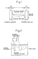
- Fig. 1 The potential difference distribution of an electrolytic reaction relating to surface treatment using an external power supply is as shown in Fig. 1 between two electrodes (namely an anode and cathode (working electrode)).
- Fig. 1 when a voltage is applied between the two electrodes, the voltage distribution is divided into two parts as shown in this drawing. Namely, the voltage between the two electrodes is divided into a potential difference at the electrode interface and a potential difference in the solution phase.
- Film formation in electrolytic treatment is carried out by causing the components dissolved in the solution to undergo an electrochemical reaction (oxidation reaction or reduction reaction) on the electrode (solid) surface due to this change in potential difference at the electrode interface. Namely, a film is formed by a reaction (interface reaction) at the electrode surface (interface).
- the change in the potential difference in the solution phase occurs as a result of a chemical reaction accompanying a change in the potential difference at the electrode interface, and is a reflection of the electrochemical equilibrium between chemical component ions in the solution phase.
- changes in potential difference in the solution phase do not reflect a chemical reaction resulting from electrolysis of solution phase components. Consequently, it is essential that changes in the potential difference in the solution phase be of an extremely low voltage and do not cause a phase transition (solution ⁇ solid) accompanying chemical reaction.
- Electrolytic surface treatment pertaining to film formation, a solution phase reaction is a detrimental reaction.
- electrolytic phosphate chemical treatment sludge forms if a solution phase reaction occurs.
- Electrolytic surface treatment that is already used practically employs contrivances such that only the interface reaction is allowed to occur while the solution phase reaction is not. Namely, actions are taken so that all of the electrical energy (voltage, current) applied to the electrolytic treatment system acts only on the electrode interface.
- the object of the present invention is to improve the efficiency of the electrolytic phosphate chemical treatment reaction.
- the means for achieving this is basically similar to other electrolytic surface treatment, consisting of preventing a reaction in the solution phase (solution phase reaction) and improving the efficiency of the reaction (interface reaction) at the electrode surface (interface).
- a means that is unique to electrolytic phosphate chemical treatment is required for the specific means for achieving this.
- a first means is preventing the reaction in the solution phase (solution phase reaction).
- cationic electrodeposition coating which is another electrolytic surface treatment that is used practically, the solute component is an organic substance, and a complex cannot be used in the manner of electroplating. Consequently, accommodations must be made using a different method.
- the electrodeposition coating liquid is a solution in which an organic substance is dispersed. Moreover, the anode in cationic electrodeposition coating is insoluble.
- preventing the solution phase reaction means maintaining the coating liquid in a state in which organic substances are dispersed. If the coating liquid is unable to be maintained in a state in which organic substances are dispersed, the coating liquid aggregates resulting in the formation of solids. Namely, the solution phase reaction proceeds.
- Actions are taken for electrodeposition coating so that a solution state can be maintained at all times. More specifically, these actions consist of controlling the temperature at a constant temperature, preventing contamination by Na ions and other impurities, and constantly filtering and circulating the coating liquid to prevent the decomposition and separation of organic substances of the solution components, including solids. Since these actions are taken, electrodeposition coating is able to maintain a solution state at all times and prevent reactions in the solution phase.
- a voltage is applied between electrodes of an electrolysis liquid controlled in this manner, that voltage does not act in the solution phase. Changes in the potential difference of the applied voltage act only at the electrode surface, and an electrodeposition coating film precipitates on the surface of the cathode (working surface).
- a second means of improving electrolytic phosphate chemical treatment reaction efficiency consists of improving the reaction efficiency at the electrode surface (interface).
- electrolytic phosphate treatment involves electrolytic surface treatment using water for the solvent, the following clarifies differences with other electrolytic treatment (such as electroplating and electrodeposition coating) that similarly use water for the solvent.
- electrolytic phosphate chemical treatment cathodic treatment
- the gas that is generated from the treatment bath differs from conventional electrolytic treatment (e.g., electroplating and electrodeposition coating). This is illustrated in Table 2.
- Electrolytic Treatment and Reaction Components Solvent (water) Solute Hydrogen gas (H 2 ) Oxygen gas (O 2 ) Film components Non-film components
- Electroplating O formed) O (formed) O (formed) X (not formed)
- Electrolytic phosphate chemical treatment O (formed) O (formed) O (formed) O (formed: nitrogen oxides)
- the gas that is generated from the treatment bath is only hydrogen gas and oxygen gas resulting from electrolysis of water.
- electrolytic phosphate chemical treatment in addition to hydrogen and oxygen, there are also nitrogen oxides generated by decomposition of NO 3 - , a solute component.
- the states of these nitrogen oxides consist of NO, NO 2 and N 2 O 4 , and their boiling points at atmospheric pressure differ considerably. Differences in Boiling Points at Atmospheric Pressure NO: -151°C NO 2 : 21.15°C H 2 : -252°C N 2 O 4 : 29.07°C O 2 : -182°C
- Table 3 shows a comparison of the boiling points of each gas at atmospheric pressure.
- the gas generated in the electrolysis reaction consists only of hydrogen gas and oxygen gas as a result of electrolysis of the solvent in the form of water as shown in Table 2.
- the boiling points of hydrogen and oxygen are extremely low as shown in Table 3. This indicates that both hydrogen and oxygen are easily evaporated and removed from the treatment bath.
- the gases generated in electrolytic phosphate chemical treatment consist of nitrogen oxide gas (N 2 O 4 , NO 2 and NO) in addition to hydrogen gas and oxygen gas as shown in Table 2. It is clear that the ease by which this gas is removed from the treatment bath differs depending on the state of this nitrogen oxide gas (N 2 O 4 , NO 2 and NO). Namely, whether the nitrogen oxide gas generated is in the form of N 2 O 4 and NO 2 or NO results in a considerable difference in the conditions by which the gas is removed from the treatment bath. If the gas that is generated can be limited only to NO, the reaction (interface reaction) at the electrode surface (interface) is thought to be able to be maintained at the level of electroplating. However, if the gas that is generated contains N 2 O 4 and NO 2 , that gas cannot be easily removed from the treatment bath, and it is therefore presumed that the reaction efficiency at the electrode surface (interface) would decrease.
- a decrease in the reaction efficiency at the electrode surface (interface) is presumed to cause a decrease in adherence between the film and article to be treated.
- limiting the gas generated to NO only is required for electrolytic phosphate chemical treatment, and the present invention provides a specific method for accomplishing this.
- the solution phase reaction is not affected by the application of voltage and current by an external power supply in the case of fundamental electrolytic surface treatment. This should also be observed in electrolytic phosphate chemical treatment as well.
- conventional non-electrolytic phosphate chemical treatment forms a film by using a solution phase reaction (see Fig. 8).
- Electrochemical equilibrium reactions that have the possibility of occurring in the solution phase of an electrolytic phosphate chemical treatment bath are shown in Table 4. Electrochemical Equilibrium Reactions that can Occur in the Solution Phase Dissociation of phosphoric acid H 3 PO 4 ⁇ H + + H 2 PO 4 - (1) H 2 PO 4 - ⁇ 2H + + PO 4 3- (2) Fe 2+ /Fe 3+ Fe 2+ ⁇ Fe 3+ + e - (0.77 V) (3)
- the reactions of (1) through (3) in Table 4 are essential reactions in non-electrolytic treatment, and they take place in the solution phase in non-electrolytic treatment.
- the reactions of (1) through (3) are reactions that occur in non-electrolytic treatment. This means that the reactions of (1) through (3) occur due to factors other than the application of voltage and current to the treatment bath. Namely, they occur due to changes in the electrochemical conditions (pH, ORP, etc.) of the treatment bath.
- the electrochemical conditions of the treatment bath can be set to conditions under which the reactions of (1) through (3) do not proceed, in order to prevent the reactions of (1) through (3).
- the orthophosphoric acid ratio is 1 when the pH is 0, it is roughly 0.1 at pH 3 (see Ohki, M. and Tanaka, M. ed., Iwanami Koza Publishing, Modern Chemistry 9, Oxidation and Reduction of Acids and Bases, 1979, p. 75). Namely, the orthophosphoric acid ratio (H 3 PO 4 /H 2 PO 4 - ) decreases from 1 to 0.1 as the pH changes from 0 to 3.
- non-electrolytic treatment involves the formation of a film by reacting components in solution. Film formation takes place by dissociating phosphate ion to PO 4 3- and reacting with film forming metal ions (e.g., zinc ions). Consequently, in a non-electrolytic treatment bath, the composition consists mainly of H 2 PO 4 - to facilitate progression of dissociation of phosphate ions. Consequently, a bath consisting primarily of H 3 PO 4 at pH 2.5 or lower does not allow the formation of a film in non-electrolytic treatment. For this reason, the pH of a non-electrolytic treatment bath is roughly 3, and H 3 PO 4 /H 2 PO 4 - is controlled in the form of an acid ratio.
- the pH of the electrolytic treatment bath is 2.5 or lower, and more preferably pH 2 or lower.
- the pH be 2.5 or lower. This is because, if the pH of the treatment bath exceeds 2.5, the ratio of metal ions such as Zn and Mn, which form phosphate compounds by bonding with phosphate ions, to phosphoric acid (ions) becomes relatively large, thereby facilitating the formation of sludge.
- Fe ions dissolve in the treatment bath when a steel material is used as the article to be treated and when an Fe electrode is used for the film forming metal electrode in electrolytic chemical treatment.
- the dissolution of Fe proceeds in the manner of Fe ⁇ Fe 2+ ⁇ Fe 3+ , and dissolves and exists in the treatment bath in the state of Fe 2+ or Fe 3+ .
- the reaction of Fe 2+ ⁇ Fe 3+ + e - of (0.77 V) of formula (3) means that Fe ions can proceed in the dissolved state of Fe 2+ ⁇ Fe 3+ in solution only when the ORP (oxidation-reduction potential; hydrogen standard electrode potential) of the treatment bath is 0.77 V or higher. If the ORP of the treatment bath is less than 0.77 V, even if Fe ions in solution proceed in the manner of Fe 2+ ⁇ Fe 3+ , they are unable to exist in the dissolved state, and oxidized Fe 3+ solidifies. Namely, sludge forms in the phosphate chemical treatment bath.
- a voltage of about 10 V or less is preferably applied between the electrodes of the treatment bath.
- anodic electrolysis is carried out using a steel material for the anode
- cathodic electrolysis is carried out using an Fe electrode for the anode and an article to be treated for the cathode
- Fe dissolves in the treatment bath (Fe ⁇ Fe 2+ + 2e - ).
- Fe ions dissolve.
- a voltage of 10 V or less is applied between the electrodes in the treatment bath, dissolved Fe 2+ ions are further oxidized.
- Table 5 shows the main elementary electrochemical reactions at the electrode interface of electrolytic phosphate chemical treatment (in the case of cathodic treatment).
- a large change in the potential difference occurs at the electrode interface in electrolytic treatment. Consequently, ions that react at the electrode interface undergo a phase transition reaction accompanying a change in charge. Namely, ions soluble in water become a solid to form a film or become a gas and are removed from the solution at the electrode interface.
- the characteristic reactions of electrolytic phosphate chemical treatment consist of the nitrate ion reduction reaction of (ii) and the phosphoric acid dissociation and phosphate precipitation reaction. For this reason, controlling these two reactions at the electrode interface is considered to be an important factor for practical application of electrolytic phosphate chemical treatment.
- gas generated in the reduction reaction of nitrate ions is in the form of N 2 O 4 , NO 2 or NO.
- the boiling points of N 2 O 4 and NO 2 are quite different from NO.
- the gas that is generated be NO because of its low boiling point.
- the present invention divides the electrolytic phosphate chemical treatment reaction into an electrochemical reaction at the electrode interface and an electrochemical reaction in the solution phase, and then controls each reaction.
- the present invention is characterized by carrying out the elementary reactions from a solution to a solid (film) only in the form of an electrochemical reaction at the electrode interface.
- the elementary reactions in which a film is formed from a solution consist of two types of reactions at the cathode interface. These consist of (1) reduction and precipitation reaction of metal ions, and (2) dissociation of phosphoric acid and a precipitation reaction of phosphate crystals. In order to carry out the two types of reactions at the cathode interface only, it is necessary to maintain the solution phase in the state of a solution only.
- the ORP of the treatment bath is maintained at 700 mV or higher, and preferably 770 mV or higher.
- the ORP of the treatment bath is selected to be 800 mV or higher, and more preferably 840 mV or higher. The following is a description of a specific method for maintaining the ORP of the treatment bath at 700 mV or higher. There are two methods for accomplishing this.
- Fe ions are recognized to be involved in the film formation reaction in the electrolytic phosphate chemical treatment of the present invention.
- the reasons for Fe ions dissolving in the treatment bath consist of dissolution in the case the article to be treated in anodic treatment is steel, dissolution from the Fe electrode in cathodic treatment, and dissolution from the Fe electrode when treatment is dormant.
- Control of the amount of Fe electrolysis from the article to be treated and Fe electrode during treatment can be performed by controlling the voltage and current applied. Control of the amounts of this electrolysis can be performed if the amount of electrolysis is roughly 0.1 A/dm 2 or less for both anodic and cathodic electrolysis.
- dormant electrolysis described in Japanese Unexamined Patent Publication No. 2000-234200 can be carried out for electrolysis from the Fe electrode while treatment is dormant.
- dormant electrolysis refers to suppressing the dissolution of Fe while treatment is dormant by using a metal that is insoluble in the treatment bath (such as titanium) for the anode, using an Fe electrode for the cathode, and applying a voltage of 2-5 V.
- Replenishment and formation of Fe-phosphoric acid complex involves replenishment of Fe 3+ ions in the form of a chemical preliminarily in the form of a stable (inactive) complex and not in the form of free (active) ions.
- the formation of a complex (Fe 3+ -H 3 PO 4 ) by Fe 3+ ions and phosphoric acid is well known.
- the reactivity of the Fe 3+ ions decreases if a complex is formed.
- the addition and dissolution of Fe ions to the treatment bath in the form of a phosphoric acid complex means that the process of Fe 2+ ⁇ Fe 3+ + e - and its reverse process are omitted simultaneous to free Fe ions (Fe 2+ or Fe 3+ ) being supplied to the treatment bath (solution phase). Consequently, the treatment bath includes a state in which Fe 3+ dissolved in the form of a complex is in a stable state.
- a replenishing liquid containing Fe-phosphoric acid complex is carried out by dissolving iron nitrate in a orthophosphoric acid solution.
- Actual replenishing liquids also contain Zn 2+ , Ni 2+ , NO 3 - and so forth in addition to Fe3+.
- the present invention requires that the ORP of the electrolytic phosphate chemical treatment bath be maintained within a suitable range for film formation.
- Reactable treatment bath components of the electrolytic phosphate chemical treatment bath decrease accompanying film formation.
- the decrease in reactable components results in a decrease in reactivity and a decrease in the ORP of the treatment bath. Consequently, ORP is adjusted by replenishing the bath with a chemical containing reactable components.
- the ORP of the treatment bath can be suitably maintained as a general rule by maintaining a balance between the amount of electrolysis for forming a film and the replenishment with chemical.
- Chemical replenishment of the treatment bath of the present invention is carried out by replenishing a chemical having basically the same chemical components as the treatment bath corresponding to the film that is formed so as to minimize fluctuations in the treatment bath composition according to addition and treatment of the article to be treated.
- the pH of a typical replenishing chemical is lower than the pH of the treatment bath. Namely, the active hydrogen concentration of the replenishing chemical is greater. Consequently, when replenishing chemical is added, it tends to act in a direction that lowers the pH of the treatment bath, which is turn causes an increase in the ORP of the treatment bath.
- the concentration of active hydrogen ion contained in the replenishing chemical can also be suppressed in order to suppress an increase in the ORP of the treatment bath.
- the dissociated state of H 3 PO 4 is controlled even if the composition of H 3 PO 4 contained in the replenishing chemical is the same. Namely, although orthophosphoric acid exists in the equilibrium state of H 3 PO 4 /H 2 PO 4 - , that state is shifted to the higher concentration of H 2 PO 4 - .
- the addition of such a replenishing chemical makes it possible to control increases in the ORP of the treatment bath.
- the filtration and circulation paths of the treatment bath are basically open, and as a means of separating the NO 2 , N 2 O 4 and/or NO gas formed in the treatment bath accompanying electrolytic treatment from the treatment bath, by separating the treatment tank into an electrolytic treatment tank that performs electrolytic treatment and an auxiliary tank that does not perform electrolytic treatment, circulating the treatment bath between the two tanks, and providing a mechanism for exposing the treatment liquid to the atmosphere, NO 2 , N 2 O 4 and/or NO gas generated and dissolved in the electrolytic treatment tank is removed.
- a mechanism that removes nitrogen oxides formed in the treatment bath accompanying electrolytic treatment in a circulation system in which treatment bath subjected to electrolytic treatment in the electrolytic treatment tank returns to said electrolytic treatment tank via a circulation pump and filter.
- This mechanism is basically a system that opens the filtration and circulation systems of the treatment bath to the atmosphere.
- the treatment bath In a system in which the filtration and circulation systems are closed, the treatment bath is in a pressurized state within the system. In the pressurized state, it is difficult for gases dissolved in the treatment bath to escape from solution. If a mechanism is employed that opens the filtration and circulation systems to the atmosphere, namely a mechanism is employed that reduces pressure, dissolved gases can easily escape from solution.
- a mechanism that is permeable to treatment liquid which allows the passage of membranous and other solid structures in the above auxiliary tank that does not perform electrolytic treatment, and for example, a filter having a mechanism that filters treatment liquid is used as the auxiliary tank.
- a mechanism is provided for the mechanism that facilitates escape of gases that extracts a portion of the treatment liquid prior to being led into a filter cloth or other filtration material and exposes it to the atmosphere in the above filter.
- the treatment bath is maximally pressurized in front of the filtration material of the filter. Under these maximally pressurized conditions, gases dissolved in the treatment bath are pushed out of solution and aggregated on the cloth. If a portion of the solution under these aggregated conditions is extracted and exposed to the atmosphere, the aggregated gases are rapidly released into the atmosphere.
- the filter together with having the function of removing sludge, also has the function of capturing nitrogen oxide gas (NOx) dissolved in the solution.
- This function consists of precipitating dissolved gas (NOx) onto a filter cloth by allowing the solution to pass through the filter cloth. This action is for allowing the filter cloth to act catalytically on removal of gas.
- N 2 O 4 (g) represents the intermediate process of that decomposition
- NO (g) represents the final decomposed form. Namely, decomposition of NO 3 - proceeds in the manner of NO 3 - ⁇ N 2 O 4 (g) ⁇ NO (g). This reduction reaction of NO 3 - results in an increase in volume due to this reaction (from a liquid to a gas).
- the decomposition reaction of NO 3 - follows formula (12).
- the ORP of the treatment bath is 960 mV or lower, the reaction can proceed according to formula (12).
- the decomposition reaction of NO 3 - only proceeds according to formula (12), and by providing a mechanism for venting gas from the lines, that can be easily achieved.
- a preferable mode of the present invention can be achieved by making the filtration and circulation system of the treatment bath an open system.
- a preferable mode of the present invention provides a mechanism that removes NOx gas generated in the treatment bath accompanying electrolytic treatment in a circulation system in which treatment bath subjected to electrolytic treatment in an electrolytic treatment tank is returned to said electrolytic treatment tank via a circulation pump and filter.
- the mechanism that removes NOx gas preferably extracts a portion of the treatment liquid prior to being led into the filtering material of the filter, exposes it to the atmosphere and removes NOx gas followed by returning it to said treatment tank by a liquid circulation path.
- the ORP of said treatment bath is made to be 800 mV or higher, and preferably 840 mV or higher, and gas formed as a result of decomposition of NO 3 - in the treatment bath is preferably only in the form of NO (g).
- the reaction of formula (19) is a reaction that is not accompanied by a phase transition within the solution phase.
- the reaction of formula (19) means that, if the ORP of the treatment bath is 840 mV or lower, the possibility exists of NO 3 - in the solution changing to NO 2 - . Such a change in the treatment bath is harmful with respect to the stability of the treatment bath. For this reason, maintaining the ORP of the treatment bath above 840 mV is preferable for preventing the reaction of formula (19).
- each of the steps of degreasing, rinsing, rinsing, electrolytic phosphate chemical treatment and rinsing are carried out using a tank having a volume of 200 liters.
- the degreasing step is performed by immersing for 4-5 minutes using an alkaline degreaser at a prescribed concentration and temperature.
- the rinsing step is carried out until the degreaser and other chemicals are completely removed from the article to be treated.
- Electrodeposition coating is performed so that the coated film thickness after baking is 15-25 ⁇ m, using the Power Top U-56 manufactured by Nippon Paint Co., Ltd.
- the volume of the electrolytic treatment bath is 200 liters.
- the treatment bath was circulated 6-10 times per hour using a filter to ensure the transparency of the treatment bath.
- eight sets of automobile air-conditioner parts (clutch, stator housing) used in this experiment per hanger (treatment jig) were treated in the treatment bath. This is depicted in Fig. 3.
- reference symbol 1 indicates a 200 liter treatment bath, 2 a power supply, 3 an electrode, 4 a stator housing (article to be treated), 5 a filter, 6 a pump, 7 a sensor tank (pH electrode, ORP electrode, etc.) and 8 a controller.
- the automobile air-conditioner part (clutch, stator housing) shown in Fig. 4 was used as the article to be treated in the examples and comparative examples.
- the stator housing of Fig. 4 consists of welding and joining a plate 20 (press stamped part) that serves as a flat surface, and a housing that serves as outer peripheral portion 21 (press formed part).
- the housing serving as the outer peripheral portion is made by deforming a flat plate to an irregular structure by press forming. For this reason, the outer peripheral portion is a surface that is greatly deformed in press forming.
- Lubricating oil strongly adheres to the greatly deformed surface during press forming. This strongly adhered lubricating oil inhibits the phosphate chemical treatment reaction.
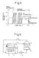
- Electrolytic phosphate chemical treatment was carried out with the electrolysis method shown in Fig. 5.
- Electrolytic treatment consisted of cathodic electrolysis and anodic electrolysis.
- Cathodic electrolysis consisted of initially performing 13 rounds of pulsed electrolysis using an Ni electrode and subsequently performing continuous electrolysis using an Ni electrode and Fe electrode. Details of the electrolysis conditions in the examples and comparative examples are shown in the following table (Table 8). Furthermore, the amount of Fe electrolysis shown in Table 8 is the amount of Fe electrolysis when the effective surface area of the article to be treated is 2 dm 2 /piece.
- Electrolysis conditions (per 8 hous-ings) Anodic electrolysis Cathodic electrolysis Fe Cathodic electrolysis Ni Ex. 1 10 V x 0.6 A x rising for 1 sec., holding for 21 sec. (Amt. of Fe electrolysis: 0.04 A/dm 2 ) Dormant for 42 sec., 10 V x 0.6 A x rising for 20 sec., holding for 35 sec. (Amt. of Fe electrolysis: 0.04 A/dm 2 ) 1.12 V x 30 A (dormant for 1 sec., rising for 2 sec.) x 13 times 2.10 V x 20 A, rising for 15 sec., holding for 43 sec. Ex. 2 8 V x 0.1 A x rising for 2 sec., holding for 6 sec. (Amt.
- the article to be treated was subjected to electrodeposition coating in the steps following the chemical treatment of Table 6. Following electrodeposition coating, a coating corrosion resistance evaluation test was performed on the article to be treated. The coating corrosion resistance evaluation test was performed by making scratches in the coating extending to the substrate with a knife in the flat surface portion and outer peripheral portion of the article to be treated, and immersing it for 240 hours in a 5% sodium chloride solution at 55°C. After 240 hours of immersion had elapsed, the article to be treated was rinsed with water and dried by allowing it to stand for at least 2 hours, followed by affixing adhesive tape to the coated surface that was scratched with the knife and then peeling off the tape with considerable force.
- the treatment baths of the comparative examples both had an ORP of about 260 mV (Ag/AgCl electrode), and this is equivalent to a potential based on the hydrogen standard potential of about 470 mV, which does not fall within the present invention.
- Example 1 Example 2
- Example 3 Comp. Ex. 1 Comp. Ex. 2 During treatment None None None None None None 3 days after treatment None None None Formed Formed
- Example 1 is the standard method of the present invention. The amount of Fe electrolysis is controlled and the standard chemical is used. For this reason, there is no formation of sludge in the treatment bath even after standing.
- Example 2 is an example of the present invention in the case of using a replenishing chemical containing Fe ions.
- Example 3 is an example of the present invention showing the use of a chemical in which the degree of dissociation of phosphoric acid has been adjusted for the replenishing chemical in order to lower the ORP of the treatment bath. Furthermore, the same chemical as in Example 1 is used starting in the 61 st round of treatment in Example 3. This is done for the purpose of raising the ORP again after it has lowered.
- Comparative Example 1 is an example of an increased amount of Fe electrolysis and a lowered ORP of the treatment bath.
- the amount of Fe electrolysis is 0.15 A/dm 2 , which is larger than that of the examples.
- the filtration and circulation path is an open system composed with lines as shown in Fig. 6 (Example 4) or a closed system composed with lines as shown in Fig. 7 (Example 5).
- reference symbol 9 indicates a hanger, 10 a filter cloth, and 11 an article to be treated.
- pressure reducing open line 13 is also provided in the open system of Fig. 6, in addition to main circulation line 12, pressure reducing open line 13 is also provided. Gas dissolved in the solution is discharged from this pressure reducing open line 13.
- each step is carried out by a series of equipment in a tank having a volume of 1000 liters.
- the article to be treated is immersed for 110 seconds and then moved to the next step in 40 seconds.
- An alkaline degreaser at a prescribed concentration and temperature is used in the degreasing steps.
- the electrolytic treatment bath is circulated 3-12 times per hour with a filtration circulation pump.
- the treatment hanger is used during treatment by attaching 30 automobile air-conditioner parts in the form of the article to be treated shown in Fig. 4 per side, or 60 parts on both sides, to each hanger. Electrodeposition coating is performed so that the coated film thickness after baking is 15-25 ⁇ m, using the Power Top U-56 manufactured by Nippon Paint Co., Ltd.
- Electrolytic phosphate chemical treatment was carried out according to the method of Fig. 5. This treatment was performed for 110 seconds/cycle-hanger, after which the hanger was moved to the next tank in 40 seconds. Thus, treatment for 110 seconds was repeated every 150 seconds. Electrolytic treatment was carried out in the order of anodic electrolysis followed by cathodic electrolysis. Cathodic electrolysis consisted of initially performing 8 rounds of pulsed electrolysis using an Ni electrode and subsequently performing continuous electrolysis using an Ni electrode and Fe electrode. The details of these electrolysis conditions are shown in Table 13. Electrolysis conditions (per 60 work pieces) Anodic electrolysis Cathodic electrolysis Fe Cathodic electrolysis Ni Examples 4 and 5 5 V x 0.1 A x rising for 1 sec., holding for 8 sec.
- the values indicated for ORP in Table 14 are shown based on an Ag/AgCl electrode serving as the ORP electrode used in the experiment apparatus.
- the values indicated with the Ag/AgCl electrode can be converted to potential values based on the hydrogen standard electrode potential serving as the indicated value of the present invention by adding 210 mV to those values.
- Status of Phosphate Chemical Treatment Bath (Mean Values) Treatment bath composition (g/L) Chem. anal. Values Treatment bath electrochemical conditions Phosphate ion Nitrate ion Nickel ion Zinc ion Total acidity (Pt) pH ORP Ag/ AgCl electrode potential Temp. (°C) Ex. 4 12.2 46 17.1 14.1 86 1.23 674 30 Ex. 5 7.69 31.5 12 8.99 54 2.48 597 33
- Example 5 the pH was higher, ORP was lower and concentrations of treatment bath components were lower than in Example 4. This indicates that the filtration-circulation system is a closed system, and that the electrochemical reaction efficiency is inferior to an open system.
- the ORP of 597 mV indicates the possibility of the occurrence of the reaction of formula (19), which is one of the reactions in the solution phase (solution reaction) in the treatment bath.
- the potential based on the Ag/AgCl electrode of the reaction of formula (19) is 630 mV or less. NO 3 - + 2H + + 2e - ⁇ NO 2 - + H 2 O (0.84 V)
- Example 4 Flat surface portion 0 0 Outer peripheral portion 1 1
- Example 5 During treatment None None 3 days after treatment None Formed
- Examples 4 and 5 are examples of practical mass production systems. When applied to mass production equipment, it was confirmed that it is preferable to make different accommodations than those of Examples 1-3 using experimental systems. Namely, since the treatment volume is continuous and large, the removal of NOx gas, which was able to be ignored in the experimental systems, is important. The difference between Examples 4 and 5 is the presence or absence of removal of NOx gas. This difference between the two was manifest in their respective treatment baths. Namely, if NOx gas is not removed, the concentration of NOx gas in the treatment bath does not decrease, and this acts in the direction of inhibiting the reduction reaction of NO 3 - , with the reaction of formula (19) coming to act as the solution reaction.
- the present invention was shown in principle to be able to substantially eliminate sludge.
- variations exist in the contents of the treatment bath.
- the ORP in the treatment bath should be raised and maintained at 840 mV or higher. If this is done, sludge formation can be substantially reduced to zero, with the exception of minor variations.
- the electrochemical reactions accompanying phase transitions relating to film formation can be limited to only electrochemical reactions at the electrode interface by substantially eliminating sludge formation.
- the decomposition reaction of NO 3 - at the electrode interface can be made to consist only of formula (12), thereby making it possible to improve electrolysis reaction efficiency. Consequently, the film that is formed can be formed reliably adhered to the article to be treated. For this reason, in the case of a coating substrate, a film can be formed having a coating corrosion resistance superior to cases in which sludge is formed.
Landscapes
- Chemical & Material Sciences (AREA)
- Engineering & Computer Science (AREA)
- Chemical Kinetics & Catalysis (AREA)
- Electrochemistry (AREA)
- Materials Engineering (AREA)
- Metallurgy (AREA)
- Organic Chemistry (AREA)
- Automation & Control Theory (AREA)
- Chemical Treatment Of Metals (AREA)
- Water Treatment By Electricity Or Magnetism (AREA)
Applications Claiming Priority (4)
| Application Number | Priority Date | Filing Date | Title |
|---|---|---|---|
| JP2001049017 | 2001-02-23 | ||
| JP2001049017 | 2001-02-23 | ||
| JP2002020568A JP4019723B2 (ja) | 2001-02-23 | 2002-01-29 | 電解リン酸塩化成処理方法 |
| JP2002020568 | 2002-01-29 |
Publications (1)
| Publication Number | Publication Date |
|---|---|
| EP1234896A1 true EP1234896A1 (de) | 2002-08-28 |
Family
ID=26610027
Family Applications (1)
| Application Number | Title | Priority Date | Filing Date |
|---|---|---|---|
| EP02003269A Withdrawn EP1234896A1 (de) | 2001-02-23 | 2002-02-21 | Elektrolytisches phosphatchemisches Behandlungsverfahren |
Country Status (8)
| Country | Link |
|---|---|
| US (1) | US7833404B2 (de) |
| EP (1) | EP1234896A1 (de) |
| JP (1) | JP4019723B2 (de) |
| KR (1) | KR100491178B1 (de) |
| CN (1) | CN1247826C (de) |
| BR (1) | BR0200467B1 (de) |
| CA (1) | CA2372730C (de) |
| MX (1) | MXPA02001937A (de) |
Families Citing this family (14)
| Publication number | Priority date | Publication date | Assignee | Title |
|---|---|---|---|---|
| JP3937957B2 (ja) | 2002-07-22 | 2007-06-27 | 株式会社デンソー | 電解リン酸塩化成処理浴から有効成分を回収する方法 |
| JP2005023422A (ja) * | 2003-06-09 | 2005-01-27 | Nippon Paint Co Ltd | 金属表面処理方法及び表面処理金属 |
| JP4419905B2 (ja) * | 2005-04-28 | 2010-02-24 | 株式会社デンソー | 電解リン酸塩化成処理方法 |
| JP4419968B2 (ja) * | 2005-07-15 | 2010-02-24 | 株式会社デンソー | 電解リン酸塩化成処理方法ならびに温間もしくは熱間鍛造加工方法 |
| KR100729438B1 (ko) | 2006-09-21 | 2007-06-15 | (주)천우테크 | 부동태용 인산염젤 |
| CN101555616B (zh) * | 2009-05-13 | 2012-11-07 | 大连理工大学 | 镍钛合金表面羟基磷灰石/二氧化钛复合涂层的制备方法 |
| JP2012021177A (ja) * | 2010-07-12 | 2012-02-02 | Denso Corp | 電解リン酸塩化成処理法 |
| JP5278391B2 (ja) * | 2010-07-16 | 2013-09-04 | 株式会社デンソー | 電解リン酸塩化成処理方法 |
| GB201121128D0 (en) | 2011-12-08 | 2012-01-18 | Dow Corning | Treatment of filler with silane |
| GB201121124D0 (en) | 2011-12-08 | 2012-01-18 | Dow Corning | Hydrolysable silanes |
| GB201121122D0 (en) | 2011-12-08 | 2012-01-18 | Dow Corning | Hydrolysable silanes and elastomer compositions containing them |
| GB201121133D0 (en) | 2011-12-08 | 2012-01-18 | Dow Corning | Hydrolysable silanes |
| WO2014188488A1 (ja) * | 2013-05-20 | 2014-11-27 | 貴和化学薬品株式会社 | 電解リン酸塩化成処理浴組成物及びリン酸塩化成処理方法 |
| KR102005521B1 (ko) * | 2018-11-23 | 2019-07-30 | 그린화학공업(주) | 전해 인산염 피막처리 멀티 트랙 시스템 및 이를 이용한 전해 인산염 피막처리 방법 |
Citations (3)
| Publication number | Priority date | Publication date | Assignee | Title |
|---|---|---|---|---|
| US4565585A (en) * | 1983-08-19 | 1986-01-21 | Nippondenso Co., Ltd. | Method for forming a chemical conversion phosphate film on the surface of steel |
| EP0597131A1 (de) * | 1992-04-30 | 1994-05-18 | Nippondenso Co., Ltd. | Phosphatierungsverfahren |
| EP1074640A1 (de) * | 1998-12-17 | 2001-02-07 | Denso Corporation | Elektrolytischer phosphatierungsprozess und kompositbeschichtungen, die auf eine stahloberfläche aufgebracht sind |
Family Cites Families (7)
| Publication number | Priority date | Publication date | Assignee | Title |
|---|---|---|---|---|
| JPH0718021B2 (ja) * | 1987-11-27 | 1995-03-01 | 日本電装株式会社 | リン酸塩化成処理液の電気伝導度制御方法 |
| DE58902702D1 (de) * | 1988-11-25 | 1992-12-17 | Metallgesellschaft Ag | Verfahren zum aufbringen von phosphatueberzuegen. |
| JP2739864B2 (ja) * | 1991-05-01 | 1998-04-15 | 株式会社デンソー | リン酸塩化成処理方法 |
| US5645706A (en) * | 1992-04-30 | 1997-07-08 | Nippondenso Co., Ltd. | Phosphate chemical treatment method |
| JP2000160394A (ja) * | 1998-12-01 | 2000-06-13 | Nippon Parkerizing Co Ltd | 鉄系金属材料の短時間りん酸塩処理方法 |
| JP3678096B2 (ja) * | 1998-12-17 | 2005-08-03 | 株式会社デンソー | 電解リン酸塩化成処理方法及び鉄鋼表面に形成される複合皮膜の形成方法 |
| JP3937957B2 (ja) * | 2002-07-22 | 2007-06-27 | 株式会社デンソー | 電解リン酸塩化成処理浴から有効成分を回収する方法 |
-
2002
- 2002-01-29 JP JP2002020568A patent/JP4019723B2/ja not_active Expired - Lifetime
- 2002-02-20 US US10/077,777 patent/US7833404B2/en not_active Expired - Fee Related
- 2002-02-21 EP EP02003269A patent/EP1234896A1/de not_active Withdrawn
- 2002-02-21 BR BRPI0200467-4A patent/BR0200467B1/pt active IP Right Grant
- 2002-02-22 KR KR10-2002-0009562A patent/KR100491178B1/ko not_active Expired - Lifetime
- 2002-02-22 CN CNB02105245XA patent/CN1247826C/zh not_active Expired - Lifetime
- 2002-02-22 CA CA002372730A patent/CA2372730C/en not_active Expired - Lifetime
- 2002-02-22 MX MXPA02001937A patent/MXPA02001937A/es active IP Right Grant
Patent Citations (3)
| Publication number | Priority date | Publication date | Assignee | Title |
|---|---|---|---|---|
| US4565585A (en) * | 1983-08-19 | 1986-01-21 | Nippondenso Co., Ltd. | Method for forming a chemical conversion phosphate film on the surface of steel |
| EP0597131A1 (de) * | 1992-04-30 | 1994-05-18 | Nippondenso Co., Ltd. | Phosphatierungsverfahren |
| EP1074640A1 (de) * | 1998-12-17 | 2001-02-07 | Denso Corporation | Elektrolytischer phosphatierungsprozess und kompositbeschichtungen, die auf eine stahloberfläche aufgebracht sind |
Also Published As
| Publication number | Publication date |
|---|---|
| KR100491178B1 (ko) | 2005-05-24 |
| BR0200467B1 (pt) | 2013-04-09 |
| US7833404B2 (en) | 2010-11-16 |
| CN1381616A (zh) | 2002-11-27 |
| CA2372730A1 (en) | 2002-08-23 |
| US20020162752A1 (en) | 2002-11-07 |
| CN1247826C (zh) | 2006-03-29 |
| KR20020069167A (ko) | 2002-08-29 |
| JP4019723B2 (ja) | 2007-12-12 |
| MXPA02001937A (es) | 2004-08-12 |
| JP2002322593A (ja) | 2002-11-08 |
| CA2372730C (en) | 2006-11-07 |
| BR0200467A (pt) | 2002-10-29 |
Similar Documents
| Publication | Publication Date | Title |
|---|---|---|
| US7833404B2 (en) | Electrolytic phosphate chemical treatment method | |
| EP2054539B1 (de) | Verfahren zur abscheidung von chromschichten als hartverchromung, galvanisierungsbad sowie hartverchromte oberflächen | |
| US10738383B2 (en) | Method for nickel-free phosphating metal surfaces | |
| JP3455709B2 (ja) | めっき方法とそれに用いるめっき液前駆体 | |
| US20010054557A1 (en) | Electroplating of metals using pulsed reverse current for control of hydrogen evolution | |
| Hine et al. | On the oxidation of cyanide solutions with lead dioxide coated anode | |
| WO2015121790A2 (es) | Proceso de cromado trivalente continuo | |
| US4144149A (en) | Method for working up aqueous residues from metallizing baths | |
| Snyder | Decorative chromium plating | |
| KR100400522B1 (ko) | 전해 인산염 화성처리 방법 및 철강표면에 형성된 복합피막 | |
| JPH09195083A (ja) | ハロゲン錫組成物及び電解メッキ方法 | |
| JP3678096B2 (ja) | 電解リン酸塩化成処理方法及び鉄鋼表面に形成される複合皮膜の形成方法 | |
| US6884332B2 (en) | Method and apparatus for treating an aqueous electroplating bath solution | |
| WO2005014890A1 (en) | An electrolyte solution | |
| JP3937957B2 (ja) | 電解リン酸塩化成処理浴から有効成分を回収する方法 | |
| KR20020061542A (ko) | 금속 표면-처리 방법 | |
| US20110272285A1 (en) | Method for the electrolytic deposition of chromium and chromium alloys | |
| EP2384800A1 (de) | Regeneration alkalischer Zinknickelelektrolyte durch Entfernen von Cyanidionen | |
| JP3179721B2 (ja) | 放電電解加熱による廃水処理方法及び装置 | |
| JPS61166999A (ja) | 鋼板の表面清浄方法 | |
| JP2005344208A (ja) | 無電解ニッケルめっき液の処理方法 | |
| CN110965086A (zh) | 一种酸性镀锌除杂剂及其应用 | |
| JPH11262641A (ja) | 無電解ニッケルめっき液再生用分離膜及び無電解ニッケルめっき液再生法 | |
| KR20210014587A (ko) | 금속성 기재의 부동태화 방법 | |
| HK1136010A (en) | Method for deposition of chromium layers as hard-chrome plating, electroplating bath and hard-chrome surfaces |
Legal Events
| Date | Code | Title | Description |
|---|---|---|---|
| PUAI | Public reference made under article 153(3) epc to a published international application that has entered the european phase |
Free format text: ORIGINAL CODE: 0009012 |
|
| AK | Designated contracting states |
Kind code of ref document: A1 Designated state(s): AT BE CH CY DE DK ES FI FR GB GR IE IT LI LU MC NL PT SE TR |
|
| AX | Request for extension of the european patent |
Free format text: AL;LT;LV;MK;RO;SI |
|
| 17P | Request for examination filed |
Effective date: 20021010 |
|
| 17Q | First examination report despatched |
Effective date: 20030305 |
|
| AKX | Designation fees paid |
Designated state(s): DE FR GB IT SE |
|
| STAA | Information on the status of an ep patent application or granted ep patent |
Free format text: STATUS: THE APPLICATION IS DEEMED TO BE WITHDRAWN |
|
| 18D | Application deemed to be withdrawn |
Effective date: 20150310 |