EP1234917A1 - Robinetterie sanitaire - Google Patents
Robinetterie sanitaire Download PDFInfo
- Publication number
- EP1234917A1 EP1234917A1 EP01104765A EP01104765A EP1234917A1 EP 1234917 A1 EP1234917 A1 EP 1234917A1 EP 01104765 A EP01104765 A EP 01104765A EP 01104765 A EP01104765 A EP 01104765A EP 1234917 A1 EP1234917 A1 EP 1234917A1
- Authority
- EP
- European Patent Office
- Prior art keywords
- valve
- housing
- closing body
- channel
- pressure
- Prior art date
- Legal status (The legal status is an assumption and is not a legal conclusion. Google has not performed a legal analysis and makes no representation as to the accuracy of the status listed.)
- Granted
Links
- 230000001960 triggered effect Effects 0.000 claims abstract 4
- 239000007788 liquid Substances 0.000 claims abstract 2
- 238000007789 sealing Methods 0.000 claims description 33
- XLYOFNOQVPJJNP-UHFFFAOYSA-N water Substances O XLYOFNOQVPJJNP-UHFFFAOYSA-N 0.000 claims description 20
- 238000009423 ventilation Methods 0.000 claims description 3
- 125000006850 spacer group Chemical group 0.000 claims description 2
- 235000013361 beverage Nutrition 0.000 claims 1
- 238000006073 displacement reaction Methods 0.000 claims 1
- 239000003651 drinking water Substances 0.000 description 6
- 235000020188 drinking water Nutrition 0.000 description 6
- 230000002093 peripheral effect Effects 0.000 description 5
- 238000000034 method Methods 0.000 description 3
- CURLTUGMZLYLDI-UHFFFAOYSA-N Carbon dioxide Chemical compound O=C=O CURLTUGMZLYLDI-UHFFFAOYSA-N 0.000 description 2
- 230000000881 depressing effect Effects 0.000 description 2
- 230000000994 depressogenic effect Effects 0.000 description 2
- 238000004512 die casting Methods 0.000 description 2
- 239000000463 material Substances 0.000 description 2
- 238000011144 upstream manufacturing Methods 0.000 description 2
- 238000004873 anchoring Methods 0.000 description 1
- 229910002092 carbon dioxide Inorganic materials 0.000 description 1
- 239000001569 carbon dioxide Substances 0.000 description 1
- 235000014171 carbonated beverage Nutrition 0.000 description 1
- 238000010276 construction Methods 0.000 description 1
- 230000001419 dependent effect Effects 0.000 description 1
- 230000035622 drinking Effects 0.000 description 1
- 238000001914 filtration Methods 0.000 description 1
- 238000003780 insertion Methods 0.000 description 1
- 230000037431 insertion Effects 0.000 description 1
- 238000004519 manufacturing process Methods 0.000 description 1
- 230000001105 regulatory effect Effects 0.000 description 1
- 230000003319 supportive effect Effects 0.000 description 1
- 239000008399 tap water Substances 0.000 description 1
- 235000020679 tap water Nutrition 0.000 description 1
- 238000013022 venting Methods 0.000 description 1
Images




Classifications
-
- E—FIXED CONSTRUCTIONS
- E03—WATER SUPPLY; SEWERAGE
- E03C—DOMESTIC PLUMBING INSTALLATIONS FOR FRESH WATER OR WASTE WATER; SINKS
- E03C1/00—Domestic plumbing installations for fresh water or waste water; Sinks
- E03C1/02—Plumbing installations for fresh water
- E03C1/04—Water-basin installations specially adapted to wash-basins or baths
-
- F—MECHANICAL ENGINEERING; LIGHTING; HEATING; WEAPONS; BLASTING
- F16—ENGINEERING ELEMENTS AND UNITS; GENERAL MEASURES FOR PRODUCING AND MAINTAINING EFFECTIVE FUNCTIONING OF MACHINES OR INSTALLATIONS; THERMAL INSULATION IN GENERAL
- F16K—VALVES; TAPS; COCKS; ACTUATING-FLOATS; DEVICES FOR VENTING OR AERATING
- F16K39/00—Devices for relieving the pressure on the sealing faces
- F16K39/02—Devices for relieving the pressure on the sealing faces for lift valves
- F16K39/022—Devices for relieving the pressure on the sealing faces for lift valves using balancing surfaces
-
- E—FIXED CONSTRUCTIONS
- E03—WATER SUPPLY; SEWERAGE
- E03C—DOMESTIC PLUMBING INSTALLATIONS FOR FRESH WATER OR WASTE WATER; SINKS
- E03C2201/00—Details, devices or methods not otherwise provided for
- E03C2201/40—Arrangement of water treatment devices in domestic plumbing installations
- E03C2201/45—Arrangement of water treatment devices in domestic plumbing installations for carbonated water
-
- Y—GENERAL TAGGING OF NEW TECHNOLOGICAL DEVELOPMENTS; GENERAL TAGGING OF CROSS-SECTIONAL TECHNOLOGIES SPANNING OVER SEVERAL SECTIONS OF THE IPC; TECHNICAL SUBJECTS COVERED BY FORMER USPC CROSS-REFERENCE ART COLLECTIONS [XRACs] AND DIGESTS
- Y10—TECHNICAL SUBJECTS COVERED BY FORMER USPC
- Y10T—TECHNICAL SUBJECTS COVERED BY FORMER US CLASSIFICATION
- Y10T137/00—Fluid handling
- Y10T137/9464—Faucets and spouts
Definitions
- the invention relates to a sanitary fitting with two different water qualities determined by each other separate outlet connection, into which two are separated from each other through a common valve body Guided channel systems open, with each channel system at least one functionally separate from the other Valve arrangement is provided and one for such Sanitary fitting suitable lift valve arrangement.
- Sanitary fittings of this type are known from EP-A-0 501 989 and DE-A-196 08 482. These sanitary fittings have three separate supply lines, on the one hand for cold and hot domestic water, with a common outlet for Mixed water and on the other hand a feed line for Drinking water arranged in an upstream Filter device and / or a separate apparatus for Carbon dioxide admixture has been processed.
- these prior publications show various constructive solutions, both a valve arrangement use where an actuator has a Lever movement and a rotational movement of a Closing body a continuous opening of the Exhaust duct causes. This has the disadvantage that especially when extracting under higher pressure standing, e.g. carbonated drinking water the actuation of the valve arrangement and metering the escaping amount of drinking water special care requires.
- there is the advantage that the pressure in the sewer system to be shut off is not significant affects the actuating force of the lever movement.
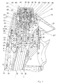
- Fig.1 shows, Sanitary fitting a column-like fitting housing 1, the is composed of several parts and a base part 3, a housing middle part 4 and a housing head 5 having.
- the base part 3 is screwed in Flange edge 37 of a lower connecting piece 2 closed and forms a lower one with it Stand area 6, which is to be in contact with an essentially horizontally running, not shown sink edge or a sink.
- the fixation of the Fitting housing 1 is made by clamping bracket by means of an external thread 7 of the Connection piece 2 screwable and attached to the Underside of the rim of the sink or the table top supportive mother.
- Housing inner connector 9 continues, which extends over a essential part of the middle housing part 4 extends and is therefore enclosed by it.
- a side Opening 10 in the housing stub 9 serves the lateral Leading out the hose 11 of a hose shower 12.
- the housing connector 9 carries in its upper Area one with it twist-proof by a radial Directed screw 13 connected lower mounting body 14, which together with an upper mounting body 19th forms an inner housing body 8.
- the lower Mounting body 14 is used to hold and attach a Valve seat body 15 of a valve assembly 17, the upper one Mounting body 19 for receiving an actuator 40 of this valve arrangement 17.
- the middle housing part 4 and the housing head 5 go laterally in a molded outlet connector 20,21 about.
- the lower outlet connection 20 runs obliquely above in order to e.g. by EP-A-0 447 777 known way of holding and guiding the Hose shower 12 to serve.
- the upper one, for processed Water provided outlet port 21 is obliquely downward directed so that the water is targeted into one held drinking vessel can be omitted.
- the housing base 3, the middle part 4 and the Housing head 5 are telescopically inserted into each other and are supported by the contact between rotating Paragraphs 22,23 and end faces 24,25 form-fitting to each other and are also by in these areas arranged sliding rings 26,27 and one 0-ring 28 rotatably supported against each other and sealed.
- the middle part of the housing is thus 4th between the housing base 3 and the housing head 5 axially fixed.
- the axial connection between the housing base 3 and the Housing head 5 takes place via the screw 13 on Fasten the housing base 3 or its housing socket 9 lower mounting body 14.
- a rotatability of the housing head 5th or its outlet connection 21 in a use-appropriate, variable position relative to the housing base 3 too ensure the lower and upper assembly body 14,19 rotatably connected to each other.
- they have to be adjacent to each other Radial surfaces 30.31 parallel grooves 32.33, in the two half-rings 34, 35 of U-shaped cross section from are inserted radially outside.
- One about this pushed-on sleeve 36 secures the half rings 34, 35 in the Grooves 32,33.
- valve construction assumes that the valve closing body 41 by the Valve seat body 15 is slidable to in a open valve position to be moved and accordingly its sealing position as shown in Fig.3 on a cylindrical inner surface 47 of the Valve seat body 15 occupies.
- Valve arrangement 17 accordinging to FIGS. 4 + 5
- Sealing position on an upstream inclined surface 48 of the Valve seat body 15 required, previously Valve closing body 41 together with the valve seat body 15 to be provided on the lower mounting body 14, so that its Connection to the associated actuating device 40 only with or after inserting the upper assembly body 19 can be done.
- the channel system 50 provided for process water Sanitary fitting is similar to Fig.1 of EP-A-0 447 777 shows by one through the connecting piece 2 led cold and hot water pipe 51.52 to one Mixing cartridge 53 are connected, one of which Mixed water line 54 through the connecting piece 2 after is led to over a below the Sanitary fitting hanging supply loop in the Hose 11 to open the hose shower 12.
- the mixing cartridge 53 is actuated from the outside by one on the side of the valve body 1, in the drawings on the back and therefore not visible in them Actuator consisting of a knob or a Lever exists.
- the one intended for treated water or drinking water Channel system 56 has one through the lower connection piece 2 introduced connecting line 57 to the funnel-shaped compensator housing 16 is connected.
- the position of the pressure compensator spindle-shaped regulating body 58 is by the Contact position on the conical inclined surface 59 one screwed laterally into the inner housing body 8 Set screw 60 determined. Lateral centering knobs 61 serve to secure the central position of the flow Regulators 58 in the funnel-shaped compensator housing 16. Since the pressure compensation is only for carbonated processed and accordingly under higher pressure of approx. 5 bar standing water or other carbonated water Drinks are required, the spindle-shaped Regulators 58 for only processed by filtering Water are omitted or removed.
- FIG. 1 shows two embodiments of FIG Lift valve having valve assembly 17. Since this have several similarities are the same Parts marked with the same numbers. A first one Exemplary embodiment is described below with reference to FIG and 3 explained in more detail.
- the housing 8 of the valve assembly 17 consists of a lower and upper housing body 14, 19, which have a Interlocking connection piece 42 interlock and through a 0-ring 43 provided on the connecting piece are mutually sealed.
- the arrangement provided lower housing body 14 to be able to they are in the axial direction to each other attached that they can be rotated against each other.
- two half-rings 34, 35 which are U-shaped in cross section and which inserted radially from the outside into circumferential grooves 32, 33 are.
- a sleeve pushed over the half rings 34, 35 36 secures them in this position. It is possible on the To waive sleeve 36 and, if necessary, the half rings 34, 35 form a self-locking snap.
- the valve seat body 15 is with the inner wall 49 of the lower housing body 14 screwed and between a inner paragraph 62 and the end face 63 of the Connection piece 42 included, so that he fixed together with the lower housing body 14 is held.
- the valve closing body 41 is elongated and tailored and forms one end with a sealing ring 64 cooperating closing part 65 while its other End forms a guide piston 66, of which one Valve stem 67 extends like a piston rod.
- This guide piston 66 of the valve closing body 41 and the valve stem 67 are stepped against each other Bores 68, 69 in the upper housing body 19 provided sealing body 70, so that this supported by sealing rings 71, 72, the valve chamber 73 seals outside.
- the sealing body 70 is with Thread engagement from the top of a central bore 74 of the upper housing body 19 and is included a shoulder surface 75 on a flat radial surface 76 the same.
- Operation button 44 attached by part of the upper mounting body 19 and from the head part 5 of the housing is enclosed so that it is easily accessible via this protrudes.
- the pressure of the water in the channel part 78 to be closed acts on the end face 79 of the Closing part 65 and thus acts on the pressure Actuation key 44 counter. Because this pressure in particular to shut off carbonated water would be great to use a button for comfortable Depressing operation limited force is a Pressure equalization channel 82 is provided which to closing channel part 78 with one on the rear End face 81 of the valve closing body 41 provided Pressure equalization chamber 80 connects.
- the pressure equalization chamber 80 By guiding the guide piston 66 in the sealing body 70 is the pressure equalization chamber 80 through that for the guide provided bore 69 and its up to the valve stem 67th radially extending inner transverse surface 83 limited.
- the size of the counterpressure force is therefore proportional to Size of this transverse surface 83 or proportional to the same large, the pressure equalization space 80 limit End face 81 of the guide piston 66.
- the pressure equalization channel 82 is preferably corresponding the representation in Figure 2 or Figure 3 as a bore axially through the valve closing body 41 and part of the Valve stem 67 guided and has in the valve stem 67th at least one transverse bore 84 so that this Axial bore to complete the Pressure equalization channel 82 with the pressure equalization space 80 connected is.
- spacer warts 85 are provided, which prevent the size of the Pressure equalization chamber 80 reduced to zero and consequently the transverse bore 84 and thus the Pressure equalization channel 82 through the wall of the Valve stem 67 leading bore 68 is closed.
- the waisted valve closing body 41 is for example in the die casting process from a suitable material such as. Made of plastic and with a light weight conical, central pressure equalization channel 82 provided. This goes in the area of its guide piston 66 Receiving bore 86 for the valve stem 67 in the this through a press fit that simplifies assembly is held. A surface profiling 87 in the concerned area of the valve stem improves the Anchoring the press fit.
- valve stem 67 in the sealing body 70 accepting 0-ring 71 can be easily via the Valve stem 67 pushed into a recess 88 of the Insert sealing body 70, where it then through a pressed-in disk 89 is secured.
- the actuation button 44 at the outer end of the Valve stem 67 consists of a cylindrical inner Key body 90 and a including, cap-shaped key housing 91.
- the inner key body 90 is in one of the grooves of the Valve stem 67 engaging benzing or circlip or circlip 92 on that with a screw thread provided valve stem end 93 screwed on.
- the Valve stem end 93 encloses a screwed-in one Locking pin 94, which runs through the central channel 95 closes.
- the locking pin 94 enables one Venting the pressure equalization channel 82 and the Pressure equalization room 80.
- a locking connection is provided, which consists of a Cross-section hook-shaped, multiple longitudinal slits inner locking sleeve 96 and concentric on Key housing 91 is integrally formed. So you can Button housing 91 like a button on the valve stem 67 engage the attached key body 90.
- the housing 8 of the valve assembly 17 consists of a lower and upper housing body 14, 19, which have a Interlocking connection piece 42 interlock and by a 0-ring provided on the connecting piece 42 43 are mutually sealed.
- a Interlocking connection piece 42 interlock and by a 0-ring provided on the connecting piece 42 43 are mutually sealed.
- Two U-shaped cross-sections are used for this purpose
- Half rings 34,35 which radially from the outside in circumferential grooves 32,33 are used.
- One about her pushed sleeve 36 secures them in this position. How The sleeve 36 described above can be dispensed with become.
- the valve seat body 15 is with the inner wall 61 of the lower housing body 14 screwed and between a inner paragraph 62 and the end face 63 of the Connection piece 42 included, so that he fixed together with the lower housing body 14 is held.
- the valve closing body 41 is elongated and tailored and forms one end with a sealing ring 64 cooperating closing part 65 while its other End forms a guide piston 66, of which one Valve stem 67 extends like a piston rod.
- This guide piston 66 of the valve closing body 41 and the valve stem 67 are stepped against each other Bores 68, 69 in the upper housing body 19 provided sealing body 70, so that this supported by sealing rings 71, 72, the valve chamber 73 seals outside.
- the sealing body 70 is with Thread engagement from the top of a central bore 74 of the upper housing body 19 and is included a shoulder surface 75 on a flat radial surface 76 the same.
- valve stem 67 At the outer end of the valve stem 67 is one Operation button 44 attached by part of the upper housing body 19 is enclosed, so that it is good reachable beyond this.
- the pressure of the water in the channel part 78 to be closed acts on the end face 79 of the Closing part 65 and thus acts on the pressure Actuation key 44 counter. Because this pressure in particular to shut off carbonated water would be great to use the 44 button for a comfortable one Depressing operation limited force is a Pressure equalization channel 82 is provided which to closing channel part 78 with one on the rear End face 81 of the valve closing body 41 provided Pressure equalization chamber 80 connects.
- the pressure equalization chamber 80 By guiding the guide piston 66 in the sealing body 70 is the pressure equalization chamber 80 through that for the guide provided bore 69 and its up to the valve stem 67th radially extending inner transverse surface 83 limited.
- the size of the counterpressure force is therefore proportional to Size of this transverse surface 83 or proportional to the same large, the pressure equalization space 80 limit End face 81 of the guide piston 66.
- the pressure equalization channel 82 is preferably corresponding the representation in Figure 4 or Figure 5 as a bore axially through the valve closing body 41 and part of the Valve stem 67 guided and has in the valve stem 67th at least one transverse bore 84 so that this Axial bore to complete the Pressure equalization channel 82 with the pressure equalization space 80 can be connected.
- connection to the pressure compensation chamber 80 is, however as shown in Figure 5 when closed Valve, i.e. if the closing part 65 in Is in the closed position on the valve seat body 15, also closed.
- Valve closing body 41 guided and limited at both ends with a locking device 97 or 98 provided.
- These locking devices have 97.98 one each in a groove of the valve closing body 41 held 0-ring 99 or 100 with the one peripheral part 101 of the valve stem 67 or the cylindrical peripheral surface 102 one attached to the end of the valve stem 67 Sealing seat body 103 comes into sealing contact.
- the locking devices 97, 98 alternate Action.
- the valve closing position is the valve stem 67 relative to the valve closing body 41 shifted upwards, so that the end Closure body 103 in sealing contact with the 0-ring 100 is located, while the peripheral part 101 of the associated O-ring 97 has a distance 104 so that the Pressure equalization chamber 80 past the 0-ring 99 with one through the ventilation channel 105 running the guide piston 66 connected to the outside to the outlet connection 21 leads. Consequently, the closing part 65 of the Valve closing body 41 a closing force that the Pressure difference between the channel part 78 to be shut off and the atmospheric pressure present in the outlet connection 21 is proportional.
- the waisted valve closing body 41 is for example in the die casting process from a suitable one Material such as Made of plastic and with a continuous axial bore 111 for guiding the as Valve control member trained valve stem 67th Mistake. This encloses in the area of the Valve closing body 41 designed as an axial bore Pressure equalization channel 82, while in its upper, with the actuation button 44 connected massively is executed.
- valve stem 67 in the sealing body 70 accepting 0-ring 71 can be via the valve stem 67 simply pushed into a recess 88 of the Insert sealing body 70, where it then through a pressed-in disk 89 is secured.
- the actuation button 44 at the outer end of the Valve stem 67 consists of a cylindrical inner Key body 90 and a including, cap-shaped key housing 91.
- the inner key body 90 is in one of the grooves of the Valve stem 67 engaging locking ring 92 on the valve stem end 93 provided with a screw thread 112 screwed.
- For attaching the cap-shaped Key housing 91 on the inner key body 90 is one Locking connection provided by a cross section hook-shaped, multiple longitudinally slotted inner locking sleeve 96 is formed and concentric on the key housing 91st is molded.
- the key case 91 like a push button on the valve stem 67 Snap button body 90 into place.
- the pressure compensation space 80 continuously with the supply-side channel part 78 in Keep in touch for example via a Pressure equalization channel 82 according to FIGS. 1 to 3.
- the active in terms of pressure, delimiting the pressure compensation space The area of the valve closing body 41 is smaller than that active pressure area facing the channel part 78 of the valve seat body 41.
Landscapes
- Engineering & Computer Science (AREA)
- General Engineering & Computer Science (AREA)
- Mechanical Engineering (AREA)
- Health & Medical Sciences (AREA)
- Life Sciences & Earth Sciences (AREA)
- Hydrology & Water Resources (AREA)
- Public Health (AREA)
- Water Supply & Treatment (AREA)
- Devices For Dispensing Beverages (AREA)
- Mechanically-Actuated Valves (AREA)
- Lift Valve (AREA)
- Multiple-Way Valves (AREA)
- Supports For Pipes And Cables (AREA)
- Invalid Beds And Related Equipment (AREA)
Priority Applications (6)
| Application Number | Priority Date | Filing Date | Title |
|---|---|---|---|
| DE50111788T DE50111788D1 (de) | 2001-02-27 | 2001-02-27 | Sanitärarmatur |
| AT01104765T ATE350541T1 (de) | 2001-02-27 | 2001-02-27 | Sanitärarmatur |
| EP01104765A EP1234917B1 (fr) | 2001-02-27 | 2001-02-27 | Robinetterie sanitaire |
| ES01104765T ES2278654T3 (es) | 2001-02-27 | 2001-02-27 | Griferia sanitaria. |
| CA002361865A CA2361865C (fr) | 2001-02-27 | 2001-11-13 | Appareil sanitaire |
| US09/994,857 US6631735B2 (en) | 2001-02-27 | 2001-11-28 | Sanitary fitting |
Applications Claiming Priority (1)
| Application Number | Priority Date | Filing Date | Title |
|---|---|---|---|
| EP01104765A EP1234917B1 (fr) | 2001-02-27 | 2001-02-27 | Robinetterie sanitaire |
Publications (2)
| Publication Number | Publication Date |
|---|---|
| EP1234917A1 true EP1234917A1 (fr) | 2002-08-28 |
| EP1234917B1 EP1234917B1 (fr) | 2007-01-03 |
Family
ID=8176615
Family Applications (1)
| Application Number | Title | Priority Date | Filing Date |
|---|---|---|---|
| EP01104765A Expired - Lifetime EP1234917B1 (fr) | 2001-02-27 | 2001-02-27 | Robinetterie sanitaire |
Country Status (6)
| Country | Link |
|---|---|
| US (1) | US6631735B2 (fr) |
| EP (1) | EP1234917B1 (fr) |
| AT (1) | ATE350541T1 (fr) |
| CA (1) | CA2361865C (fr) |
| DE (1) | DE50111788D1 (fr) |
| ES (1) | ES2278654T3 (fr) |
Cited By (1)
| Publication number | Priority date | Publication date | Assignee | Title |
|---|---|---|---|---|
| EP1918619A1 (fr) * | 2006-11-02 | 2008-05-07 | Kwc Ag | Robinet sanitaire |
Families Citing this family (3)
| Publication number | Priority date | Publication date | Assignee | Title |
|---|---|---|---|---|
| EP1264941A1 (fr) * | 2001-06-08 | 2002-12-11 | Kwc Ag | Robinetterie |
| HUP1900162A1 (hu) * | 2019-05-16 | 2020-11-30 | Kerox Ipari Es Kereskedelmi Kft | Nyomógombos szeleppel vezérelt kartus víz keverésére és/vagy víznek egy vagy több beömlés egy vagy több kiömléshez történõ továbbítására |
| DE102021105194A1 (de) * | 2021-03-04 | 2022-09-08 | Grohe Ag | Ventiloberteil für eine Sanitärarmatur und Sanitärarmatur mit Ventiloberteil |
Citations (9)
| Publication number | Priority date | Publication date | Assignee | Title |
|---|---|---|---|---|
| US1550448A (en) * | 1924-11-29 | 1925-08-18 | Peck Bros & Co | Lavatory-basin faucet |
| FR1601276A (fr) * | 1968-12-23 | 1970-08-10 | ||
| DE2427809A1 (de) * | 1974-06-08 | 1975-12-18 | Hansa Metallwerke Ag | Drucktastenventil |
| EP0447777A1 (fr) | 1990-03-23 | 1991-09-25 | Kwc Ag | Dispositif de protection pour une vanne sanitaire |
| EP0501989A1 (fr) | 1989-11-21 | 1992-09-09 | Robert Bryan Perrin | Robinet d'eau. |
| DE19608482A1 (de) | 1995-03-27 | 1996-10-02 | Damixa As | Mischarmatur sowie ein für diese vorgesehener Sockel |
| EP0927580A1 (fr) * | 1997-12-29 | 1999-07-07 | eloma GmbH Grossküchentechnik | Pomme de douche |
| US6060092A (en) * | 1996-04-16 | 2000-05-09 | Stadtwerke Dusseldorf Ag | Cooling and CO2 -enrichment of drinking water |
| EP1069249A1 (fr) * | 1999-07-13 | 2001-01-17 | Linde Gas Aktiengesellschaft | Procédé et dispositif pour distribuer de l'eau carbonisée par un robinet |
-
2001
- 2001-02-27 AT AT01104765T patent/ATE350541T1/de active
- 2001-02-27 DE DE50111788T patent/DE50111788D1/de not_active Expired - Lifetime
- 2001-02-27 EP EP01104765A patent/EP1234917B1/fr not_active Expired - Lifetime
- 2001-02-27 ES ES01104765T patent/ES2278654T3/es not_active Expired - Lifetime
- 2001-11-13 CA CA002361865A patent/CA2361865C/fr not_active Expired - Fee Related
- 2001-11-28 US US09/994,857 patent/US6631735B2/en not_active Expired - Lifetime
Patent Citations (9)
| Publication number | Priority date | Publication date | Assignee | Title |
|---|---|---|---|---|
| US1550448A (en) * | 1924-11-29 | 1925-08-18 | Peck Bros & Co | Lavatory-basin faucet |
| FR1601276A (fr) * | 1968-12-23 | 1970-08-10 | ||
| DE2427809A1 (de) * | 1974-06-08 | 1975-12-18 | Hansa Metallwerke Ag | Drucktastenventil |
| EP0501989A1 (fr) | 1989-11-21 | 1992-09-09 | Robert Bryan Perrin | Robinet d'eau. |
| EP0447777A1 (fr) | 1990-03-23 | 1991-09-25 | Kwc Ag | Dispositif de protection pour une vanne sanitaire |
| DE19608482A1 (de) | 1995-03-27 | 1996-10-02 | Damixa As | Mischarmatur sowie ein für diese vorgesehener Sockel |
| US6060092A (en) * | 1996-04-16 | 2000-05-09 | Stadtwerke Dusseldorf Ag | Cooling and CO2 -enrichment of drinking water |
| EP0927580A1 (fr) * | 1997-12-29 | 1999-07-07 | eloma GmbH Grossküchentechnik | Pomme de douche |
| EP1069249A1 (fr) * | 1999-07-13 | 2001-01-17 | Linde Gas Aktiengesellschaft | Procédé et dispositif pour distribuer de l'eau carbonisée par un robinet |
Cited By (2)
| Publication number | Priority date | Publication date | Assignee | Title |
|---|---|---|---|---|
| EP1918619A1 (fr) * | 2006-11-02 | 2008-05-07 | Kwc Ag | Robinet sanitaire |
| US7810521B2 (en) | 2006-11-02 | 2010-10-12 | Kwc Ag | Sanitary fitting |
Also Published As
| Publication number | Publication date |
|---|---|
| EP1234917B1 (fr) | 2007-01-03 |
| CA2361865A1 (fr) | 2002-08-27 |
| CA2361865C (fr) | 2005-05-31 |
| US20020117220A1 (en) | 2002-08-29 |
| US6631735B2 (en) | 2003-10-14 |
| ES2278654T3 (es) | 2007-08-16 |
| DE50111788D1 (de) | 2007-02-15 |
| ATE350541T1 (de) | 2007-01-15 |
Similar Documents
| Publication | Publication Date | Title |
|---|---|---|
| DE69008114T2 (de) | Einhebelmischventil. | |
| DE2856255C2 (de) | Steuerkörper für sanitäre Einhebel- Mischbatterien | |
| DE69421551T2 (de) | Umstellventilkartusche | |
| EP1101054B1 (fr) | Valve destinee a des installations a eau chaude | |
| DE69838793T2 (de) | Mehrweg ventil | |
| EP3748207B1 (fr) | Cartouche de soupape pour une armature sanitaire | |
| DE602004012068T2 (de) | Buchsenloses schaftgesteuertes regelventil | |
| EP4295064A1 (fr) | Soupape sanitaire | |
| EP2530365A1 (fr) | Garniture de soupape pour une armature sanitaire | |
| DE2940338A1 (de) | Waschbeckenarmatur | |
| EP0834691A2 (fr) | Robinet sanitaire | |
| DE3109617A1 (de) | Ventil fuer eine sanitaere wassermischarmatur | |
| DE2724429A1 (de) | Eingriffwassermischhahnventil | |
| DE1657210B1 (de) | Abfuell- und Siphongeraet zum Zapfen von Fluessigkeiten | |
| EP1234917B1 (fr) | Robinetterie sanitaire | |
| DE3442490A1 (de) | Auslauf-rohrleitungsschalter mit einem zulauf und zwei ablaeufen | |
| DE2442482B2 (de) | Ventilanordnung zum Steuern des Wasserzulaufs zu einer oder mehreren Wasserabgabestellen | |
| DE202019106666U1 (de) | Sanitärarmatur | |
| DE2522443A1 (de) | Wasserschadenschutzventil | |
| EP1217270B1 (fr) | Soupape | |
| DE4420436A1 (de) | Sanitärarmatur, insbesondere Küchenmischbatterie | |
| EP1435480B1 (fr) | Robinetterie sanitaire | |
| DE4101955C2 (de) | Sanitärarmatur | |
| DE102011056758B4 (de) | Sicherheitsventil | |
| EP2633212A1 (fr) | Distributeur |
Legal Events
| Date | Code | Title | Description |
|---|---|---|---|
| PUAI | Public reference made under article 153(3) epc to a published international application that has entered the european phase |
Free format text: ORIGINAL CODE: 0009012 |
|
| AK | Designated contracting states |
Kind code of ref document: A1 Designated state(s): AT BE CH CY DE DK ES FI FR GB GR IE IT LI LU MC NL PT SE TR |
|
| AX | Request for extension of the european patent |
Free format text: AL;LT;LV;MK;RO;SI |
|
| 17P | Request for examination filed |
Effective date: 20021023 |
|
| EL | Fr: translation of claims filed | ||
| AKX | Designation fees paid |
Designated state(s): AT CH DE ES FR IT LI |
|
| 17Q | First examination report despatched |
Effective date: 20041109 |
|
| GRAP | Despatch of communication of intention to grant a patent |
Free format text: ORIGINAL CODE: EPIDOSNIGR1 |
|
| GRAS | Grant fee paid |
Free format text: ORIGINAL CODE: EPIDOSNIGR3 |
|
| GRAA | (expected) grant |
Free format text: ORIGINAL CODE: 0009210 |
|
| AK | Designated contracting states |
Kind code of ref document: B1 Designated state(s): AT CH DE ES FR IT LI |
|
| REF | Corresponds to: |
Ref document number: 50111788 Country of ref document: DE Date of ref document: 20070215 Kind code of ref document: P |
|
| ET | Fr: translation filed | ||
| REG | Reference to a national code |
Ref country code: ES Ref legal event code: FG2A Ref document number: 2278654 Country of ref document: ES Kind code of ref document: T3 |
|
| PLBE | No opposition filed within time limit |
Free format text: ORIGINAL CODE: 0009261 |
|
| STAA | Information on the status of an ep patent application or granted ep patent |
Free format text: STATUS: NO OPPOSITION FILED WITHIN TIME LIMIT |
|
| 26N | No opposition filed |
Effective date: 20071005 |
|
| PGFP | Annual fee paid to national office [announced via postgrant information from national office to epo] |
Ref country code: FR Payment date: 20120227 Year of fee payment: 12 Ref country code: CH Payment date: 20120202 Year of fee payment: 12 |
|
| PGFP | Annual fee paid to national office [announced via postgrant information from national office to epo] |
Ref country code: DE Payment date: 20120221 Year of fee payment: 12 |
|
| PGFP | Annual fee paid to national office [announced via postgrant information from national office to epo] |
Ref country code: IT Payment date: 20120223 Year of fee payment: 12 |
|
| PGFP | Annual fee paid to national office [announced via postgrant information from national office to epo] |
Ref country code: AT Payment date: 20120213 Year of fee payment: 12 |
|
| PGFP | Annual fee paid to national office [announced via postgrant information from national office to epo] |
Ref country code: ES Payment date: 20120224 Year of fee payment: 12 |
|
| REG | Reference to a national code |
Ref country code: CH Ref legal event code: PL |
|
| REG | Reference to a national code |
Ref country code: AT Ref legal event code: MM01 Ref document number: 350541 Country of ref document: AT Kind code of ref document: T Effective date: 20130228 |
|
| PG25 | Lapsed in a contracting state [announced via postgrant information from national office to epo] |
Ref country code: LI Free format text: LAPSE BECAUSE OF NON-PAYMENT OF DUE FEES Effective date: 20130228 Ref country code: AT Free format text: LAPSE BECAUSE OF NON-PAYMENT OF DUE FEES Effective date: 20130228 Ref country code: CH Free format text: LAPSE BECAUSE OF NON-PAYMENT OF DUE FEES Effective date: 20130228 |
|
| REG | Reference to a national code |
Ref country code: FR Ref legal event code: ST Effective date: 20131031 |
|
| REG | Reference to a national code |
Ref country code: DE Ref legal event code: R119 Ref document number: 50111788 Country of ref document: DE Effective date: 20130903 |
|
| PG25 | Lapsed in a contracting state [announced via postgrant information from national office to epo] |
Ref country code: IT Free format text: LAPSE BECAUSE OF NON-PAYMENT OF DUE FEES Effective date: 20130227 |
|
| PG25 | Lapsed in a contracting state [announced via postgrant information from national office to epo] |
Ref country code: FR Free format text: LAPSE BECAUSE OF NON-PAYMENT OF DUE FEES Effective date: 20130228 Ref country code: DE Free format text: LAPSE BECAUSE OF NON-PAYMENT OF DUE FEES Effective date: 20130903 |
|
| REG | Reference to a national code |
Ref country code: ES Ref legal event code: FD2A Effective date: 20140912 |
|
| PG25 | Lapsed in a contracting state [announced via postgrant information from national office to epo] |
Ref country code: ES Free format text: LAPSE BECAUSE OF NON-PAYMENT OF DUE FEES Effective date: 20130228 |