EP1234930A2 - Abstandhalter für die Herstellung von Schalungen für Stahlbeton - Google Patents
Abstandhalter für die Herstellung von Schalungen für Stahlbeton Download PDFInfo
- Publication number
- EP1234930A2 EP1234930A2 EP01830800A EP01830800A EP1234930A2 EP 1234930 A2 EP1234930 A2 EP 1234930A2 EP 01830800 A EP01830800 A EP 01830800A EP 01830800 A EP01830800 A EP 01830800A EP 1234930 A2 EP1234930 A2 EP 1234930A2
- Authority
- EP
- European Patent Office
- Prior art keywords
- tie rod
- ears
- fact
- section
- realisation
- Prior art date
- Legal status (The legal status is an assumption and is not a legal conclusion. Google has not performed a legal analysis and makes no representation as to the accuracy of the status listed.)
- Withdrawn
Links
Images

Classifications
-
- E—FIXED CONSTRUCTIONS
- E04—BUILDING
- E04G—SCAFFOLDING; FORMS; SHUTTERING; BUILDING IMPLEMENTS OR AIDS, OR THEIR USE; HANDLING BUILDING MATERIALS ON THE SITE; REPAIRING, BREAKING-UP OR OTHER WORK ON EXISTING BUILDINGS
- E04G17/00—Connecting or other auxiliary members for forms, falsework structures, or shutterings
- E04G17/06—Tying means; Spacers ; Devices for extracting or inserting wall ties
- E04G2017/0646—Tying means; Spacers ; Devices for extracting or inserting wall ties made of a flat strip, e.g. of metal
Definitions
- the present patent application relates to a plastic moulded tie rod for the realisation of formworks.
- tie rods are extremely thin and flat and their ends can lay flat, without causing excessive volume and undesired openings between the upper edge of the lower board and the lower edge of upper board of the vertical wall.
- each tie rod protrude from the opposite walls of the formwork, so that suitable vertical rods can engage in the "external" eyes to provide the stable connection of the boards of the opposite walls of the formwork.
- the function of the tongues is to allow for placing the boards in a perfectly aligned position inside each vertical wall, as long as all boards touch the tongues of the horizontal tie rods located between them.
- cement is cast inside it and remains there against the internal side of the walls until it consolidates. Once the cement has consolidated, the formwork can be removed.
- each tie rod remains visible in the cement manufacture, flush with it and therefore in a position which is not detrimental for aesthetics or for the superficial continuity of the cement manufacture.
- the new tie rod according to the present invention has been devised based on the critical observation of the traditional technique, with the specific purpose of finding a solution to two typical disadvantages of current metal tie rods.
- the first inconvenience is related to the poor functional efficiency of the tongues in traditional tie rods.
- the tongues have a quite light laminar structure and therefore the two tongues of each tie rod are not always capable of maintaining a perfect mutual vertical alignment and remaining perfectly aligned vertically with the other pairs of tongues of the other tie rods of the formwork.
- the second inconvenience of traditional metal tie rods is related to the fact that their cut ends that are incorporated flush in the cement manufacture undergo rapid oxidation process, caused by exposure to rain and humidity.
- the new tie rod according to the present invention does not suffer oxidation since its structure is entirely obtained with moulded plastics.
- the reason is that it not only uses a stop means for the internal side of each wall, but is also has a transversal housing in internal position with respect to the traditional ends with eye on both sides, capable of exactly housing the edge of the board, preventing the board from sliding forward or backwards with respect to its perfectly aligned position with the other boards of the same wall of the formwork.
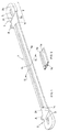
- the tie rod (1) has a monolithic structure obtained with moulded plastic materials, showing a long central section (1a) with longitudinal stiffening ribs (1b) on both sides and joined with two perfectly symmetrical large ears (2) on opposite sides, having a vaguely drop-like shape.
- longitudinal stiffening ribs (1b) extend slightly beyond the connections located between the central section (1a) and the lateral ears (2).
- Each ear (2) has a different thickness, since the most internal part (2a) has the same thickness as the central rectilinear section (1a) of the tie rod (1), and the most external part (2b), with basically semi-elliptical profile and traditional eye (3), has a double thickness; it being provided that the two parts with different thickness are joined by rectilinear steps (2c) with transversal direction on both sides of the tie rod (1).
- the most internal and thinnest part (2a) located on each side of the two ears (2) is bordered by two projecting parts with higher thickness on opposite sides; inwards, this part is bordered by the end (1c) of the rectilinear rib (1b) of the central section (1a) and outwards by the transversal step (2c).
- the distance between the two projecting parts (1c, 2c) is not casual; it is slightly higher than the thickness of the traditional wooden boards that are typically used for the realisation of formworks for reinforced concrete.
- the board can be correctly matched with the tie rod (1) only in one of the housings (2a); once correctly inserted between the two projecting parts (1c, 2c) that delimit the housing (2a), the board cannot slide forward or backwards, being held in place by the projecting parts.
- each ear (2) will protrude from the consolidated cement manufacture.
- the ear (2) is cut flush with the external side of the cement manufacture; practically, in the tie rod (1) according to the present invention, the transversal cutting line is located slightly beyond the end (1c) of each rib (1b) of the central section (1a), that is on the ideal internal transversal edge of the thinner section (2a) of each ear (2) that acted as centring housing for the edge of the board during the construction of the formwork.
- the presence of the new plastic tie rod (1) inside the consolidated cement manufacture guarantees that the external walls of the cement manufacture are free from the rust stains that are typical when using traditional metal tie rods.
- letter (A) is used to indicate two short pierced appendixes that can be used to fix the tie rod to the top of the formwork with nails, on the upper edges of the last boards of two opposite walls.
- Fig. 3 shows a simplified version of the tie rod according to the present invention, that differs from the first version only in that the tie rod (10) obtained by moulding a single piece of plastic material terminates on both sides with two enlarged ears (20) with constant thickness equal to the thickness of the central section (10a) with longitudinal stiffening ribs (10b) interrupted near the ear (20) with central eye (30).
Landscapes
- Engineering & Computer Science (AREA)
- Architecture (AREA)
- Mechanical Engineering (AREA)
- Civil Engineering (AREA)
- Structural Engineering (AREA)
- Forms Removed On Construction Sites Or Auxiliary Members Thereof (AREA)
Applications Claiming Priority (2)
| Application Number | Priority Date | Filing Date | Title |
|---|---|---|---|
| IT2001AN000002U ITAN20010002U1 (it) | 2001-01-12 | 2001-01-12 | Tirante per la realizzazione di casseforme per cemento armato |
| ITAN010002U | 2001-01-12 |
Publications (2)
| Publication Number | Publication Date |
|---|---|
| EP1234930A2 true EP1234930A2 (de) | 2002-08-28 |
| EP1234930A3 EP1234930A3 (de) | 2003-11-19 |
Family
ID=11437272
Family Applications (1)
| Application Number | Title | Priority Date | Filing Date |
|---|---|---|---|
| EP01830800A Withdrawn EP1234930A3 (de) | 2001-01-12 | 2001-12-21 | Abstandhalter für die Herstellung von Schalungen für Stahlbeton |
Country Status (2)
| Country | Link |
|---|---|
| EP (1) | EP1234930A3 (de) |
| IT (1) | ITAN20010002U1 (de) |
Cited By (1)
| Publication number | Priority date | Publication date | Assignee | Title |
|---|---|---|---|---|
| CN102031869A (zh) * | 2011-01-28 | 2011-04-27 | 中国建筑第八工程局有限公司 | 水平模板钢结构托架 |
Family Cites Families (5)
| Publication number | Priority date | Publication date | Assignee | Title |
|---|---|---|---|---|
| US3142883A (en) * | 1962-06-22 | 1964-08-04 | Symons Mfg Co | Tie rod and anchor bolt combination with external anchor point |
| DE1684496A1 (de) * | 1967-08-08 | 1971-03-18 | Franz Tempes | Abstandhalter fuer Mantelwaende von Mantelbeton |
| DE2830028A1 (de) * | 1978-07-07 | 1980-01-17 | Karl Liedgens | Schalungszuganker |
| US4730422A (en) * | 1985-11-20 | 1988-03-15 | Young Rubber Company | Insulating non-removable type concrete wall forming structure and device and system for attaching wall coverings thereto |
| US6138981A (en) * | 1998-08-03 | 2000-10-31 | H.K. Composites, Inc. | Insulating connectors used to retain forms during the manufacture of composite wall structures |
-
2001
- 2001-01-12 IT IT2001AN000002U patent/ITAN20010002U1/it unknown
- 2001-12-21 EP EP01830800A patent/EP1234930A3/de not_active Withdrawn
Cited By (1)
| Publication number | Priority date | Publication date | Assignee | Title |
|---|---|---|---|---|
| CN102031869A (zh) * | 2011-01-28 | 2011-04-27 | 中国建筑第八工程局有限公司 | 水平模板钢结构托架 |
Also Published As
| Publication number | Publication date |
|---|---|
| EP1234930A3 (de) | 2003-11-19 |
| ITAN20010002U1 (it) | 2002-07-12 |
| ITAN20010002V0 (it) | 2001-01-12 |
Similar Documents
| Publication | Publication Date | Title |
|---|---|---|
| US3778019A (en) | Form structure | |
| CN203755665U (zh) | 清水混凝土梁模板托架和清水混凝土梁模板系统 | |
| EP1234930A2 (de) | Abstandhalter für die Herstellung von Schalungen für Stahlbeton | |
| KR101791043B1 (ko) | 천정보 슬리브 거푸집 고정바 | |
| CN104763138B (zh) | 一种抗注塑缩影的建筑模板 | |
| EP1282754A1 (de) | Schalungssystem für betonbalken | |
| CN111479970A (zh) | 模板壁面板和模板组件 | |
| JP2945905B1 (ja) | 型枠構造および型枠固定金物 | |
| CN108979146A (zh) | 建筑模板的对接连接件以及建筑模板的对接连接方法 | |
| US4444374A (en) | Prefabricated concrete forms assembly | |
| CN104763137B (zh) | 一种阴阳角塑料模板 | |
| US7146767B2 (en) | Standardized arched jamb assembly and method | |
| US1922994A (en) | Trimming joint | |
| CN201962939U (zh) | 一种精密建筑模板 | |
| JP3051342B2 (ja) | スリーブ | |
| CN217151222U (zh) | 一种可调式洞口反坎模具 | |
| KR101791041B1 (ko) | 천정보 슬리브 거푸집 고정바 | |
| KR200300444Y1 (ko) | 창호공사용 수평맞춤부재 | |
| JP3280357B2 (ja) | 庇の施工方法 | |
| CN218639933U (zh) | 防止水泥砂浆溢出的浇筑模具框 | |
| CN108951953B (zh) | 用于预制墙体竖向连接的可滑移式模具 | |
| CN212561940U (zh) | 一种石膏板拼接工具 | |
| CN221920248U (zh) | 模板组合结构和结合组件 | |
| CN212027516U (zh) | 一种新型框料型材结构 | |
| CN218965664U (zh) | 一种利用弯料的木料拼件 |
Legal Events
| Date | Code | Title | Description |
|---|---|---|---|
| PUAI | Public reference made under article 153(3) epc to a published international application that has entered the european phase |
Free format text: ORIGINAL CODE: 0009012 |
|
| AK | Designated contracting states |
Kind code of ref document: A2 Designated state(s): AT BE CH CY DE DK ES FI FR GB GR IE IT LI LU MC NL PT SE TR |
|
| AX | Request for extension of the european patent |
Free format text: AL;LT;LV;MK;RO;SI |
|
| PUAL | Search report despatched |
Free format text: ORIGINAL CODE: 0009013 |
|
| AK | Designated contracting states |
Kind code of ref document: A3 Designated state(s): AT BE CH CY DE DK ES FI FR GB GR IE IT LI LU MC NL PT SE TR |
|
| AX | Request for extension of the european patent |
Extension state: AL LT LV MK RO SI |
|
| 17P | Request for examination filed |
Effective date: 20040512 |
|
| AKX | Designation fees paid |
Designated state(s): AT BE CH CY DE DK ES FI FR GB GR IE IT LI LU MC NL PT SE TR |
|
| GRAP | Despatch of communication of intention to grant a patent |
Free format text: ORIGINAL CODE: EPIDOSNIGR1 |
|
| STAA | Information on the status of an ep patent application or granted ep patent |
Free format text: STATUS: THE APPLICATION IS DEEMED TO BE WITHDRAWN |
|
| 18D | Application deemed to be withdrawn |
Effective date: 20070606 |