EP1234985A2 - Système de liaison par serrage - Google Patents
Système de liaison par serrage Download PDFInfo
- Publication number
- EP1234985A2 EP1234985A2 EP02003877A EP02003877A EP1234985A2 EP 1234985 A2 EP1234985 A2 EP 1234985A2 EP 02003877 A EP02003877 A EP 02003877A EP 02003877 A EP02003877 A EP 02003877A EP 1234985 A2 EP1234985 A2 EP 1234985A2
- Authority
- EP
- European Patent Office
- Prior art keywords
- clamping part
- connector system
- clamp connector
- adapter element
- housing
- Prior art date
- Legal status (The legal status is an assumption and is not a legal conclusion. Google has not performed a legal analysis and makes no representation as to the accuracy of the status listed.)
- Granted
Links
- 230000000149 penetrating effect Effects 0.000 claims description 2
- 238000011065 in-situ storage Methods 0.000 abstract 1
- 229910052751 metal Inorganic materials 0.000 description 4
- 239000002184 metal Substances 0.000 description 4
- 238000003892 spreading Methods 0.000 description 4
- 238000010276 construction Methods 0.000 description 3
- 238000005516 engineering process Methods 0.000 description 2
- 238000003780 insertion Methods 0.000 description 2
- 230000037431 insertion Effects 0.000 description 2
- 230000004308 accommodation Effects 0.000 description 1
- 229910052782 aluminium Inorganic materials 0.000 description 1
- XAGFODPZIPBFFR-UHFFFAOYSA-N aluminium Chemical compound [Al] XAGFODPZIPBFFR-UHFFFAOYSA-N 0.000 description 1
- 238000004873 anchoring Methods 0.000 description 1
- 230000015572 biosynthetic process Effects 0.000 description 1
- 230000000694 effects Effects 0.000 description 1
- 238000005755 formation reaction Methods 0.000 description 1
- 238000007373 indentation Methods 0.000 description 1
- 238000001746 injection moulding Methods 0.000 description 1
- 238000005304 joining Methods 0.000 description 1
- 238000004519 manufacturing process Methods 0.000 description 1
- 239000000463 material Substances 0.000 description 1
- 238000003825 pressing Methods 0.000 description 1
Images


Classifications
-
- F—MECHANICAL ENGINEERING; LIGHTING; HEATING; WEAPONS; BLASTING
- F16—ENGINEERING ELEMENTS AND UNITS; GENERAL MEASURES FOR PRODUCING AND MAINTAINING EFFECTIVE FUNCTIONING OF MACHINES OR INSTALLATIONS; THERMAL INSULATION IN GENERAL
- F16B—DEVICES FOR FASTENING OR SECURING CONSTRUCTIONAL ELEMENTS OR MACHINE PARTS TOGETHER, e.g. NAILS, BOLTS, CIRCLIPS, CLAMPS, CLIPS OR WEDGES; JOINTS OR JOINTING
- F16B7/00—Connections of rods or tubes, e.g. of non-circular section, mutually, including resilient connections
- F16B7/04—Clamping or clipping connections
- F16B7/044—Clamping or clipping connections for rods or tubes being in angled relationship
- F16B7/0446—Clamping or clipping connections for rods or tubes being in angled relationship for tubes using the innerside thereof
- F16B7/0473—Clamping or clipping connections for rods or tubes being in angled relationship for tubes using the innerside thereof with hook-like parts gripping, e.g. by expanding, behind the flanges of a profile
Definitions
- the invention relates to a clamp connector system for releasably connecting two Elements, at least one of which is an undercut longitudinal groove and the another has a receiving space formed therein, with one in the Anchoring elements that can be inserted into the longitudinal groove and inserted into the receiving space having clamping part, the anchor elements by actuating a Actuating element can be clamped against the undercut of the longitudinal groove.
- Clamp connector systems of this type are used, for example, in Construction of shelving systems, exhibition stands and the like.
- individual elements with the help of the clamp connector systems in one Quick connection technology put together, so that a quick assembly and disassembly of the shelving system, the exhibition structures or the like is possible.
- This is a quick and easy handling of the clamp connector system is an advantage.
- Clamp connector systems that meet these requirements are in large numbers known.
- DE 42 39 199 A1 shows a clamp connection, by means of which two profile pieces, at least one of which is an undercut Longitudinal groove and the other has a rectangular hollow profile, with each other can be connected.
- profile pieces shown in this publication it is obviously metal or plastic profiles, where for example in the area of trade fair construction, usually extruded metal, for example aluminum profiles.
- a bearing member having a housing in which a Formations for engaging in an undercut longitudinal groove of a Adjacent profile having retaining member used in the form of a leaf spring is and can be operated via an eccentric.
- connection systems through a secure connection of two profile pieces as well by simple handling, however, they are in use limited.
- the known connection systems are for example for the Connect a wooden element with an undercut longitudinal groove having element is only suitable to a limited extent. It is also a perfect fit both the actual connecting element and the hollow profile, in which the connecting element is used, required.
- the invention has for its object to provide a clamp connector system of the type mentioned, which offers more flexible uses and which is particularly useful in connection with wooden elements.
- the invention proposes a clamp connector system for the detachable connection of two elements, at least one of which has an undercut longitudinal groove and the other has a receiving space formed therein, with a clamping part which can be inserted into the receiving space and has clamping elements which can be clamped in the longitudinal groove , the anchor elements of which can be clamped against the undercut of the longitudinal groove by actuating an actuating element, the clamping connector system having an adapter element for receiving the clamping part, the adapter element with the clamping part accommodated therein being insertable into the receiving space.
- an adapter element provided according to the invention enables one Coordination to differently dimensioned recording rooms, in which the Clamping part is to be used. For example, one and the same clamping part by using different adapter elements on differently shaped Recording rooms are adapted.
- the invention extends Adapter element the possible range of applications of the clamp connector system. So the clamp connector system according to the invention can, as is known, in Metal or plastic profiles are used, but it can also be used in In connection with wooden elements. Can with advantage For example, structures can be provided on the adapter element by means of which this and together with this the clamping part is fixed in the receiving space can be.
- the adapter element is included connectable to the clamping part. This allows the clamping part with the adapter element connected and then inserted into the recording room as a unit. To enable an exchange of the adapter element, it is from Advantage if the adapter element with the clamping part, as with another advantageous embodiment of the invention is proposed, releasably connectable.
- the adapter element and the clamping part can be according to another advantageous further development of the invention can be positively connected, for which purpose corresponding connection structures are formed for each of these elements are.
- the Clamping part on a housing, and the locking cams are through over the housing protruding portions of a transverse to the housing and the Housing on two sides penetrating guide and expansion pin for a Leaf spring element having anchor elements arranged in the housing educated.
- one element namely the leadership and Spreader pin, perform two functions.
- it serves to manage one Leaf spring element and the spreading of two sections of the Leaf spring element, on the other hand form its over the housing of the clamping part protruding sections for releasably connecting the clamping part with the Adapter element provided locking cams. This makes it easier and therefore Realized inexpensive construction of the clamping part.
- this is Adapter element essentially U-shaped with two on the side Clamping part adjacent legs and a web connecting the legs, the anchor elements when connected to the adapter element on a free end face of the clamping part opposite the web are arranged.
- the clamping part is of such a design Surround the adapter element on three sides, so that with the adapter element Clamping part in two dimensions to the dimensions of a recording room can be adjusted.
- the actuating element is advantageously located for jamming the anchor elements on a side not covered by the adapter element of the clamping part. This ensures that the actuator at all times is freely accessible.
- the actuator when this under a spring force protrudes above the contour of the clamping part, for fixing the Clamping part can be used in the receiving space by the actuating element into a corresponding one, formed in a wall of the receiving space Opening protrudes.
- Adapter element guided through opening for carrying out a Fastener may be provided.
- a U-shaped clamping part provided two through openings be, one through each of the legs, substantially in its Is guided in the longitudinal direction.
- Fastening elements such as screws or the like, are performed.
- the through hole in one of their End areas with a screw head, for example Extension.
- the clamp connector system in a housing of Clamping part arranged leaf spring element which has an opening has, through which the actuating element is passed.
- This opening advantageously has one of the regular contours along its circumferential contour different paragraph. This paragraph works with one on the Actuator trained heel edge together and thus prevents Tilting the actuator when this in the direction of Housing is pressed.
- clamping part is only a possible embodiment, such as it for realizing the clamp connector system according to the invention not required, but it can be any other suitable clamping part be used.
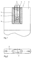
- Fig. 1 is a partially sectioned view of the invention Clamp connector system 1 shown, which is in an element to be connected 2 is arranged in a receiving space 3.
- the invention Clamp connector system 1 has one inserted in an adapter element 5 Clamping part 4, the unit consisting of clamping part 4 and adapter element 5 overall in the receiving space 3 (Fig. 2) of the element 2 is sunk.
- the Clamping part 4 has an actuatable element 8
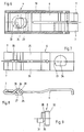
- clamping part 4 The exact structure of the clamping part 4 will be explained later with reference to FIGS. 5 and 6 explained in more detail.
- Fig. 2 is an end view of a plate-shaped element 2 with the therein trained receiving space 3 shown.
- the receiving space 3 is one-sided Open recess formed in which the clamp connector system 1 as Combination of adapter element 5 and clamping part 4 can be sunk.
- the adapter element 5 has one essentially U-shaped shape and is composed of two elongated legs 9 and 10, which via a connecting web 11 are joined together in addition to the U-shape mentioned.
- the adapter element 5 Through the Legs 9 and 10 are each guided in the longitudinal direction, axial Through openings 13 and 14 introduced at the free end of the legs each have extensions 15 and 16. These through openings serve for passing a fastener, in particular screws, the extensions 15 and 16 to accommodate the respective Serve screw head, so as to complete the To allow screw head with the free end of the legs 9 or 10.
- the leg has recesses 17 and 18. These recesses serve to accommodate locking cams arranged on the clamping part 4 for Forming a positive connection between the adapter element 5 and the clamping part 4.
- the Recesses 17 and 18 up to a flat side of the adapter element 5 extend.
- this is for the positive connection between the Adapter element 5 and the clamping part 4 or for mounting the clamping part 4 in the adapter element 5 is not required, but only in terms of production technology conditionally.
- the Clamping part 4 has a housing 19 within which the Leaf spring element 6 is located. Through an opening in the housing and a Opening 23 in the leaf spring element 6 extends through it Actuating element 8 into a recess formed in the housing base 22 in.
- the opening 23 in the leaf spring element 6 is circular, however, has a shape deviating from the circular contour on one side.
- a shoulder 34 is formed along a secant, the function of which follows is explained in more detail.
- the actuator 8 can be sunk into the housing 19 by pressing against the spring force are so that the clamping part 4 with the adapter element 5 arranged thereon introduced a recording room and by means of the spring-loaded Actuator, which with its projecting beyond the housing 19 Section in a corresponding opening formed in the receiving space snaps into place, can be connected.
- This is supported by such an impression Actuating element with a shoulder 35 formed thereon (see FIG. 9) from the shoulder 34 formed in the opening 23 of the leaf spring element 6.
- This causes on the one hand that the leaf spring element 6 follows the indentation and not so formed by one on the actuating element 8 Functional structure (eccentric 30, see Fig. 9) solves.
- a tilting of the Actuator 8 prevented.
- FIG. 6 there is a circular recess 22 trained stop 24 to recognize the movement of the Actuator 8 limited.
- Figs. 7 and 8 the leaf spring element 6 is shown in more detail. outgoing from the side of the leaf spring element on which the anchor elements 7 are formed are, a longitudinal slot 33 extends into the leaf spring element 6, which the leaf spring element 6 divided on this side into two spring arms 25 and 26. In the side of the leaf spring element 6 opposite the anchor elements 7 there is an opening 23 which is used to actuate the leaf spring element interacts with the actuating element 8.
- the two spring arms 25 and 26 form a passage 29 by reversing the bends. in the The assembly state is, as shown in Fig. 5, through this passage of the guide and Spreading pin 21 out.
- the two spring arms 25 and 26 each on bevels 27 and 28, which with the guide and Spreader pin 21 in the direction of the anchor elements 7 opposite end of the leaf spring element 6 directed pulling movement of the leaf spring element 6 with the guide and fixed in the housing Spreader pin 21 cooperate such that the anchor elements 7 next to the Pull movement continue to spread.
- This combined train and Spreading movement finally causes the jamming of the anchor elements 7 in an undercut longitudinal groove of an adjacent element with which the Element in which the clamp connector system 1 is integrated, are connected should.
- the guide and expansion pin 21 is dimensioned so that it through openings in the housing 19 protrudes laterally and with its protruding sections cam-like in the recesses formed on the adapter element 5 17 and 18 engages (see Fig. 1, where the guide and expansion pin 21 is not shown).
- actuating element 8 is shown.
- the Actuating element 8 has and a head 32 and a counterpart 31 between head 32 and counterpart 31 eccentrically arranged eccentric 30.
- Das Counterpart 31 also acts with that formed in the recess 22 Stop 24 together to the movement of the actuator 8 restrict.
- the Counterpart 31 corresponds to paragraph 34 in opening 23 Flattening 36 on.
- the actuating element 8 can only have an angular position are used, but is then secured by twisting. On one (not shown) formed in the head 32 approach structure appropriate tool with which the Actuator 8 can be rotated.
- FIGS. 11 and 12 show an alternative exemplary embodiment for a Adapter element 5 of the invention shown.
- the one shown in these figures Adapter element 5 is essentially the same as the adapter element from FIG. 3 also consists of two parallel to each other with a distance Legs 9 and 10 together, which are connected to one another via a connecting web 11 are connected.
- the legs 9 and 10 are each analogous to that Embodiment according to Figure 3 extending in the longitudinal direction of the legs Through openings 13 and 14 introduced, which in the Connecting web 11 opposite end area with extensions 15 or 16 are provided.
- the adapter element 5 shown in FIGS. 11 and 12 has to connect to a clamping part 4 on its two legs 9 or 10 two at the same height, each on the opposite Leg directed locking projections 37, 38. Replace these locking tabs the provided in the adapter element 5 shown in Figure 3 Notches 17 and 18.
- the adapter element 5 shown in Figures 11 and 12 is for the Use provided with a (not shown here) clamping part 4, which has latching openings in its housing, which are so in terms of their position are arranged so that the applied to the adapter element 5 Engage locking projections in such locking openings if the clamping part is correctly in the adapter element is inserted.
- 11 and 12 are also shown in FIGS projecting extensions 39 arranged at the free ends of the legs 9 and 10 and to recognize 40, which took to spread the legs 9 and 10 in order to be able to detach one in the adapter element 5 to facilitate recorded clamping part.
- the adapter element 5 is made in the above exemplary embodiments Plastic, preferably by injection molding.
- clamp connector system is compared with Clamp connector systems from the prior art a higher flexibility achieved by a clamping part of a predetermined size by means of an intermediary an adapter element on the one hand to differently dimensioned Recording rooms can be adapted, on the other hand in other elements as profile elements made of plastic or metal and here can be used in particular in wooden elements. This is achieved through the through openings in the adapter element, into which Fasteners, such as screws to fix the Adapter element and thus the clamping part can be performed.
Landscapes
- Engineering & Computer Science (AREA)
- General Engineering & Computer Science (AREA)
- Mechanical Engineering (AREA)
- Joining Of Building Structures In Genera (AREA)
- Details Of Connecting Devices For Male And Female Coupling (AREA)
- Mutual Connection Of Rods And Tubes (AREA)
- Signal Processing For Digital Recording And Reproducing (AREA)
- Snaps, Bayonet Connections, Set Pins, And Snap Rings (AREA)
- Coupling Device And Connection With Printed Circuit (AREA)
- Cable Accessories (AREA)
- Saccharide Compounds (AREA)
- Paper (AREA)
- Automobile Manufacture Line, Endless Track Vehicle, Trailer (AREA)
- Clamps And Clips (AREA)
Applications Claiming Priority (2)
| Application Number | Priority Date | Filing Date | Title |
|---|---|---|---|
| DE20103064U DE20103064U1 (de) | 2001-02-21 | 2001-02-21 | Klemmverbindersystem |
| DE20103064U | 2001-02-21 |
Publications (3)
| Publication Number | Publication Date |
|---|---|
| EP1234985A2 true EP1234985A2 (fr) | 2002-08-28 |
| EP1234985A3 EP1234985A3 (fr) | 2002-12-11 |
| EP1234985B1 EP1234985B1 (fr) | 2006-04-12 |
Family
ID=7953313
Family Applications (1)
| Application Number | Title | Priority Date | Filing Date |
|---|---|---|---|
| EP02003877A Expired - Lifetime EP1234985B1 (fr) | 2001-02-21 | 2002-02-21 | Système de liaison par serrage |
Country Status (6)
| Country | Link |
|---|---|
| EP (1) | EP1234985B1 (fr) |
| AT (1) | ATE323231T1 (fr) |
| DE (2) | DE20103064U1 (fr) |
| DK (1) | DK1234985T3 (fr) |
| ES (1) | ES2261533T3 (fr) |
| PT (1) | PT1234985E (fr) |
Cited By (2)
| Publication number | Priority date | Publication date | Assignee | Title |
|---|---|---|---|---|
| US7357592B2 (en) | 2005-10-13 | 2008-04-15 | Hestex Systems B.V | Clamping joint system |
| EP2910699A1 (fr) | 2010-05-07 | 2015-08-26 | Hestex Systems B.V. | Système d'élément de profilé d'arête |
Families Citing this family (8)
| Publication number | Priority date | Publication date | Assignee | Title |
|---|---|---|---|---|
| EP2006550A1 (fr) | 2007-06-23 | 2008-12-24 | Hestex Systems B.V. | Dispositif de connexion |
| EP2088332A1 (fr) | 2008-02-08 | 2009-08-12 | Hestex Systems B.V. | Dispositif de connexion |
| DE202009003881U1 (de) | 2009-03-19 | 2009-05-28 | Hestex Systems B.V. | Plakatrahmeneinrichtung |
| DE202010011126U1 (de) | 2010-08-06 | 2010-12-02 | Hestex Systems B.V. | Lager und Transportvorrichtung |
| DE202012101930U1 (de) | 2012-05-25 | 2012-07-04 | Hestex Systems B.V. | Bausystem, insbesondere Messebausystem |
| ES2638849T3 (es) | 2015-01-21 | 2017-10-24 | Hestex Systems B.V. | Conector de apriete |
| DE202017102580U1 (de) | 2017-05-02 | 2017-07-07 | Hestex Systems B.V. | Rahmenelement |
| DE102023114450A1 (de) * | 2023-06-01 | 2024-12-05 | Michael Mahle | Verbindungsanordnung und Holzkonstruktion |
Citations (2)
| Publication number | Priority date | Publication date | Assignee | Title |
|---|---|---|---|---|
| DE4239199A1 (de) | 1992-11-21 | 1994-05-26 | Hestex Systems Bv | Klemmverbindung |
| DE19817427A1 (de) | 1998-04-18 | 1999-10-21 | Offenbroich A | Klemmverbinder |
Family Cites Families (1)
| Publication number | Priority date | Publication date | Assignee | Title |
|---|---|---|---|---|
| CN1117219C (zh) * | 1997-08-12 | 2003-08-06 | 西马洲际股份有限公司 | 可拆式连接两个成型件的装置 |
-
2001
- 2001-02-21 DE DE20103064U patent/DE20103064U1/de not_active Expired - Lifetime
-
2002
- 2002-02-21 AT AT02003877T patent/ATE323231T1/de active
- 2002-02-21 PT PT02003877T patent/PT1234985E/pt unknown
- 2002-02-21 ES ES02003877T patent/ES2261533T3/es not_active Expired - Lifetime
- 2002-02-21 DE DE50206350T patent/DE50206350D1/de not_active Expired - Lifetime
- 2002-02-21 EP EP02003877A patent/EP1234985B1/fr not_active Expired - Lifetime
- 2002-02-21 DK DK02003877T patent/DK1234985T3/da active
Patent Citations (2)
| Publication number | Priority date | Publication date | Assignee | Title |
|---|---|---|---|---|
| DE4239199A1 (de) | 1992-11-21 | 1994-05-26 | Hestex Systems Bv | Klemmverbindung |
| DE19817427A1 (de) | 1998-04-18 | 1999-10-21 | Offenbroich A | Klemmverbinder |
Cited By (2)
| Publication number | Priority date | Publication date | Assignee | Title |
|---|---|---|---|---|
| US7357592B2 (en) | 2005-10-13 | 2008-04-15 | Hestex Systems B.V | Clamping joint system |
| EP2910699A1 (fr) | 2010-05-07 | 2015-08-26 | Hestex Systems B.V. | Système d'élément de profilé d'arête |
Also Published As
| Publication number | Publication date |
|---|---|
| DE20103064U1 (de) | 2001-06-28 |
| PT1234985E (pt) | 2006-08-31 |
| EP1234985B1 (fr) | 2006-04-12 |
| DK1234985T3 (da) | 2006-08-14 |
| EP1234985A3 (fr) | 2002-12-11 |
| ES2261533T3 (es) | 2006-11-16 |
| DE50206350D1 (de) | 2006-05-24 |
| ATE323231T1 (de) | 2006-04-15 |
Similar Documents
| Publication | Publication Date | Title |
|---|---|---|
| DE4330102A1 (de) | Verbindungselement | |
| CH667139A5 (de) | Verbindungsbeschlag. | |
| EP1441094A1 (fr) | Ferrure pour une fênetre | |
| DE102009012438A1 (de) | Pfostenverbinder | |
| EP3535824B1 (fr) | Support de jeu de barres et ensemble correspondant | |
| EP1141562A1 (fr) | Dispositif d'assemblage permettant de reunir une premiere piece a une seconde | |
| EP1234985B1 (fr) | Système de liaison par serrage | |
| EP2852768A1 (fr) | Dispositif de fixation | |
| DE102008034830A1 (de) | Bausatz zum Verbinden von Profilstäben | |
| DE20009316U1 (de) | Befestigungsplatte zur Befestigung eines Scharnierarmes eines Möbelscharniers | |
| DE102017125877A1 (de) | Verankerungsbeschlag zur Verankerung in einem Werkstück | |
| AT7578U1 (de) | Verbindung von zwei profilstäben und absperrungskonstruktion mit derartigen verbindungen | |
| EP1229282B1 (fr) | Adaptateur pour le montage de collier de fixation | |
| AT403500B (de) | Beschlagteileverbindung | |
| DE102007018370B3 (de) | Gebäudeelement mit einem im Rahmen dichtend gehaltenen Ausfachungselement | |
| EP0267200A1 (fr) | Dispositif pour l'assemblage demontable de deux elements de construction. | |
| DE102007009667B4 (de) | Profilkonstruktion | |
| DE1966962C3 (de) | Beschlag zum lösbaren Verbinden zweier senkrecht aufeinanderstoßender plattenförmiger Bauteile, insbesondere Möbelteile | |
| DE29920508U1 (de) | Treibstangenschloss | |
| DE10220284C1 (de) | Vorrichtung zur Halterung von Funktionsteilen | |
| DE10001662A1 (de) | Schutzbeschlag | |
| DE102010055856B4 (de) | Schnellkupplung für die Befestigung von Zubehör an einem Fahrrad | |
| EP4575119A1 (fr) | Raccord en t et procédé d'assemblage d'un raccord en t | |
| EP3228217A2 (fr) | Élément structurel | |
| DE10144982C2 (de) | Befestigungselement |
Legal Events
| Date | Code | Title | Description |
|---|---|---|---|
| PUAI | Public reference made under article 153(3) epc to a published international application that has entered the european phase |
Free format text: ORIGINAL CODE: 0009012 |
|
| AK | Designated contracting states |
Kind code of ref document: A2 Designated state(s): AT BE CH CY DE DK ES FI FR GB GR IE IT LI LU MC NL PT SE TR |
|
| AX | Request for extension of the european patent |
Free format text: AL;LT;LV;MK;RO;SI |
|
| PUAL | Search report despatched |
Free format text: ORIGINAL CODE: 0009013 |
|
| AK | Designated contracting states |
Kind code of ref document: A3 Designated state(s): AT BE CH CY DE DK ES FI FR GB GR IE IT LI LU MC NL PT SE TR |
|
| AX | Request for extension of the european patent |
Free format text: AL;LT;LV;MK;RO;SI |
|
| 17P | Request for examination filed |
Effective date: 20030611 |
|
| AKX | Designation fees paid |
Designated state(s): AT BE CH CY DE DK ES FI FR GB GR IE IT LI LU MC NL PT SE TR |
|
| 17Q | First examination report despatched |
Effective date: 20050511 |
|
| GRAP | Despatch of communication of intention to grant a patent |
Free format text: ORIGINAL CODE: EPIDOSNIGR1 |
|
| GRAS | Grant fee paid |
Free format text: ORIGINAL CODE: EPIDOSNIGR3 |
|
| GRAA | (expected) grant |
Free format text: ORIGINAL CODE: 0009210 |
|
| AK | Designated contracting states |
Kind code of ref document: B1 Designated state(s): AT BE CH CY DE DK ES FI FR GB GR IE IT LI LU MC NL PT SE TR |
|
| PG25 | Lapsed in a contracting state [announced via postgrant information from national office to epo] |
Ref country code: IT Free format text: LAPSE BECAUSE OF FAILURE TO SUBMIT A TRANSLATION OF THE DESCRIPTION OR TO PAY THE FEE WITHIN THE PRESCRIBED TIME-LIMIT;WARNING: LAPSES OF ITALIAN PATENTS WITH EFFECTIVE DATE BEFORE 2007 MAY HAVE OCCURRED AT ANY TIME BEFORE 2007. THE CORRECT EFFECTIVE DATE MAY BE DIFFERENT FROM THE ONE RECORDED. Effective date: 20060412 Ref country code: FI Free format text: LAPSE BECAUSE OF FAILURE TO SUBMIT A TRANSLATION OF THE DESCRIPTION OR TO PAY THE FEE WITHIN THE PRESCRIBED TIME-LIMIT Effective date: 20060412 |
|
| REG | Reference to a national code |
Ref country code: GB Ref legal event code: FG4D Free format text: NOT ENGLISH |
|
| REG | Reference to a national code |
Ref country code: CH Ref legal event code: EP |
|
| REF | Corresponds to: |
Ref document number: 50206350 Country of ref document: DE Date of ref document: 20060524 Kind code of ref document: P |
|
| REG | Reference to a national code |
Ref country code: IE Ref legal event code: FG4D Free format text: LANGUAGE OF EP DOCUMENT: GERMAN |
|
| REG | Reference to a national code |
Ref country code: CH Ref legal event code: NV Representative=s name: E. BLUM & CO. PATENTANWAELTE |
|
| REG | Reference to a national code |
Ref country code: SE Ref legal event code: TRGR |
|
| GBT | Gb: translation of ep patent filed (gb section 77(6)(a)/1977) |
Effective date: 20060705 |
|
| REG | Reference to a national code |
Ref country code: DK Ref legal event code: T3 |
|
| REG | Reference to a national code |
Ref country code: PT Ref legal event code: SC4A Effective date: 20060707 |
|
| REG | Reference to a national code |
Ref country code: GR Ref legal event code: EP Ref document number: 20060402353 Country of ref document: GR |
|
| ET | Fr: translation filed | ||
| REG | Reference to a national code |
Ref country code: ES Ref legal event code: FG2A Ref document number: 2261533 Country of ref document: ES Kind code of ref document: T3 |
|
| PLBE | No opposition filed within time limit |
Free format text: ORIGINAL CODE: 0009261 |
|
| STAA | Information on the status of an ep patent application or granted ep patent |
Free format text: STATUS: NO OPPOSITION FILED WITHIN TIME LIMIT |
|
| PG25 | Lapsed in a contracting state [announced via postgrant information from national office to epo] |
Ref country code: MC Free format text: LAPSE BECAUSE OF NON-PAYMENT OF DUE FEES Effective date: 20070228 |
|
| 26N | No opposition filed |
Effective date: 20070115 |
|
| REG | Reference to a national code |
Ref country code: CH Ref legal event code: PFA Owner name: HESTEX SYSTEMS B.V. Free format text: HESTEX SYSTEMS B.V.#ZWAANSPRENGWEG 19#7332 BE APELDOORN (NL) -TRANSFER TO- HESTEX SYSTEMS B.V.#ZWAANSPRENGWEG 19#7332 BE APELDOORN (NL) |
|
| PG25 | Lapsed in a contracting state [announced via postgrant information from national office to epo] |
Ref country code: LU Free format text: LAPSE BECAUSE OF NON-PAYMENT OF DUE FEES Effective date: 20070221 Ref country code: CY Free format text: LAPSE BECAUSE OF FAILURE TO SUBMIT A TRANSLATION OF THE DESCRIPTION OR TO PAY THE FEE WITHIN THE PRESCRIBED TIME-LIMIT Effective date: 20060412 |
|
| REG | Reference to a national code |
Ref country code: FR Ref legal event code: PLFP Year of fee payment: 15 |
|
| REG | Reference to a national code |
Ref country code: FR Ref legal event code: PLFP Year of fee payment: 16 |
|
| PGFP | Annual fee paid to national office [announced via postgrant information from national office to epo] |
Ref country code: SE Payment date: 20170216 Year of fee payment: 16 Ref country code: GR Payment date: 20170217 Year of fee payment: 16 |
|
| PGFP | Annual fee paid to national office [announced via postgrant information from national office to epo] |
Ref country code: AT Payment date: 20170217 Year of fee payment: 16 Ref country code: PT Payment date: 20170216 Year of fee payment: 16 Ref country code: DK Payment date: 20170216 Year of fee payment: 16 Ref country code: IE Payment date: 20170220 Year of fee payment: 16 |
|
| PGFP | Annual fee paid to national office [announced via postgrant information from national office to epo] |
Ref country code: TR Payment date: 20170213 Year of fee payment: 16 |
|
| REG | Reference to a national code |
Ref country code: DE Ref legal event code: R082 Ref document number: 50206350 Country of ref document: DE Representative=s name: BRINKMANN & PARTNER PATENTANWAELTE PARTNERSCHA, DE Ref country code: DE Ref legal event code: R082 Ref document number: 50206350 Country of ref document: DE Representative=s name: RAUSCH WANISCHECK-BERGMANN BRINKMANN PARTNERSC, DE |
|
| REG | Reference to a national code |
Ref country code: FR Ref legal event code: PLFP Year of fee payment: 17 |
|
| PGFP | Annual fee paid to national office [announced via postgrant information from national office to epo] |
Ref country code: CH Payment date: 20180316 Year of fee payment: 18 |
|
| PGFP | Annual fee paid to national office [announced via postgrant information from national office to epo] |
Ref country code: BE Payment date: 20180329 Year of fee payment: 17 |
|
| PGFP | Annual fee paid to national office [announced via postgrant information from national office to epo] |
Ref country code: ES Payment date: 20180427 Year of fee payment: 17 |
|
| PGFP | Annual fee paid to national office [announced via postgrant information from national office to epo] |
Ref country code: IT Payment date: 20180329 Year of fee payment: 17 |
|
| REG | Reference to a national code |
Ref country code: DK Ref legal event code: EBP Effective date: 20180228 |
|
| REG | Reference to a national code |
Ref country code: SE Ref legal event code: EUG |
|
| REG | Reference to a national code |
Ref country code: AT Ref legal event code: MM01 Ref document number: 323231 Country of ref document: AT Kind code of ref document: T Effective date: 20180221 |
|
| PG25 | Lapsed in a contracting state [announced via postgrant information from national office to epo] |
Ref country code: SE Free format text: LAPSE BECAUSE OF NON-PAYMENT OF DUE FEES Effective date: 20180222 Ref country code: PT Free format text: LAPSE BECAUSE OF NON-PAYMENT OF DUE FEES Effective date: 20180821 |
|
| REG | Reference to a national code |
Ref country code: IE Ref legal event code: MM4A |
|
| PG25 | Lapsed in a contracting state [announced via postgrant information from national office to epo] |
Ref country code: AT Free format text: LAPSE BECAUSE OF NON-PAYMENT OF DUE FEES Effective date: 20180221 Ref country code: GR Free format text: LAPSE BECAUSE OF NON-PAYMENT OF DUE FEES Effective date: 20180904 |
|
| PG25 | Lapsed in a contracting state [announced via postgrant information from national office to epo] |
Ref country code: IE Free format text: LAPSE BECAUSE OF NON-PAYMENT OF DUE FEES Effective date: 20180221 Ref country code: DK Free format text: LAPSE BECAUSE OF NON-PAYMENT OF DUE FEES Effective date: 20180228 |
|
| REG | Reference to a national code |
Ref country code: CH Ref legal event code: PL |
|
| REG | Reference to a national code |
Ref country code: NL Ref legal event code: MM Effective date: 20190301 |
|
| REG | Reference to a national code |
Ref country code: BE Ref legal event code: MM Effective date: 20190228 |
|
| PG25 | Lapsed in a contracting state [announced via postgrant information from national office to epo] |
Ref country code: LI Free format text: LAPSE BECAUSE OF NON-PAYMENT OF DUE FEES Effective date: 20190228 Ref country code: CH Free format text: LAPSE BECAUSE OF NON-PAYMENT OF DUE FEES Effective date: 20190228 |
|
| PG25 | Lapsed in a contracting state [announced via postgrant information from national office to epo] |
Ref country code: NL Free format text: LAPSE BECAUSE OF NON-PAYMENT OF DUE FEES Effective date: 20190301 |
|
| PG25 | Lapsed in a contracting state [announced via postgrant information from national office to epo] |
Ref country code: BE Free format text: LAPSE BECAUSE OF NON-PAYMENT OF DUE FEES Effective date: 20190228 Ref country code: IT Free format text: LAPSE BECAUSE OF NON-PAYMENT OF DUE FEES Effective date: 20190221 |
|
| REG | Reference to a national code |
Ref country code: ES Ref legal event code: FD2A Effective date: 20200330 |
|
| PG25 | Lapsed in a contracting state [announced via postgrant information from national office to epo] |
Ref country code: ES Free format text: LAPSE BECAUSE OF NON-PAYMENT OF DUE FEES Effective date: 20190222 |
|
| PGFP | Annual fee paid to national office [announced via postgrant information from national office to epo] |
Ref country code: FR Payment date: 20200420 Year of fee payment: 19 Ref country code: DE Payment date: 20200430 Year of fee payment: 19 |
|
| PGFP | Annual fee paid to national office [announced via postgrant information from national office to epo] |
Ref country code: GB Payment date: 20200427 Year of fee payment: 19 |
|
| REG | Reference to a national code |
Ref country code: DE Ref legal event code: R119 Ref document number: 50206350 Country of ref document: DE |
|
| GBPC | Gb: european patent ceased through non-payment of renewal fee |
Effective date: 20210221 |
|
| PG25 | Lapsed in a contracting state [announced via postgrant information from national office to epo] |
Ref country code: DE Free format text: LAPSE BECAUSE OF NON-PAYMENT OF DUE FEES Effective date: 20210901 Ref country code: GB Free format text: LAPSE BECAUSE OF NON-PAYMENT OF DUE FEES Effective date: 20210221 Ref country code: FR Free format text: LAPSE BECAUSE OF NON-PAYMENT OF DUE FEES Effective date: 20210228 |
|
| PG25 | Lapsed in a contracting state [announced via postgrant information from national office to epo] |
Ref country code: TR Free format text: LAPSE BECAUSE OF NON-PAYMENT OF DUE FEES Effective date: 20180221 |