EP1235075A2 - Einrichtung zum Messen der Leistung für Motoren - Google Patents
Einrichtung zum Messen der Leistung für Motoren Download PDFInfo
- Publication number
- EP1235075A2 EP1235075A2 EP02000295A EP02000295A EP1235075A2 EP 1235075 A2 EP1235075 A2 EP 1235075A2 EP 02000295 A EP02000295 A EP 02000295A EP 02000295 A EP02000295 A EP 02000295A EP 1235075 A2 EP1235075 A2 EP 1235075A2
- Authority
- EP
- European Patent Office
- Prior art keywords
- voltage
- current
- measuring
- motor
- multiplier
- Prior art date
- Legal status (The legal status is an assumption and is not a legal conclusion. Google has not performed a legal analysis and makes no representation as to the accuracy of the status listed.)
- Withdrawn
Links
Images
Classifications
-
- G—PHYSICS
- G01—MEASURING; TESTING
- G01R—MEASURING ELECTRIC VARIABLES; MEASURING MAGNETIC VARIABLES
- G01R21/00—Arrangements for measuring electric power or power factor
- G01R21/06—Arrangements for measuring electric power or power factor by measuring current and voltage
-
- G—PHYSICS
- G01—MEASURING; TESTING
- G01R—MEASURING ELECTRIC VARIABLES; MEASURING MAGNETIC VARIABLES
- G01R29/00—Arrangements for measuring or indicating electric quantities not covered by groups G01R19/00 - G01R27/00
- G01R29/20—Measuring number of turns; Measuring transformation ratio or coupling factor of windings
Definitions
- the present invention relates to a low-cost device for power measurement of a plurality of motors. More particularly, the invention relates to a power measurement device for controlling motors, such as for example motors for driving grinding wheels used in machines for working glass, marble, et cetera.
- this is normally done by measuring, for each motor, the current related to one or more phases (if a three-phase system is used) and the "star" voltage that corresponds to those given phases or to two connected phases, subsequently measuring the phase shift between the voltage and the current.
- the measurement of the phase shift between the voltage and the current for each motor is obtained by means of counters located on an appropriate clock (which emits pulses at a given frequency), with counter setting/resetting activated by the zero crossings of the measured current and measured voltage, so as to measure the phase shift between the voltage and the current.
- the device that provides this is capable of giving a highly accurate measurement of the power supplied to the motor, also by using a microprocessor that accordingly receives in input the effective voltage and current values together with the zero crossing values of the voltage and current, in order to then calculate the phase shift between the voltage and the current.
- the aim of the present invention is to provide a power measurement device for motors and the like that is capable of providing a measured power value that is in any case sufficiently precise to control the motor but has a lower cost than known devices.
- an object of the present invention is to provide a motor power measurement device that is capable of using a microprocessor with a firmware whose complexity is reduced considerably with respect to the firmware of microprocessors used in known devices.
- Another object of the present invention is to provide a motor power measurement device in which the calculation of the phase shift between the voltage and the current of each motor is performed in a simpler way than in known devices.
- Another object of the present invention is to provide a power measurement device for motors that is highly reliable, relatively simple to provide and at competitive costs.
- a device for measuring the power of a motor comprising means for measuring the current sent to the motor and means for measuring the voltage, related to said current, that is sent to the motor, characterized in that it comprises rephasing means suitable to rephase the waveform of said voltage measured by said voltage measuring means and multiplier means suitable to multiply said current measured by said current measuring means by said voltage rephased by said rephasing means, the output signal of said multiplier means being processed in order to obtain the active power.
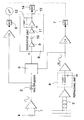
- the device comprises means for measuring the current of a phase, designated by I 1...n , referenced by the numeral 1 and suitable to measure the current of a phase of each motor sequentially, with multiplexing means 2 suitable to multiplex the various currents in order to then perform power calculation, as described in detail hereinafter.
- the device further comprises voltage measuring means, designated by the reference numeral 3, which are suitable to measure a voltage V of one of the phases R, S and T, or a line-to-line voltage between said phases, if the system is three-phase.
- the measurement of the current is phase shifted with respect to the measurement of the voltage obtained by the measuring means 3 not only due to the inductive nature of the load but also due to the possible phase shift between the current and the voltage being measured.
- rephasing means 4 are arranged in a cascade configuration with respect to the voltage measuring means 3 and are conveniently constituted by an RC circuit, which allows to introduce a preset phase shift ⁇ in the waveform of the measured voltage that it suitable to compensate for the advance of the line-to-line or concatenated voltage star with respect to the advance of the star voltages.
- the circuit according to the invention allows to obtain a current waveform with a corresponding voltage waveform of which a phase shift is already performed.
- multiplier means 5 which are suitable to emit in output a waveform determined by the product of the voltage and current waveforms, respectively, i.e., a waveform that indicates the apparent power.
- the waveform of the current and the waveform of the voltage are sent to respective A/D converters, designated by the reference numerals 6 and 7, which are interfaced with a microprocessor, which is adapted to coordinate the multiplexer 2 for selecting the currents I 1...n that arrive from the plurality of motors.
- Means 8 suitable to receive the active power are arranged in a cascade configuration with respect to the multiplier means 5 and comprise a first amplifier 9, a derivative unit 10, constituted for example by a capacitor, an inverter 11 that is cascade-connected to the capacitor 10, and an adder node A at which the waveform of the power in output from the inverter 11 is added to the waveform of the power in output from the amplifier 9.
- An amplifier having a limited passband (filter) 12 then allows to obtain in output the active power, designated by the reference numeral 13.
- the derivative unit allows to obtain a continuous power level, eliminating from the waveforms at the node C the harmonic component equal to VI cos [2( ⁇ t + ⁇ )].
- a microprocessor which is not shown and is interfaced with A/D converters 6, 7 and 14, divides, by performing appropriate software instructions and on the basis of the effective current and effective voltage, the active power into losses and mechanical power available at the motor shaft.
- the device according to the invention fully achieves the intended aim and objects, since it allows to measure the power sent to each motor without the aid of a microprocessor having complicated and expensive firmware, since the microprocessor in this case, only has to coordinate the currents that arrive from the various motors, and the operation for multiplying the voltage by the current for each motor is performed in multiplier means that are external to the microprocessors.
Landscapes
- Physics & Mathematics (AREA)
- General Physics & Mathematics (AREA)
- Engineering & Computer Science (AREA)
- Power Engineering (AREA)
- Control Of Ac Motors In General (AREA)
- Control Of Multiple Motors (AREA)
- Control Of Electric Motors In General (AREA)
Applications Claiming Priority (2)
| Application Number | Priority Date | Filing Date | Title |
|---|---|---|---|
| IT2001MI000331A ITMI20010331A1 (it) | 2001-02-16 | 2001-02-16 | Dispositivo per la misura di potenza per una pluralita' di motori avente costo ridotto |
| ITMI010331 | 2001-02-16 |
Publications (2)
| Publication Number | Publication Date |
|---|---|
| EP1235075A2 true EP1235075A2 (de) | 2002-08-28 |
| EP1235075A3 EP1235075A3 (de) | 2003-09-03 |
Family
ID=11446924
Family Applications (1)
| Application Number | Title | Priority Date | Filing Date |
|---|---|---|---|
| EP02000295A Withdrawn EP1235075A3 (de) | 2001-02-16 | 2002-01-16 | Einrichtung zum Messen der Leistung für Motoren |
Country Status (6)
| Country | Link |
|---|---|
| US (1) | US6703824B2 (de) |
| EP (1) | EP1235075A3 (de) |
| JP (1) | JP2002311067A (de) |
| KR (1) | KR20020067420A (de) |
| CN (1) | CN1217199C (de) |
| IT (1) | ITMI20010331A1 (de) |
Cited By (1)
| Publication number | Priority date | Publication date | Assignee | Title |
|---|---|---|---|---|
| EP3101435A1 (de) * | 2015-05-13 | 2016-12-07 | MediaTek Inc. | Leistungsdetektor |
Families Citing this family (5)
| Publication number | Priority date | Publication date | Assignee | Title |
|---|---|---|---|---|
| TWI260669B (en) * | 2005-07-26 | 2006-08-21 | Ind Tech Res Inst | Field emission light-emitting device |
| US8164298B2 (en) * | 2009-03-26 | 2012-04-24 | GM Global Technology Operations LLC | System and method for detecting loss of isolation while an AC motor is operating |
| KR101251794B1 (ko) * | 2011-09-30 | 2013-04-08 | 삼성전기주식회사 | 전력 측정 시스템 |
| TWI634748B (zh) | 2017-12-05 | 2018-09-01 | 財團法人工業技術研究院 | 量測系統及其鎖相迴路暨量測方法 |
| KR102917296B1 (ko) * | 2024-09-02 | 2026-01-26 | 단국대학교 산학협력단 | 잠긴 횡월류 상태에서의 횡월류량 연산 장치 및 방법 |
Family Cites Families (6)
| Publication number | Priority date | Publication date | Assignee | Title |
|---|---|---|---|---|
| IT1099456B (it) * | 1978-09-08 | 1985-09-18 | Cgs Apparecch | Strumento indicatore per misure di potenza elettrica provvisto di convertitore statico di misura |
| DE3151904C2 (de) * | 1981-12-30 | 1985-12-12 | Uranit GmbH, 5170 Jülich | Verfahren zum Optimieren der Leistungsaufnahme einer Vielzahl parallelgeschalteter Hysteresemotoren |
| US4989155A (en) * | 1986-08-14 | 1991-01-29 | Gte Valenite Corporation | Intelligent power monitor |
| US4896106A (en) * | 1987-09-21 | 1990-01-23 | Landis & Gyr Metering, Inc. | Watthour meter for wye connected systems |
| US5017860A (en) * | 1988-12-02 | 1991-05-21 | General Electric Company | Electronic meter digital phase compensation |
| DE19735022B4 (de) * | 1997-08-13 | 2008-09-04 | Bucyrus Dbt Europe Gmbh | Verfahren zur Ermittlung der Wirkleistung von Asynchron-Elektromotoren |
-
2001
- 2001-02-16 IT IT2001MI000331A patent/ITMI20010331A1/it unknown
-
2002
- 2002-01-16 EP EP02000295A patent/EP1235075A3/de not_active Withdrawn
- 2002-01-22 US US10/051,100 patent/US6703824B2/en not_active Expired - Fee Related
- 2002-01-25 KR KR1020020004409A patent/KR20020067420A/ko not_active Withdrawn
- 2002-02-08 CN CN021030782A patent/CN1217199C/zh not_active Expired - Fee Related
- 2002-02-15 JP JP2002038429A patent/JP2002311067A/ja active Pending
Cited By (2)
| Publication number | Priority date | Publication date | Assignee | Title |
|---|---|---|---|---|
| EP3101435A1 (de) * | 2015-05-13 | 2016-12-07 | MediaTek Inc. | Leistungsdetektor |
| US10082528B2 (en) | 2015-05-13 | 2018-09-25 | Mediatek Inc. | Power detector |
Also Published As
| Publication number | Publication date |
|---|---|
| JP2002311067A (ja) | 2002-10-23 |
| KR20020067420A (ko) | 2002-08-22 |
| ITMI20010331A1 (it) | 2002-08-16 |
| CN1375701A (zh) | 2002-10-23 |
| US20020113604A1 (en) | 2002-08-22 |
| EP1235075A3 (de) | 2003-09-03 |
| US6703824B2 (en) | 2004-03-09 |
| CN1217199C (zh) | 2005-08-31 |
Similar Documents
| Publication | Publication Date | Title |
|---|---|---|
| JP4202648B2 (ja) | 多相電動機の永久磁石回転子の角度位置を測定する方法 | |
| US5548197A (en) | Method and apparatus for determining motor speed using zero crossing times | |
| EP0660120A1 (de) | Verfahren zur digitalen elektronischen Messung periodischer elektrischer Grössen und Instrument zur Verwirklichung solcher Verfahren | |
| KR20170039274A (ko) | 오프셋 보상이 되는 홀 효과 센서 회로 | |
| US6703824B2 (en) | Low-cost power measurement device for a plurality of motors | |
| DE112015006003T5 (de) | Winkelfehlerkorrekturvorrichtung und Winkelfehlerkorrekturverfahren für einen Positionssensor | |
| US5619114A (en) | Signal averager for use with motor controller | |
| US11728755B2 (en) | Method for determining a rotor position of an electric rotating machine, and an electric rotating machine for carrying out a method of this kind | |
| CN112970188A (zh) | 位置推定装置和位置推定方法 | |
| US9250068B2 (en) | Rotation angle detecting device | |
| JP2014124075A (ja) | 逆起電力検出回路およびそれを用いたモーター駆動制御装置 | |
| US7906929B2 (en) | Method and device for controlling a three-phase machine having several phase windings, which can be controlled by means of pulse width modulation | |
| US4302712A (en) | Method of minimizing resonance in stepping motor and improved driver therefor | |
| EP2365633A1 (de) | Digital-umsetzungseinrichtung und stromumsetzungseinrichtung | |
| CN110895316A (zh) | 霍尔传感器电路、电机控制系统和霍尔元件感测方法 | |
| Schubert et al. | Gate driver integrated instantaneous phase voltage measurement in PWM voltage source inverters | |
| JPH09318678A (ja) | 交流計測方法及び装置 | |
| JP3625966B2 (ja) | 周波数測定装置 | |
| CN114070163B (zh) | 电机的控制方法、电机的控制装置及电机的控制模块 | |
| US20130207647A1 (en) | Method and device for the sensor-free position determination of an electronically commutated electric machine | |
| JP2004093416A (ja) | 電圧・電流計測装置 | |
| WO2021157000A1 (ja) | 角度検出装置 | |
| SU1326928A1 (ru) | Источник опорного сигнала к балансировочному станку | |
| SU1476591A1 (ru) | Многодвигательный электропривод | |
| SU436454A1 (ru) | Цифровой телевизионный фотоэлектрическийколориметр |
Legal Events
| Date | Code | Title | Description |
|---|---|---|---|
| PUAI | Public reference made under article 153(3) epc to a published international application that has entered the european phase |
Free format text: ORIGINAL CODE: 0009012 |
|
| AK | Designated contracting states |
Kind code of ref document: A2 Designated state(s): AT BE CH CY DE DK ES FI FR GB GR IE IT LI LU MC NL PT SE TR |
|
| AX | Request for extension of the european patent |
Free format text: AL;LT;LV;MK;RO;SI |
|
| PUAL | Search report despatched |
Free format text: ORIGINAL CODE: 0009013 |
|
| AK | Designated contracting states |
Kind code of ref document: A3 Designated state(s): AT BE CH CY DE DK ES FI FR GB GR IE IT LI LU MC NL PT SE TR |
|
| AX | Request for extension of the european patent |
Extension state: AL LT LV MK RO SI |
|
| 17P | Request for examination filed |
Effective date: 20040126 |
|
| 17Q | First examination report despatched |
Effective date: 20040329 |
|
| AKX | Designation fees paid |
Designated state(s): AT BE CH CY DE DK ES FI FR GB GR IE IT LI LU MC NL PT SE TR |
|
| RAP1 | Party data changed (applicant data changed or rights of an application transferred) |
Owner name: KYRO ITALY S.P.A. |
|
| RAP1 | Party data changed (applicant data changed or rights of an application transferred) |
Owner name: Z. BAVELLONI S.P.A. |
|
| GRAP | Despatch of communication of intention to grant a patent |
Free format text: ORIGINAL CODE: EPIDOSNIGR1 |
|
| STAA | Information on the status of an ep patent application or granted ep patent |
Free format text: STATUS: THE APPLICATION IS DEEMED TO BE WITHDRAWN |
|
| 18D | Application deemed to be withdrawn |
Effective date: 20060905 |