EP1235079A2 - Méthode de réduction d'interférence dans un dispostif radar et équipement radar - Google Patents
Méthode de réduction d'interférence dans un dispostif radar et équipement radar Download PDFInfo
- Publication number
- EP1235079A2 EP1235079A2 EP01129602A EP01129602A EP1235079A2 EP 1235079 A2 EP1235079 A2 EP 1235079A2 EP 01129602 A EP01129602 A EP 01129602A EP 01129602 A EP01129602 A EP 01129602A EP 1235079 A2 EP1235079 A2 EP 1235079A2
- Authority
- EP
- European Patent Office
- Prior art keywords
- frequency
- varied
- radar device
- carrier frequency
- pulse repetition
- Prior art date
- Legal status (The legal status is an assumption and is not a legal conclusion. Google has not performed a legal analysis and makes no representation as to the accuracy of the status listed.)
- Withdrawn
Links
- 238000000034 method Methods 0.000 title claims abstract description 26
- 230000001629 suppression Effects 0.000 claims description 3
- 238000011156 evaluation Methods 0.000 description 7
- 230000005540 biological transmission Effects 0.000 description 3
- 230000033228 biological regulation Effects 0.000 description 2
- 238000010586 diagram Methods 0.000 description 2
- 238000001228 spectrum Methods 0.000 description 2
- 239000000969 carrier Substances 0.000 description 1
- 238000006243 chemical reaction Methods 0.000 description 1
- 230000003111 delayed effect Effects 0.000 description 1
- 230000007257 malfunction Effects 0.000 description 1
- 238000012986 modification Methods 0.000 description 1
- 230000004048 modification Effects 0.000 description 1
- 238000012544 monitoring process Methods 0.000 description 1
- 230000036316 preload Effects 0.000 description 1
- 238000012545 processing Methods 0.000 description 1
- 230000002787 reinforcement Effects 0.000 description 1
Images




Classifications
-
- G—PHYSICS
- G01—MEASURING; TESTING
- G01S—RADIO DIRECTION-FINDING; RADIO NAVIGATION; DETERMINING DISTANCE OR VELOCITY BY USE OF RADIO WAVES; LOCATING OR PRESENCE-DETECTING BY USE OF THE REFLECTION OR RERADIATION OF RADIO WAVES; ANALOGOUS ARRANGEMENTS USING OTHER WAVES
- G01S13/00—Systems using the reflection or reradiation of radio waves, e.g. radar systems; Analogous systems using reflection or reradiation of waves whose nature or wavelength is irrelevant or unspecified
- G01S13/02—Systems using reflection of radio waves, e.g. primary radar systems; Analogous systems
- G01S13/06—Systems determining position data of a target
- G01S13/08—Systems for measuring distance only
- G01S13/10—Systems for measuring distance only using transmission of interrupted, pulse modulated waves
- G01S13/22—Systems for measuring distance only using transmission of interrupted, pulse modulated waves using irregular pulse repetition frequency
- G01S13/222—Systems for measuring distance only using transmission of interrupted, pulse modulated waves using irregular pulse repetition frequency using random or pseudorandom pulse repetition frequency
-
- G—PHYSICS
- G01—MEASURING; TESTING
- G01S—RADIO DIRECTION-FINDING; RADIO NAVIGATION; DETERMINING DISTANCE OR VELOCITY BY USE OF RADIO WAVES; LOCATING OR PRESENCE-DETECTING BY USE OF THE REFLECTION OR RERADIATION OF RADIO WAVES; ANALOGOUS ARRANGEMENTS USING OTHER WAVES
- G01S13/00—Systems using the reflection or reradiation of radio waves, e.g. radar systems; Analogous systems using reflection or reradiation of waves whose nature or wavelength is irrelevant or unspecified
- G01S13/02—Systems using reflection of radio waves, e.g. primary radar systems; Analogous systems
- G01S13/06—Systems determining position data of a target
- G01S13/08—Systems for measuring distance only
- G01S13/10—Systems for measuring distance only using transmission of interrupted, pulse modulated waves
- G01S13/22—Systems for measuring distance only using transmission of interrupted, pulse modulated waves using irregular pulse repetition frequency
- G01S13/225—Systems for measuring distance only using transmission of interrupted, pulse modulated waves using irregular pulse repetition frequency with cyclic repetition of a non-uniform pulse sequence, e.g. staggered PRF
-
- G—PHYSICS
- G01—MEASURING; TESTING
- G01S—RADIO DIRECTION-FINDING; RADIO NAVIGATION; DETERMINING DISTANCE OR VELOCITY BY USE OF RADIO WAVES; LOCATING OR PRESENCE-DETECTING BY USE OF THE REFLECTION OR RERADIATION OF RADIO WAVES; ANALOGOUS ARRANGEMENTS USING OTHER WAVES
- G01S13/00—Systems using the reflection or reradiation of radio waves, e.g. radar systems; Analogous systems using reflection or reradiation of waves whose nature or wavelength is irrelevant or unspecified
- G01S13/02—Systems using reflection of radio waves, e.g. primary radar systems; Analogous systems
- G01S13/06—Systems determining position data of a target
- G01S13/08—Systems for measuring distance only
- G01S13/10—Systems for measuring distance only using transmission of interrupted, pulse modulated waves
- G01S13/24—Systems for measuring distance only using transmission of interrupted, pulse modulated waves using frequency agility of carrier wave
Definitions
- the invention relates to a method for interference suppression Radar device in which signals with a carrier frequency be sent out and the signals pulsed with a pulse repetition frequency are sent out.
- the invention also relates to a radar device with means for sending signals with a carrier frequency and Means for pulsing the signals with a pulse repetition frequency.
- radar devices become electromagnetic Waves emitted by a transmitting antenna. To meet these electromagnetic waves on an obstacle, so they are reflected and after the reflection by one received another or the same antenna. Following the received signals are signal processing and signal evaluation supplied.
- radar sensors are used in motor vehicles for measuring the distance to targets and / or the relative speed regarding such goals outside the Motor vehicle used. For example, come as goals vehicles or facilities in front or parked on the street, pedestrians or cyclists in the area of the motor vehicle in question.
- FIG. 1 shows a schematic representation of a radar device with a correlation receiver of the stand of the technique.
- a transmitter 300 is powered by pulse generation 302 causes a transmission signal 306 via an antenna 304 radiate.
- the transmission signal 306 strikes a target object 308 where it is reflected.
- the receive signal 310 is received by antenna 312.
- This antenna 312 may be identical to antenna 304.
- After receiving of the received signal 310 by the antenna 312 becomes this transmitted to the receiver 314 and subsequently via a Unit 316 with low pass and analog / digital conversion a signal evaluation 318 fed.
- the peculiarity for the correlation receiver is that the Receiver 314 from pulse generation 302 generates a reference signal 320 receives. Those received by receiver 314 Received signals 310 are in the receiver 314 with the Reference signal 320 mixed.
- the correlation can based on the time delay from sending until receiving the radar pulses, for example the distance of a target object can be closed.
- the invention is based on a first embodiment the generic method in that the pulse repetition frequency during the operation of the radar device is varied. In this way it is possible to to eliminate the disadvantages mentioned. In particular can by varying the pulse repetition rate interference be eliminated.
- the carrier frequency during the operation of the radar device is varied. This is another way to different types of interference remove.
- the pulse repetition rate varies deterministically. That can vary for example, so that four different pulse repetition frequencies in a fixed order about also specified periods are used.
- the pulse repetition frequency is varied chaotically. This is a particularly safe one Possibility of variation, which in particular with regard for a potential deliberate interference with the radar unfolds their special advantages.
- the carrier frequency may be advantageous for the carrier frequency to pass through Phase modulation is varied. It refers to a suitable method for changing the broadcast Signals so that interference can ultimately be eliminated.
- a variation of the carrier frequency can have comparable advantages with frequency modulation.
- the carrier frequency by frequency modulation it is particularly advantageous that by mixing the received signal with the modulated one Carrier frequency generates a virtual intermediate frequency and that an evaluation of the received signal at the virtual intermediate frequency takes place.
- modulating the carrier frequency with a modulation frequency side lines are generated in the frequency spectrum. The The distance between these side lines corresponds to the modulation frequency. If the received signal is now with the modulated carrier frequency mixed, so can also a mix of these side lines.
- the useful signal which in the present case, for example Pulse spectrum appears on the side lines.
- this signal can be instead of evaluating the signal at a frequency of 0,
- the signal lying at the modulation frequency has a lower amplitude, but this is the case Noise in a receiver is essentially reversed proportional to the frequency.
- An evaluation at a Frequency of 0 thus generates a high noise component in the Receiver while an evaluation at the virtual Intermediate frequency, for example at 50 kHz, a reduced Brings noise component with it.
- frequency hopping can be used to vary the carrier frequency.
- the Frequency hopping, phase modulation and Frequency modulation can also be used mixed. When choosing the modulation frequency and the stroke When using frequency hopping, make sure that the modulation frequency or the stroke frequency are greater than the pulse repetition frequency.
- the invention builds on the generic method in that the Carrier frequency during the operation of the radar device is varied.
- the carrier frequency is therefore not additional to the pulse repetition rate varies. Rather it will the radar is sufficient by varying the carrier frequency suppressed.
- the invention builds on the generic radar device in a first embodiment in that Means for varying the pulse repetition rate during operation are provided. By varying the Pulse repetition rate can cause interference during operation be eliminated.
- the pulse repetition frequency is deterministic is varied. Different pulse repetition frequencies can, for example, in a fixed order be used over specified periods.
- the pulse repetition frequency is varied chaotically.
- the radar device is preferably developed in such a way that that the carrier frequency by phase modulation is varied. This is an exemplary modulation process with which interference is ultimately eliminated can.
- the carrier frequency is varied by frequency modulation.
- the radar device is in the way advantageously further developed that the carrier frequency by Frequency modulation is varied by mixing the received signal with the modulated carrier frequency a virtual intermediate frequency is generated and that an evaluation of the received signal in the virtual Intermediate frequency takes place. You work with that a signal of lower intensity. Due to the However, evaluation at the intermediate frequency results Advantages due to less receiver noise.
- the carrier frequency by frequency hopping is varied.
- the different modulation methods that is phase modulation and frequency modulation, can also be used mixed. Likewise can be a mix with a frequency hopping method respectively. Care should be taken that the modulation frequency or the stroke frequency are greater than the pulse repetition rate to avoid gaps.
- the radar device is built of the present invention on the generic Radar device on that means for varying the carrier frequency is provided during operation are. So it is not essential to determine the carrier frequency to vary in addition to the pulse repetition rate. Rather, the radar can adequately by a Variation of the carrier frequency can be suppressed.
- the invention is based on the finding that through Variation of the center frequency or the pulse repetition rate Sending properties can be generated also comply with strict approval regulations. Further an interference-free radar can be made available, which is neither intentional nor unintentional in its Function is affected.
- FIG. 2 shows a motor vehicle 10 on which a plurality of radar sensors 12 are arranged.
- the radar sensors are with each other and with a bus concept Control and monitoring units connected, in particular a unit 14 for providing a parking aid and to detect a blind spot, one unit 16 for the pre-crash function and a unit 18 for stop & Go are provided.
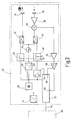
- FIG. 3 schematically shows the structure of a sensor 20, which is used in the vicinity of the radar.
- the sensor 20 is an electronic control unit 22 Voltage provided, for example a Voltage of 8 V. This voltage is in a DC-DC converter 24 transformed so that ultimately the supply voltage available for the sensor components is set, for example 5 V.
- a carrier frequency of for example 24 GHz is from a local oscillator 26 delivered.
- This local oscillator 26 is equipped with a Preload, which ultimately comes from the one Clock generator 28 made available by means of pulses a converter 30 is generated.
- the clock generator 28 generated pulses for example a frequency of 5 MHz can be used to modulate the Local oscillator 26 provided carrier signals used.
- This modulation takes place in the transmission branch by the switch 32, which is provided by a pulse shaper 46 is switched.
- the pulse shaper 46 is in turn from the clock frequency of the clock generator 28 driven.
- the Pulsed signals thus generated are generated by the antenna 34 sent out. In the event of a reflection of the signals which are transmitted by the antenna 34, these will received by the receiving antenna 36.
- After reinforcement of the received signals in an amplifier 38 are the Signals fed to a mixer 40.
- the switch is from a pulse generator 48 driven, which with respect to pulses output by the pulse generator 46 by a delay ⁇ t outputs delayed pulses. This delay is available through a delay circuit 50 posed.
- a microcontroller 52 which one digital signal processor has the delay delay circuit 50. This happens via a first analog output 54 of the microcontroller 52. Be through a second analog output 60 the output signals processed by an amplifier 56 the mixer 40 by further variable gain in the Amplifier 58 affects. Influencing this variable Amplifier 58 takes place by means of a second analog Output 60 of the microcontroller 52. The output signal of variable amplifier 58 becomes an analog Input 62 of the microcontroller 52 supplied.
- the microcontroller 52 communicates via an input-output bus 64 (I / O bus) with the electronic control unit 22.
- FIG. 4 shows a block diagram of a radar device, which largely corresponds to the block diagram according to FIG. 3 equivalent.
- the radar device be suppressed.
- Figure 5 also largely corresponds to the representation according to Figure 3.
- additional means 68 for modulating the carrier frequency is provided. That way too it is possible to suppress the radar device.
- the embodiments can be combined according to Figure 4 and Figure 5, the is called both the pulse repetition frequency and the carrier frequency are modulated.
Landscapes
- Engineering & Computer Science (AREA)
- Radar, Positioning & Navigation (AREA)
- Remote Sensing (AREA)
- Computer Networks & Wireless Communication (AREA)
- Physics & Mathematics (AREA)
- General Physics & Mathematics (AREA)
- Radar Systems Or Details Thereof (AREA)
Applications Claiming Priority (2)
| Application Number | Priority Date | Filing Date | Title |
|---|---|---|---|
| DE10108584A DE10108584A1 (de) | 2001-02-22 | 2001-02-22 | Verfahren zum Entstören einer Radareinrichtung und Radareinrichtung |
| DE10108584 | 2001-02-22 |
Publications (2)
| Publication Number | Publication Date |
|---|---|
| EP1235079A2 true EP1235079A2 (fr) | 2002-08-28 |
| EP1235079A3 EP1235079A3 (fr) | 2004-06-23 |
Family
ID=7675145
Family Applications (1)
| Application Number | Title | Priority Date | Filing Date |
|---|---|---|---|
| EP01129602A Withdrawn EP1235079A3 (fr) | 2001-02-22 | 2001-12-12 | Méthode de réduction d'interférence dans un dispostif radar et équipement radar |
Country Status (3)
| Country | Link |
|---|---|
| US (1) | US6867730B2 (fr) |
| EP (1) | EP1235079A3 (fr) |
| DE (1) | DE10108584A1 (fr) |
Cited By (4)
| Publication number | Priority date | Publication date | Assignee | Title |
|---|---|---|---|---|
| DE102004050627A1 (de) * | 2004-10-18 | 2006-04-20 | Audi Ag | Verfahren und Entfernungsmessvorrichtung zum Bestimmen der Entfernung zwischen einem Objekt und der Vorrichtung |
| EP1775600A4 (fr) * | 2004-08-02 | 2007-09-05 | Mitsubishi Electric Corp | Appareil radar |
| CN102628943A (zh) * | 2012-05-08 | 2012-08-08 | 江苏经贸职业技术学院 | 基于恒指数谱混沌信号源的汽车防撞雷达 |
| WO2013076122A1 (fr) * | 2011-11-24 | 2013-05-30 | Hella Kgaa Hueck & Co. | Procédé de détermination d'au moins un paramètre aux fins de corrélation de deux objets |
Families Citing this family (18)
| Publication number | Priority date | Publication date | Assignee | Title |
|---|---|---|---|---|
| DE10142170A1 (de) * | 2001-08-29 | 2003-03-20 | Bosch Gmbh Robert | Pulsradaranordnung |
| EP1324069B1 (fr) * | 2001-12-21 | 2009-09-02 | STMicroelectronics S.r.l. | Dispositif de détection des distances utilisant des signaux chaotiques |
| JP2003347926A (ja) * | 2002-05-30 | 2003-12-05 | Sony Corp | レベルシフト回路、表示装置および携帯端末 |
| JP3688255B2 (ja) * | 2002-09-20 | 2005-08-24 | 株式会社日立製作所 | 車載用電波レーダ装置及びその信号処理方法 |
| US7126526B2 (en) | 2003-08-25 | 2006-10-24 | Lockheed Martin Corporation | Phased null radar |
| US7151483B2 (en) * | 2004-05-03 | 2006-12-19 | Raytheon Company | System and method for concurrent operation of multiple radar or active sonar systems on a common frequency |
| DE112006001114T5 (de) * | 2005-05-16 | 2008-04-30 | Murata Manufacturing Co. Ltd. | Radargerät |
| JP5226185B2 (ja) * | 2006-02-15 | 2013-07-03 | 富士通株式会社 | 探知測距装置 |
| CN100575984C (zh) * | 2006-06-14 | 2009-12-30 | 中国科学院电子学研究所 | 一种使用混沌信号的合成孔径雷达系统 |
| US20080278371A1 (en) * | 2007-05-11 | 2008-11-13 | Honeywell International Inc. | Methods and systems for reducing acquisition time in airborne weather radar |
| DE102009057191A1 (de) * | 2009-12-05 | 2011-06-09 | Valeo Schalter Und Sensoren Gmbh | Verfahren zum eindeutigen Bestimmen einer Entfernung und/oder einer relativen Geschwindigkeit eines Objektes, Fahrerassistenzeinrichtung und Kraftfahrzeug |
| US9746366B2 (en) | 2014-12-01 | 2017-08-29 | Rosemount Tank Radar Ab | Radar level gauging |
| US20160195607A1 (en) * | 2015-01-06 | 2016-07-07 | Radar Obstacle Detection Ltd. | Short-ragne obstacle detection radar using stepped frequency pulse train |
| US10379201B2 (en) * | 2016-10-26 | 2019-08-13 | GM Global Technology Operations LLC | Radar interference mitigation and collaborative operation |
| EP3410150B1 (fr) * | 2017-05-30 | 2022-01-19 | Nxp B.V. | Appareil de détection et de télémétrie |
| US11099264B2 (en) * | 2017-09-20 | 2021-08-24 | Motional Ad Llc | Variable range and frame-rate radar operation for automated vehicle |
| US11294029B2 (en) * | 2019-04-16 | 2022-04-05 | GM Global Technology Operations LLC | Radar system and method for updating waveform parameters |
| CN111856458B (zh) * | 2020-06-17 | 2023-06-23 | 西安电子科技大学 | 基于非走-停模式的星载双基sar回波时延计算方法 |
Citations (2)
| Publication number | Priority date | Publication date | Assignee | Title |
|---|---|---|---|---|
| US3354456A (en) * | 1964-10-30 | 1967-11-21 | Cutler Hammer Inc | Pulse-type object detection apparatus |
| US3969725A (en) * | 1974-06-12 | 1976-07-13 | The United States Of America As Represented By The Secretary Of Transportation | Distance measuring equipment |
Family Cites Families (15)
| Publication number | Priority date | Publication date | Assignee | Title |
|---|---|---|---|---|
| FR2278204A1 (fr) * | 1974-07-12 | 1976-02-06 | Thomson Csf | Dispositif integrateur multiple et systeme radar a impulsions a frequences multiples comportant un tel dispositif |
| GB1528164A (en) * | 1975-05-14 | 1978-10-11 | Marconi Co Ltd | Radar |
| US4387373A (en) * | 1977-04-21 | 1983-06-07 | Westinghouse Electric Corp. | Synthetic monopulse radar |
| FR2462716A1 (fr) * | 1979-07-31 | 1981-02-13 | Thomson Csf Mat Tel | Radar doppler coherent a impulsions a agilites de frequence |
| US4717917A (en) * | 1985-06-26 | 1988-01-05 | Rockwell International Corporation | Alien radar suppression circuit |
| DE3617440A1 (de) * | 1986-05-23 | 1987-11-26 | Messerschmitt Boelkow Blohm | Radar-hoehenmesser |
| US4914441A (en) * | 1988-08-29 | 1990-04-03 | Raytheon Company | Method of processing in a pulse doppler radar |
| SE467227B (sv) * | 1989-09-12 | 1992-06-15 | Nobeltech Systems Ab | Radaranordning som kontinuerligt utsaender en modulerad baervaagssignal |
| EP0444458A3 (en) * | 1990-03-02 | 1993-02-24 | Siemens Aktiengesellschaft | Pulsdopplerradar |
| US5608758A (en) * | 1992-07-15 | 1997-03-04 | Futaba Denshi Kogyo, K.K. | Radio control device having crystal high frequency module and high frequency phase lockloop for selective use, modules detachably mounted |
| US5537117A (en) * | 1995-08-08 | 1996-07-16 | Litton Systems, Inc. | Closed loop countermeasure to passive direction finding and location of radar transmitters using Doppler techniques |
| US6148020A (en) * | 1996-03-22 | 2000-11-14 | Sanyo Electric Co., Ltd. | Method and device for frequency hopping communication by changing a carrier frequency |
| US6049561A (en) * | 1997-04-30 | 2000-04-11 | Raytheon Company | Radio frequency communication system |
| JP2942923B2 (ja) * | 1997-11-27 | 1999-08-30 | 株式会社ジーデイーエス | ランダムパルス型レーダー装置 |
| US6049302A (en) * | 1999-05-04 | 2000-04-11 | Boeing North American | Pulsed doppler radar system with small intermediate frequency filters |
-
2001
- 2001-02-22 DE DE10108584A patent/DE10108584A1/de not_active Withdrawn
- 2001-12-12 EP EP01129602A patent/EP1235079A3/fr not_active Withdrawn
-
2002
- 2002-02-22 US US10/080,650 patent/US6867730B2/en not_active Expired - Fee Related
Patent Citations (2)
| Publication number | Priority date | Publication date | Assignee | Title |
|---|---|---|---|---|
| US3354456A (en) * | 1964-10-30 | 1967-11-21 | Cutler Hammer Inc | Pulse-type object detection apparatus |
| US3969725A (en) * | 1974-06-12 | 1976-07-13 | The United States Of America As Represented By The Secretary Of Transportation | Distance measuring equipment |
Cited By (8)
| Publication number | Priority date | Publication date | Assignee | Title |
|---|---|---|---|---|
| EP1775600A4 (fr) * | 2004-08-02 | 2007-09-05 | Mitsubishi Electric Corp | Appareil radar |
| DE102004050627A1 (de) * | 2004-10-18 | 2006-04-20 | Audi Ag | Verfahren und Entfernungsmessvorrichtung zum Bestimmen der Entfernung zwischen einem Objekt und der Vorrichtung |
| DE102004050627B4 (de) * | 2004-10-18 | 2013-08-08 | Audi Ag | Verfahren und Entfernungsmessvorrichtung zum Bestimmen der Entfernung zwischen einem Objekt und der Vorrichtung |
| WO2013076122A1 (fr) * | 2011-11-24 | 2013-05-30 | Hella Kgaa Hueck & Co. | Procédé de détermination d'au moins un paramètre aux fins de corrélation de deux objets |
| CN104054004A (zh) * | 2011-11-24 | 2014-09-17 | 黑拉许克联合股份有限公司 | 用于确定至少一个关联两个对象用的参数的方法 |
| CN104054004B (zh) * | 2011-11-24 | 2017-04-19 | 黑拉许克联合股份有限公司 | 用于确定至少一个关联两个对象用的参数的方法 |
| US9678203B2 (en) | 2011-11-24 | 2017-06-13 | Hella Kgaa Hueck & Co. | Method for determining at least one parameter for the purpose of correlating two objects |
| CN102628943A (zh) * | 2012-05-08 | 2012-08-08 | 江苏经贸职业技术学院 | 基于恒指数谱混沌信号源的汽车防撞雷达 |
Also Published As
| Publication number | Publication date |
|---|---|
| EP1235079A3 (fr) | 2004-06-23 |
| DE10108584A1 (de) | 2002-09-05 |
| US6867730B2 (en) | 2005-03-15 |
| US20020130810A1 (en) | 2002-09-19 |
Similar Documents
| Publication | Publication Date | Title |
|---|---|---|
| EP1235079A2 (fr) | Méthode de réduction d'interférence dans un dispostif radar et équipement radar | |
| EP1235078A2 (fr) | Procédé de détection de défaut d'un système radar et système radar | |
| DE102007013266B4 (de) | Radarvorrichtung | |
| EP1562050B1 (fr) | Procédé et dispositif pour adapter un seuil dans un disposif de détection | |
| EP1340097B1 (fr) | Dispositif radar et son procede de fonctionnement | |
| DE102013218571A1 (de) | Vorrichtung und Verfahren zur seitlichen Umfelderfassung eines Kraftfahrzeugs | |
| DE10345565B4 (de) | Impulsradarvorrichtung | |
| DE19924755A1 (de) | Abstandserfassungsvorrichtung | |
| EP3906421B1 (fr) | Procédé pour faire fonctionner un dispositif de contrôle pour tester un capteur de distance fonctionnant avec des ondes électromagnétiques et dispositif de contrôle correspondant | |
| DE10208332A1 (de) | Pulsradarvorrichtung und Verfahren zum Erfassen, zum Detektieren und/oder zum Auswerten von mindestens einem Objekt | |
| DE19963005A1 (de) | Verfahren und Vorrichtung zur Erfassung und Auswertung von Objekten im Umgebungsbereich eines Fahrzeuges | |
| DE3028338A1 (de) | Doppler-radareinrichtung | |
| DE102004062023B4 (de) | Radarsystem zur Überwachung von Zielen in verschiedenen Entfernungsbereichen | |
| EP1516200B1 (fr) | Procede et dispositif pour produire des signaux hf qui servent a determiner la distance a laquelle se trouve un objet et/ou sa vitesse | |
| DE19902076B4 (de) | Sensor zum Messen eines Abstands zu einem Objekt | |
| EP1449008B1 (fr) | Radar a onde continue a modulation de frequence (fmcw), avec limitation du temps d'emission pour eviter les effets de repliement de spectre | |
| DE19631590C2 (de) | Verfahren zur Behandlung von Störsignalen bei einem Kraftfahrzeug-Radarsystem und Kraftfahrzeug-Radarsystem hierfür | |
| EP2223154B1 (fr) | Ensemble de détection radar | |
| DE19806592A1 (de) | Mikrowellen-Bewegungssensor | |
| WO2002054106A1 (fr) | Dispositif et procede de detection d'objets fixes ou mobiles par rayonnement radar | |
| EP4679138A1 (fr) | Procédé de mesure de distance par ultrasons | |
| EP1102089B1 (fr) | Méthode et dispositif pour déterminer la distance à un objet employant un signal électromagnétique à impulsions | |
| DE102024119909A1 (de) | Verfahren zur Ultraschallabstandsmessung | |
| DE2317465C3 (de) | Vorrichtung zum Vorbestimmen von FahrzeugzusammenstöOen | |
| DE10249707A1 (de) | Pulsradaranordnung |
Legal Events
| Date | Code | Title | Description |
|---|---|---|---|
| PUAI | Public reference made under article 153(3) epc to a published international application that has entered the european phase |
Free format text: ORIGINAL CODE: 0009012 |
|
| AK | Designated contracting states |
Kind code of ref document: A2 Designated state(s): AT BE CH CY DE DK ES FI FR GB GR IE IT LI LU MC NL PT SE TR |
|
| AX | Request for extension of the european patent |
Free format text: AL;LT;LV;MK;RO;SI |
|
| PUAL | Search report despatched |
Free format text: ORIGINAL CODE: 0009013 |
|
| AK | Designated contracting states |
Kind code of ref document: A3 Designated state(s): AT BE CH CY DE DK ES FI FR GB GR IE IT LI LU MC NL PT SE TR |
|
| AX | Request for extension of the european patent |
Extension state: AL LT LV MK RO SI |
|
| RIC1 | Information provided on ipc code assigned before grant |
Ipc: 7G 01S 13/93 B Ipc: 7G 01S 13/26 B Ipc: 7G 01S 13/24 B Ipc: 7G 01S 13/22 B Ipc: 7G 01S 7/36 A |
|
| 17P | Request for examination filed |
Effective date: 20041223 |
|
| AKX | Designation fees paid |
Designated state(s): DE FR GB IT SE |
|
| 17Q | First examination report despatched |
Effective date: 20050209 |
|
| STAA | Information on the status of an ep patent application or granted ep patent |
Free format text: STATUS: THE APPLICATION IS DEEMED TO BE WITHDRAWN |
|
| 18D | Application deemed to be withdrawn |
Effective date: 20060527 |