EP1235247B1 - Support pour plusieurs fusibles - Google Patents
Support pour plusieurs fusibles Download PDFInfo
- Publication number
- EP1235247B1 EP1235247B1 EP02003842A EP02003842A EP1235247B1 EP 1235247 B1 EP1235247 B1 EP 1235247B1 EP 02003842 A EP02003842 A EP 02003842A EP 02003842 A EP02003842 A EP 02003842A EP 1235247 B1 EP1235247 B1 EP 1235247B1
- Authority
- EP
- European Patent Office
- Prior art keywords
- holder
- fuse
- fuse holder
- housing
- contact
- Prior art date
- Legal status (The legal status is an assumption and is not a legal conclusion. Google has not performed a legal analysis and makes no representation as to the accuracy of the status listed.)
- Expired - Lifetime
Links
Images


Classifications
-
- H—ELECTRICITY
- H01—ELECTRIC ELEMENTS
- H01H—ELECTRIC SWITCHES; RELAYS; SELECTORS; EMERGENCY PROTECTIVE DEVICES
- H01H85/00—Protective devices in which the current flows through a part of fusible material and this current is interrupted by displacement of the fusible material when this current becomes excessive
- H01H85/02—Details
- H01H85/20—Bases for supporting the fuse; Separate parts thereof
- H01H85/203—Bases for supporting the fuse; Separate parts thereof for fuses with blade type terminals
- H01H85/2035—Bases for supporting the fuse; Separate parts thereof for fuses with blade type terminals for miniature fuses with parallel side contacts
-
- H—ELECTRICITY
- H01—ELECTRIC ELEMENTS
- H01H—ELECTRIC SWITCHES; RELAYS; SELECTORS; EMERGENCY PROTECTIVE DEVICES
- H01H85/00—Protective devices in which the current flows through a part of fusible material and this current is interrupted by displacement of the fusible material when this current becomes excessive
- H01H85/02—Details
- H01H85/20—Bases for supporting the fuse; Separate parts thereof
- H01H2085/2085—Holders for mounting a fuse on a printed circuit
-
- H—ELECTRICITY
- H01—ELECTRIC ELEMENTS
- H01H—ELECTRIC SWITCHES; RELAYS; SELECTORS; EMERGENCY PROTECTIVE DEVICES
- H01H85/00—Protective devices in which the current flows through a part of fusible material and this current is interrupted by displacement of the fusible material when this current becomes excessive
- H01H85/02—Details
- H01H85/20—Bases for supporting the fuse; Separate parts thereof
- H01H2085/209—Modular assembly of fuses or holders, e.g. side by side; combination of a plurality of identical fuse units
-
- Y—GENERAL TAGGING OF NEW TECHNOLOGICAL DEVELOPMENTS; GENERAL TAGGING OF CROSS-SECTIONAL TECHNOLOGIES SPANNING OVER SEVERAL SECTIONS OF THE IPC; TECHNICAL SUBJECTS COVERED BY FORMER USPC CROSS-REFERENCE ART COLLECTIONS [XRACs] AND DIGESTS
- Y10—TECHNICAL SUBJECTS COVERED BY FORMER USPC
- Y10S—TECHNICAL SUBJECTS COVERED BY FORMER USPC CROSS-REFERENCE ART COLLECTIONS [XRACs] AND DIGESTS
- Y10S439/00—Electrical connectors
- Y10S439/933—Special insulation
- Y10S439/937—Plural insulators in strip form
Definitions
- the present invention belongs to a field of fuse holder into which a blade type fuse, with blade terminals protruding from its body, is fitted.
- a fuse fitting device into which a blade type fuse is fitted is known.
- This device comprises a block of synthetic resin, and connecting terminals, which are inserted from below into a chamber in the block and fitted to a lance of the block.
- electric wires are connected to the connecting terminals, these connecting terminals are inserted into the chamber of the block and fitted to the lance, a fuse is inserted from above into the chamber of the block, and the blade terminals of the fuse are fitted into the connecting terminals to make connection (for example, refer to Japanese Patent unexamined publication gazette Heisei 6-150806 ).
- the closest prior art document US-A-5 281 171 discloses a fuse holder into which a blade type fuse, with blade terminals protruding from the body thereof, is fitted, said fuse holder comprising a holder housing comprising a chamber for holding the blade terminals and at least a part of the body of a fuse inserted from above is formed with wide walls at the front and the rear and narrow walls on the right and the left, and contacts, which are provided two for the holder housing, each contact having an intermediate part fixed to the holder housing, a connecting part, at one end of the contact, extending into the chamber to fit with a blade terminal, and a leg, at the other end of the contact, extending out of the holder housing to be soldered or press-fitted onto a printed circuit board.
- the connecting part of the contact is formed into a fork shape, which can be expanded towards the front wall and the rear wall of the holder housing, and the clearances between the connecting part and the front wall and the rear wall are set in such way that they allow deformation of the connecting part while limiting excessive deformation.
- the intermediate parts of the contacts are press-fitted Into a space along the walls of the holder housing.
- the bottom of the holder housing is provided with two bosses in positions that are asymmetric to each other in relation to a line, which runs, when seen from the bottom, between the front wall and the rear wall of the housing approximately in parallel with these walls.
- US-A-1 952 554 discloses a multiple-connector holder comprising a plurality of connectors fitted in the multiple-connector holder and a holder group wherein a plurality of holder housings are arranged at a constant pitch and each pair of adjacent holder housings are coupled together by coupling parts each of which is integrally formed on a part of a wall thereof.
- the coupling parts have a strength that can maintain the pitch between adjacent two holder housings and yet can be broken by human force.
- the coupling parts are provided at a plurality of points on the wall.
- US-A-3 046 516 discloses a multiple-connector holder wherein a coupling part is provided at a single point on the wall and a holder housing group comprises twelve holder housings coupled together.
- US-A-6 089 918 discloses a fuse holder (adapter) wherein intermediate parts of the contacts are enveloped-cast in the holder housing.
- US-A-5 752 856 discloses a fuse holder wherein a leg of a contact is forked into two branches.
- US-A-5 409 399 discloses a connector assembly mounted in a PCB wherein a protrusion is formed in a leg of a contact.
- DE 25 11 459 A discloses a fuse holder wherein a holder housing has the same colour as that of a body of a fuse.
- US-A-5 926 952 discloses a method of producing a connector, wherein one single core having two metal terminals press-fitted therein closely fits in the open end (via a hood portion and a flange) of a tubular portion to thereby seal the interior thereof.
- US-A-5 926 952 discloses the possibility to fit parts of metal terminals into one core molded of resin and to fit this core in the open end of a tubular portion.
- a multiple-fuse holder wherein the intermediate part of the contact is envelope-cast in an insert and this insert is fitted into a space among the walls of the holder housing and wherein two of the inserts are coupled together (by a bridge).
- a fuse fitting device can be produced easily for any number of fuses to be used by properly dividing the multiple-fuse holder of the present invention or keeping it intact, mounting the fuse holders onto a printed circuit board and loading the printed circuit board in a casing or the like, and in turn, the production cost of the fuse fitting device can be reduced.
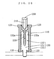
- a fuse to be fitted into this multiple-fuse holder is a blade type fuse 200, as shown in Fig. 13 and Fig. 14 or Fig. 27 and Fig. 28, with two blade terminals 220 protruding from the body 210 thereof.
- These fuses 200 have been standardized.
- the larger fuse 200 shown in Fig. 13 and Fig. 14 is called the maxi type, and the smaller fuse 200 shown in Fig. 27 and Fig. 28 is called the mini type.
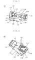
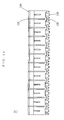
- Fig. 1 through Fig. 4 show a multiple-fuse holder H of the first example.
- a plurality of fuses 200 of the maxi type are fitted into this multiple-fuse holder H.
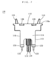
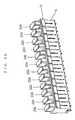
- the multiple-fuse holder H comprises a holder housing group h, which is a plurality of holder housings 100 being made of an insulator, arranged in a row and coupled together, and contacts 130, which are made of a conductor and are provided two for each holder housing 110.
- the holder housing 110 is provided with wide walls 111, 112 at the front and the rear, and narrow walls 113, 114 on the left and the right thereof.
- a chamber 115 which is through from the top 110a to the bottom 110b of the holder housing 110, is formed on the inner sides of the front wall 111, the rear wall 112, the left wall 113 and the right wall 114.
- the front, rear, left and right herein are used for convenience to indicate relative positional relationships. Accordingly, these directions are not related to the orientation of a printed circuit board 300, onto which the fuse holder 100 is to be mounted, and to the orientation of the casing or the like, into which the printed circuit board 300 is to be loaded.
- the blade terminals 220 of the fuse 200 and at least a part of the body 210 thereof will be held in the chamber 115.
- a portion of the holder housing 110 from a point between the top 110a and the bottom 110b and to the top 110a overhangs in the direction of alignment of the blade terminals 220.
- the body 210 of the fuse 200 is held by a horizontal wall 110c, which is inside the overhanging part.
- the holder housing group h is formed by placing a plurality of holder housings 110 at a regular pitch and coupling each pair of adjacent holder housings 110 by means of coupling parts 120.
- Each coupling part 120 is integrally formed on a part of a wall of each holder housing 110.
- a plurality of the holder housings 110 are placed at a regular pitch in such a way that, of each pair of adjacent holder housings 110, the front wall 111 of one holder housing 110 opposes the rear wall 112 of the other holder housing 110.
- the coupling part 120 is integrally formed on a part of the front wall 111 of each holder housing 110, and the coupling part 120 is integrally formed on a part of the rear wall 112 of each holder housing 110. Moreover, the coupling part 120 of the front wall 111 is integrally formed on the rear wall 112 of the holder housing 110 on the front side, and the coupling part 120 of the rear wall 112 is integrally formed on the front wall 111 of the holder housing 110 on the rear side.
- the open front wall 111 or the open rear wall 112 of the holder housing 110 at two ends of the holder housing group h is not provided with the coupling part 120.
- the coupling parts 120 are formed simultaneously when, for example, the holder housing group h is formed, by forming coupling parts 120 simultaneously with the holder housings 110.
- the coupling parts 120 have such a strength that they can maintain the pitch between two adjacent holder housings 110 and yet can be broken by human force.
- the strength that can maintain the pitch between two holder housings 110 is, for example, a strength of maintaining the pitch without being broken when the holder housings 110 are mounted onto a printed circuit board 300, when a fuse 200 is fitted into or removed from the holder housing 110, or when the holder housings 110 are transported.
- the strength that can be broken by human force is the strength that can be broken when subjected to pulling or twisting by a hand or the strength that can be broken by a manually operated tool such as a knife.
- the coupling parts 120 are provided at a plurality of points on both the front wall 111 and the rear wall 112. For example, at a total of four points; at one point on the left and on the right at the top 110a, and at one point on the right and on the left at the bottom 110b.
- the holder housing group h is formed by coupling twelve holder housings 110.
- the positions of the coupling parts 120 are not limited to both the front wall 111 and the rear wall 112. There are examples wherein the coupling parts are provided on the left wall 113 and the right wall 114, and examples wherein these features are combined together.
- Ribs 211 are formed on the side edges of the body 210 of the fuse 200 in parallel with the extending direction of the blade terminals 220.
- a U-shaped supporting part 116 which fits with the rib 211 of the body 210 of the fuse 200, is provided on the top of the left wall 113 and the right wall 114 of the holder housing 110.
- a slit 117 into which a side edge 221 of a blade terminal 220 will fit is provided in the left wall 113 and the right wall 114 of the holder housing 110.
- Two bosses 118, 119 are provided on the bottom 110b of the holder housing 110.
- the bosses 118, 119 are provided in positions that are asymmetric to each other in relation to a line L, which runs, when seen from the bottom, between the front wall 111 and the rear wall 112 approximately in parallel with these walls.
- each contact 130 is fixed to the bottom 110b of the holder housing 110.
- a fork-shaped connecting part 132 is provided on one end of the contact 130 to extend towards the inside of the chamber 115.
- This connecting part 132 is formed approximately into a U shape, and its two branches 132a are arranged to expand towards the front wall 111 and the rear wall 112 to fit with the blade terminal 220 with a certain contact pressure.
- a leg 133 is provided on the other end of the contact 130 to extend out of the holder housing 110. This leg 133 is soldered or press-fitted onto a printed circuit board 300.
- the intermediate part 131 of the contact 130 is press-fitted into a space between the walls 111, 112 at the bottom 110b of the holder housing 110.
- the leg 133 of the contact 130 is forked into two branches. In other words, it has two ends.
- the clearances t between the connecting part 132 and the front wall 111 and the rear wall 112 of the holder housing 110 are set in such a way that they allow deformation of the connecting part 132 while limiting its excessive deformation.
- the clearances t are provided not to hinder expansion of the two branches 132a of the connecting part 132 when they are properly pushed by the blade terminal 220 to expand towards the front wall 111 and the rear wall 112.
- the clearances t are provided to hold and prevent excessive deformation of the two branches 132a when they are pried by the blade terminal 220.
- a multiple-fuse holder H or a plurality of multiple-fuse holders H or a fuse holder 100 or a plurality of fuse holders 100 may be mounted onto the printed circuit board 300 before fitting a fuse 200 into each fuse holder 100.
- the configuration of the connecting part of the contact is not limited.
- the connecting part is formed with a coiled spring and the contact pressure between the contact and the blade terminal is secured by the coiled spring.
- the connecting part 132 of the contact 130 is formed into a fork shape that can expand towards the front wall 111 and the rear wall 112, and the clearances t between the connecting part 132 and the front wall 111 and the rear wall 112 of the holder housing 110 are set to allow deformation of the connecting part 132 while limiting its excessive deformation.
- the connecting part 132 of the contact 130 When the connecting part 132 of the contact 130 is deformed, the connecting part 132 will be restrained from excessive deformation by the front wall 111 and the rear wall 112 of the holder housing 110, and in turn, the connecting part 132 will be prevented from being pried by the blade terminal 220.
- the configuration of the coupling parts 120 is not limited.
- the coupling part 120 has a strength that can maintain the pitch between adjacent two holder housings 110 and yet can be broken by human power. With these arrangements, the coupling parts 120 will be broken when subjected to pulling, twisting or the like by human hands, and the coupling parts 120 can be broken by manually operated tools such as a knife. Thus the multiple-fuse holder H can be divided with ease. Moreover, as the coupling parts 120 will maintain the pitch between adjacent two holder housings 110, the respective fuse holders 110 can be mounted accurately onto a printed circuit board 300.
- the coupling parts 120 are provided at a plurality of points on the front wall 111 and the rear wall 112. With this arrangement, the strength of the coupling parts against twisting will be improved, and this is desirable under conditions in which the coupling parts 120 are subjected to twisting forces in production or in use.
- the number of holder housings that constitute a holder housing group is not limited.
- the holder housing group h comprises twelve holder housings 110 coupled together. With this arrangement, the multiple-fuse holder H can be utilized effectively, without generating any odd or waste, by dividing it when the number of fuses 200 to be used is 12, 6, 4, 3, 2 or 1.
- the holder housing is not provided with a supporting part.
- a supporting part 116 is provided on the top of the left wall 113 and the right wall 114 of the holder housing 110.
- the holder housing is not provided with any slit.
- the holder housing 110 is provided with slits 117. With this arrangement, fitting the side edges 221 into the slits 117 will accurately determine the relative positions of the fuse 200 and the fuse holder 100 to each other, and the blade terminals 220 will be prevented from prying the connecting parts 132. Moreover, the fuse 200 will be held more securely in the fuse holder 100.
- the structure for fixing the intermediate part of the contact to the holder housing is not limited.
- the intermediate part 131 of the contact 130 is press-fitted into a space between the walls 111, 112 at the bottom 110b of the holder housing 110. With this arrangement, the operation is easier among the production methods of forming the contacts 130 and molding the holder housing 110 separately and combining them together.
- the configuration of the leg 133 of the contact 130 is not limited.
- the leg 133 of the contact 130 is formed into two branches. With this arrangement, the contact 130 will be connected to the printed circuit board 300 at two points, and defective connection will hardly occur.
- the holder housings are not provided with bosses.
- the bottom 110b of the holder housing 110 is provided with two bosses 118, 119 in positions that are asymmetric to each other in relation to a line L, which runs, when seen from the bottom, between the front wall 111 and the rear wall 112.
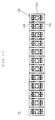
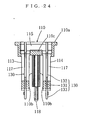
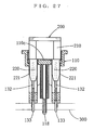
- Fig. 15 through Fig. 28 show the second example of a multiple-fuse holder H and fuse holders 100 that constitute it.
- the mini-type fuse 200 is fitted into this fuse holder 100.
- the fuse holder 100 differs from the fuse holder 100 of the first example in the following points.
- the holder housing 100 is not provided with supporting parts 116.
- the leg 133 of the contact 130 is not forked into two branches.
- the examples of the fuse holder 100, into which the mini-type fuse 200 is fitted include examples wherein the leg 133 of the contact 130 is forked into two branches.
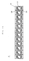
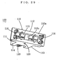
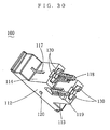
- Fig. 29 and Fig. 30 show a fuse holder which constitutes the third example multiple-fuse holder H.
- This fuse holder differs from that of the first example in the structure of the coupling part 120.
- the coupling part 120 is provided only at a point on the front wall 111 and on the rear wall 112.
- the coupling part 120 is provided at a point almost at the center of the front wall 111 and of the rear wall 112.
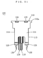
- Fig. 31 shows the fuse holder of the fourth example.
- This fuse holder differs from that of the first example in the method of fixing the contact 130 to the holder housing 110.
- the intermediate parts 131 of the contacts 130 are enveloped-cast in the holder housing 110. Enveloped-casting means that a material in a molten state sticks to the circumference of an object and solidifies over it.
- contacts 130 are set in a mold for the holder housing 110, then the material is filled into the mold to form the holder housing 110. In this way, the relative positions of the contacts 130 and the holder housing 110 will be determined with high precision.
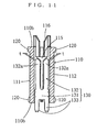
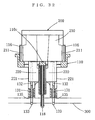
- Fig. 32 through Fig. 34 show the fuse holder of the fifth example.
- This example differs from the first example in the method of fixing the contacts 130 to the holder housing 110.
- the intermediate part 131 of the contact 130 is enveloped-cast in an insert 135, and this insert 135 is fitted into a space among the walls 111 through 114 at the bottom 110b of the holder housing 110.
- molding the holder housing 110 and enveloped-casting the insert 135 are done separately, and they can be done under optimal conditions.
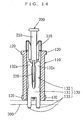
- Fig. 35 and Fig. 36 show the fuse holder of an embodiment according to the present invention. This embodiment differs from the fifth example in the configuration of the insert.
- the two inserts 135 corresponding to the respective contacts 130 are coupled by a bridge 136. With this arrangement, inserting the inserts 135 having the contact 130 into the holder housing 110 can be done by a single operation.
- the present invention does not limit the material of the insert 135.
- the insert 135 is formed of a material of which heat resistance is superior to that of the holder housing 110, the heat resistance of the holder housing 110 will not pose any problem even if the inserts 135 are subjected to heat of soldering.
- the holder housing 110 can be made of a more inexpensive material.
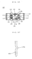
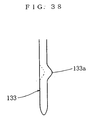
- Fig. 37 and Fig. 38 show the fuse holder of the sixth example.
- a protrusion 133a is formed in the leg 133 of the contact 130.
- This protrusion 133a is also called a clinch.
- the protrusion 133a may be formed, as shown in Fig. 37, by bending the leg 133 sidewise to form a V shape, or as shown in Fig. 38, by making a part of the leg 133 protrude sidewise.
- the present invention does not limit the color of the holder housing 110. However, if the holder housing 110 has the same color as that of the body 210 of the fuse 200, the proper fuse 200 for the fuse holder 100 can be identified easily.
- the present invention includes embodiments that combine features of the above-mentioned examples.
- the first multiple-fuse holder which was described in the summary of the invention, has been fully disclosed.
- the second multiple-fuse holder through the eleventh multiple-fuse holder which will be described below, have been fully explained.
- the second multiple-fuse holder is a multiple-fuse holder as recited in the above-mentioned first multiple-fuse holder, wherein the connecting part of the contact is formed into a fork shape, which can be expanded towards the front wall and the rear wall of the holder housing, and the clearances between the connecting part and the front wall and the rear wall are set in such a way that they allow deformation of the connecting part while limiting its excessive deformation.
- the contact has a fork shape, the production cost is lower than that of a contact having a coiled spring at the top end thereof.
- the connecting part of the contact When the connecting part of the contact is deformed, the connecting part will be prevented from excessive deformation by the front wall and the rear wall of the holder housing, thus the connecting part will be prevented from being pried by the blade terminal. Hence a high level of performance of the fuse fitting device can be guaranteed.
- the third multiple-fuse holder is a multiple-fuse holder as recited in the above-mentioned first or second multiple-fuse holder, wherein the coupling parts have a strength that can maintain the pitch between adjacent two holder housings and yet can be broken by human force.
- the coupling parts can be broken by an action such as pulling or twisting by a human hand, or the coupling parts can be broken by means of a manually operated jig such as a knife, and in turn, the multiple-fuse holder can be divided easily.
- each fuse holder can be mounted onto a printed circuit board accurately.
- the fourth multiple-fuse holder is a multiple-fuse holder as recited in any one of the above-mentioned first through third multiple-fuse holders, wherein the coupling parts are provided at a plurality of points on the wall.
- the fifth multiple-fuse holder is a multiple-fuse holder as recited in any one of the above mentioned first through third multiple-fuse holders, wherein the coupling part is provided at a single point on the wall.
- the multiple-fuse holder can be easily divided, without any use of a jig, by wrenching and breaking the coupling part.
- the sixth multiple-fuse holder is a multiple-fuse holder as recited in any one of the above-mentioned first through fifth multiple-fuse holders, wherein the holder housing group comprises twelve holder housings coupled together. With this arrangement, the multiple-fuse holder can be utilized fully, without generating any odd or waste, by dividing it when the number of fuses to be used is 12, 6, 4, 3, 2 or 1.
- the seventh multiple-fuse holder is a multiple-fuse holder as recited in any one of the above-mentioned first through sixth multiple-fuse holder, wherein the insert is formed of a material of which heat resistance is superior to that of the holder housing.
- the heat resistance of the holder housing will not pose any problem even if the insert is subjected to heat of soldering.
- the holder housing can be made of a more inexpensive material.
- the eighth multiple-fuse holder is a multiple-fuse holder as recited in any one of the above-mentioned first through seventh multiple-fuse holders, wherein the leg of the contact is forked into two branches. With this arrangement, the contact will be connected to the printed circuit board art two points, and defective connection can be prevented.
- the ninth multiple-fuse holder is a multiple-fuse holder as recited in any one of the above-mentioned first through eighth multiple-fuse holders, wherein a protrusion is formed in the leg of the contact.
- the tenth multiple-fuse holder is a multiple-fuse holder as recited in any one of the above-mentioned first through ninth multiple-fuse holders, wherein the bottom of the holder housing is provided with two bosses in positions that are asymmetric to each other in relation to a line which runs, when seen from the bottom, between the front wall and the rear wall approximately in parallel with these walls.
- the eleventh fuse holder is a multiple-fuse holder as recited in any one of the above-mentioned first through tenth multiple-fuse holders, wherein the holder housing has the same color as that of the body of the fuse. With this arrangement, the proper fuse for the fuse holder can be identified easily.
Landscapes
- Fuses (AREA)
Claims (11)
- Support multi-fusibles (H) dans lequel est insérée une pluralité de fusibles de type lame (200), avec des parties terminales en lame (220) dépassant du corps (210) de ceux-ci, ledit support multi-fusibles (H) comprenantun groupe de boîtiers supports (h) dans lequel une pluralité de boîtiers supports (110), dans chacun desquels une chambre (115) pour contenir les parties terminales en lame (220) et au moins une partie du corps (210) d'un fusible (200) insérée par le dessus, est formée avec de larges parois (111), (112) à l'avant et à l'arrière et avec des parois étroites (113), (114) sur la droite et la gauche, sont agencées à un espacement constant et chaque paire de boîtiers supports adjacents (110) sont couplées ensemble par des parties de couplage (120), dont chacune est formée intégralement sur une partie d'une paroi de ceux-ci, etdes contacts (130), à raison de deux prévus pour chaque boîtier support (110), chaque contact (130) ayant une partie intermédiaire (131) fixée au boîtier support (110), une partie de raccordement (132), à une extrémité du contact (130), s'étendant jusque dans la chambre (115) pour s'adapter à une partie terminale en lame (220), et une patte (133), à l'autre extrémité du contact (130), s'étendant hors du boîtier support (110) pour être brasée ou insérée à force sur une carte de circuit imprimé (300),dans lequel la partie intermédiaire (131) du contact (130) est coulée par coulée enveloppée dans un insert (135) et cet insert (135) est inséré dans un espace parmi les parois (111), (112), (113), (114) du boîtier support (110) et dans lequel deux des inserts (135) sont couplés ensemble.
- Support multi-fusibles (H) selon la revendication 1, dans lequel la partie de raccordement (132) du contact (130) est formée en forme de fourche, qui peut être allongée vers la paroi avant (111) et la paroi arrière (112) du boîtier support (110), etles espaces entre la partie de raccordement (132) et la paroi avant (111) et la paroi arrière (112) sont définis de telle sorte qu'ils permettent une déformation de la partie de raccordement (132) tout en limitant la déformation excessive.
- Support multi-fusibles (H) selon la revendication 1 ou 2, dans lequel les parties de couplage (120) ont une résistance qui peut maintenir l'espacement entre deux boîtiers supports adjacents (110) et peuvent pourtant être rompues par la force humaine.
- Support multi-fusibles (H) selon l'une quelconque des revendications 1 à 3, dans lequel les parties de couplage (120) sont prévues en une pluralité de points sur la paroi.
- Support multi-fusibles (H) selon l'une quelconque des revendications 1 à 3, dans lequel la partie de couplage (120) est prévue en un point unique sur la paroi.
- Support multi-fusibles (H) selon l'une quelconque des revendications précédentes, dans lequel le groupe de boîtiers support (h) comprend douze boîtiers supports (110) couplés ensemble.
- Support multi-fusibles (H) selon l'une quelconque des revendications précédentes, dans lequel l'insert (135) est formé en un matériau dont la résistance à la chaleur est supérieure à celle du boîtier support (110).
- Support multi-fusibles (H) selon l'une quelconque des revendications précédentes, dans lequel la patte (133) du contact (130) bifurque en deux branches.
- Support multi-fusibles (H) selon l'une quelconque des revendications précédentes, dans lequel une saillie (133a) est formée dans la patte (133) du contact (130).
- Support multi-fusibles (H) selon l'une quelconque des revendications précédentes, dans lequel le fond (110b) du boîtier support (110) est muni de deux bossages (118), (119) à des emplacements qui sont asymétriques l'un vis-à-vis de l'autre par rapport à une ligne qui passe, vue du dessous, entre la paroi avant (111) et la paroi arrière (112) approximativement en parallèle avec ces parois (111), (112).
- Support multi-fusibles (H) selon l'une quelconque des revendications précédentes, dans lequel le boîtier support (110) a la même couleur que celle du corps (210) du fusible (200).
Applications Claiming Priority (2)
| Application Number | Priority Date | Filing Date | Title |
|---|---|---|---|
| JP2001047355 | 2001-02-22 | ||
| JP2001047355A JP2002251953A (ja) | 2001-02-22 | 2001-02-22 | マルチヒューズホルダー |
Publications (3)
| Publication Number | Publication Date |
|---|---|
| EP1235247A2 EP1235247A2 (fr) | 2002-08-28 |
| EP1235247A3 EP1235247A3 (fr) | 2004-05-26 |
| EP1235247B1 true EP1235247B1 (fr) | 2007-06-13 |
Family
ID=18908803
Family Applications (1)
| Application Number | Title | Priority Date | Filing Date |
|---|---|---|---|
| EP02003842A Expired - Lifetime EP1235247B1 (fr) | 2001-02-22 | 2002-02-20 | Support pour plusieurs fusibles |
Country Status (5)
| Country | Link |
|---|---|
| US (1) | US6666723B2 (fr) |
| EP (1) | EP1235247B1 (fr) |
| JP (1) | JP2002251953A (fr) |
| AT (1) | ATE364893T1 (fr) |
| DE (1) | DE60220564T2 (fr) |
Families Citing this family (18)
| Publication number | Priority date | Publication date | Assignee | Title |
|---|---|---|---|---|
| JP2004186006A (ja) * | 2002-12-04 | 2004-07-02 | Yazaki Corp | ヒュージブルリンク及び該ヒュージブルリンクの製造方法 |
| US7479866B2 (en) | 2004-03-05 | 2009-01-20 | Littelfuse, Inc. | Low profile automotive fuse |
| US20050260886A1 (en) * | 2004-05-20 | 2005-11-24 | Leonard Persits | Fuse block cover |
| US20060023441A1 (en) * | 2004-08-02 | 2006-02-02 | Robert Bosch Gmbh | Modularized circuit component |
| US7564337B2 (en) * | 2005-03-03 | 2009-07-21 | Littelfuse, Inc. | Thermally decoupling fuse holder and assembly |
| JP4603415B2 (ja) * | 2005-05-12 | 2010-12-22 | 太平洋精工株式会社 | ヒューズ |
| USD559203S1 (en) | 2006-11-14 | 2008-01-08 | Littelfuse, Inc. | Indicator for a fuse |
| JP2009153239A (ja) * | 2007-12-18 | 2009-07-09 | Sumitomo Wiring Syst Ltd | 電気接続箱 |
| US8077007B2 (en) | 2008-01-14 | 2011-12-13 | Littlelfuse, Inc. | Blade fuse |
| USD575746S1 (en) | 2008-01-14 | 2008-08-26 | Littelfuse, Inc. | Blade fuse and fuse element therefore |
| USD575745S1 (en) | 2008-01-14 | 2008-08-26 | Littelfuse, Inc. | Blade fuse and fuse element therefore |
| JP5141917B2 (ja) * | 2009-06-25 | 2013-02-13 | 住友電装株式会社 | 実装基板 |
| US8105113B2 (en) * | 2010-04-21 | 2012-01-31 | Delphi Technologies, Inc. | Fuse adapter |
| EP2759024A1 (fr) * | 2011-09-20 | 2014-07-30 | ERNI Production GmbH & Co. KG. | Élément à enfichage |
| JP5838955B2 (ja) * | 2012-11-26 | 2016-01-06 | アンデン株式会社 | ヒューズ装着構造 |
| CN106710996B (zh) * | 2016-12-07 | 2019-03-01 | 宁波爱维斯工贸有限公司 | 扩展式多用途保险座 |
| US10636606B1 (en) * | 2019-03-01 | 2020-04-28 | Sumitomo Wiring Systems, Ltd. | Fuse housing assembly |
| JP1750364S (ja) * | 2022-09-12 | 2023-08-07 | ヒューズ |
Family Cites Families (35)
| Publication number | Priority date | Publication date | Assignee | Title |
|---|---|---|---|---|
| US1952554A (en) * | 1930-09-04 | 1934-03-27 | Railroad Accessories Corp | Terminal block |
| US3046516A (en) * | 1957-12-16 | 1962-07-24 | Tymkewicz John | Panel-mounted electrical connector |
| US3182276A (en) * | 1962-02-26 | 1965-05-04 | Elco Corp | Contact assembly with thermoplastic backing strip |
| US3378808A (en) | 1967-01-09 | 1968-04-16 | Army Usa | Electrical connector for terminating flat wire cables |
| US3848951A (en) | 1973-01-12 | 1974-11-19 | Molex Inc | Connector housings and locking structures therefor |
| DE2511459A1 (de) * | 1975-03-15 | 1976-09-23 | Rau Swf Autozubehoer | Anordnung zur absicherung der elektrischen anlage eines motorgetriebenen fahrzeuges |
| US4094564A (en) * | 1977-03-17 | 1978-06-13 | A P Products Incorporated | Multiple conductor electrical connector with ground bus |
| CH628484A5 (de) | 1978-04-21 | 1982-02-26 | Erni & Co Elektro Ind | Verfahren und kontaktleiste zur herstellung gasdichter verbindungen fuer eine gedruckte rueckwandverdrahtung. |
| US4184733A (en) | 1978-07-24 | 1980-01-22 | Square D Company | Segmented fanning strip |
| US4230387A (en) * | 1979-04-18 | 1980-10-28 | General Staple Company, Inc. | Continuous connector |
| IT1155643B (it) * | 1982-03-17 | 1987-01-28 | Fiat Auto Spa | Blocchetto portafusibile singolo componibile per portafusibili lamellari |
| US4560227A (en) * | 1983-02-04 | 1985-12-24 | Littelfuse, Inc. | Fuseholder for blade-type fuses |
| DE8535226U1 (de) * | 1985-12-14 | 1986-02-06 | Bremi Auto-Elektrik Bremicker GmbH + Co, 5883 Kierspe | Fassung für elektrische Flachstecker-Schmelzsicherungen für Kfz |
| US4944684A (en) * | 1988-06-28 | 1990-07-31 | Trw, Inc. | Electrical junction box and method for its manufacture |
| US4943248A (en) | 1988-06-29 | 1990-07-24 | Molex Incorporated | Electrical terminal for bladed fuse |
| EP0349154A3 (fr) * | 1988-06-29 | 1990-10-03 | Molex Incorporated | Borne électrique et connecteur pour fusible à lames |
| US5194018A (en) * | 1992-01-22 | 1993-03-16 | Molex Incorporated | Electrical connector assembly and method of fabricating same |
| JPH05342979A (ja) | 1992-06-08 | 1993-12-24 | Yazaki Corp | 暗電流用ヒューズ機構 |
| JPH06150806A (ja) | 1992-11-13 | 1994-05-31 | Yazaki Corp | ヒューズブロックにおけるミニヒューズ保持構造 |
| US5281171A (en) * | 1992-12-17 | 1994-01-25 | Carrier Corporation | Fuse holding device |
| JPH06231672A (ja) | 1993-02-08 | 1994-08-19 | Yazaki Corp | ヒューズホルダ |
| US5424896A (en) | 1993-08-12 | 1995-06-13 | Lsi Logic Corporation | Semiconductor package electrostatic discharge damage protection |
| JP3404832B2 (ja) * | 1993-10-15 | 2003-05-12 | 住友電装株式会社 | コネクタの製造方法及びコネクタ |
| US5409399A (en) | 1993-12-08 | 1995-04-25 | Molex Incorporated | Electrical connection assembly for mounting on a printed circuit board |
| JP3083061B2 (ja) | 1995-01-20 | 2000-09-04 | 矢崎総業株式会社 | ヒューズ接続構造 |
| JP3403570B2 (ja) | 1996-03-07 | 2003-05-06 | 矢崎総業株式会社 | ヒューズホルダ |
| US5785537A (en) | 1996-06-26 | 1998-07-28 | Robinson Nugent, Inc. | Electrical connector interlocking apparatus |
| US5752856A (en) * | 1996-07-30 | 1998-05-19 | The Whitaker Corporation | Sealed fuse connector |
| JP3685908B2 (ja) | 1997-05-30 | 2005-08-24 | 富士通コンポーネント株式会社 | 高速伝送用コネクタ |
| US6089918A (en) | 1997-06-30 | 2000-07-18 | Yazaki Corporation | Adapter for electrical circuit components |
| US6155860A (en) | 1998-01-31 | 2000-12-05 | Berg Technology, Inc. | Socket for electrical component |
| US6280253B1 (en) | 1999-04-22 | 2001-08-28 | Visteon Global Technologies, Inc. | Method and apparatus for selectively connecting electrical circuits and components |
| FR2798778B1 (fr) * | 1999-09-17 | 2002-08-23 | Proner Comatel Sa | Procede de fabrication en serie de modules porte-fusible et modules porte-fusible obtenus par le procede |
| USD462061S1 (en) | 2000-12-21 | 2002-08-27 | J.S.T. Mfg. Co., Ltd. | Fuse holder |
| US20040265235A1 (en) | 2003-06-26 | 2004-12-30 | Uzgiris Egidijus Edward | Magnetic resonance contrast-enhancing agents and method for detecting and imaging artherosclerotic plaque |
-
2001
- 2001-02-22 JP JP2001047355A patent/JP2002251953A/ja active Pending
-
2002
- 2002-02-19 US US10/080,154 patent/US6666723B2/en not_active Expired - Fee Related
- 2002-02-20 EP EP02003842A patent/EP1235247B1/fr not_active Expired - Lifetime
- 2002-02-20 DE DE60220564T patent/DE60220564T2/de not_active Expired - Lifetime
- 2002-02-20 AT AT02003842T patent/ATE364893T1/de not_active IP Right Cessation
Also Published As
| Publication number | Publication date |
|---|---|
| EP1235247A3 (fr) | 2004-05-26 |
| DE60220564T2 (de) | 2007-09-27 |
| US20020115349A1 (en) | 2002-08-22 |
| US6666723B2 (en) | 2003-12-23 |
| DE60220564D1 (de) | 2007-07-26 |
| ATE364893T1 (de) | 2007-07-15 |
| JP2002251953A (ja) | 2002-09-06 |
| EP1235247A2 (fr) | 2002-08-28 |
Similar Documents
| Publication | Publication Date | Title |
|---|---|---|
| EP1235247B1 (fr) | Support pour plusieurs fusibles | |
| EP1235246B1 (fr) | Porte-fusible | |
| EP1235245B1 (fr) | Porte-fusible | |
| EP1213741B1 (fr) | Boîte à fusibles | |
| US6780026B2 (en) | Electrical junction box | |
| US20060119463A1 (en) | Fuse cavity structure and electric connection box | |
| JP2007527602A (ja) | 薄型の自動車用ヒューズ | |
| US7232342B2 (en) | Fuse cavity and electric junction box equipped therewith | |
| US7414194B2 (en) | Bus bar wiring board and method of assembling the same | |
| GB2093641A (en) | Improvements in or relating to electrical contacts | |
| JP4096800B2 (ja) | 自動車用リレーボックス | |
| JP4361474B2 (ja) | 電気回路ユニットと電気接続箱との着脱方法および着脱構造 | |
| JP3994908B2 (ja) | 自動車用電気接続箱 | |
| EP1094569B1 (fr) | Contact de connexion et connecteur comprenant ce contact | |
| KR101531315B1 (ko) | 퓨즈 및 퓨즈 장착 구조 | |
| JP4593164B2 (ja) | マルチヒューズホルダー | |
| EP1548787B1 (fr) | Structure de barre omnibus, boîte de connexion électrique avec une telle structure et procédé de formation de barre omnibus | |
| JP6201811B2 (ja) | 電磁継電器 | |
| JPH0773938A (ja) | ジョイントコネクタおよびジョイント端子 | |
| JPH0822762A (ja) | ヒューズの二次ショート防止構造 | |
| JP2023177073A (ja) | ジョイントバスバー | |
| EP1548786B1 (fr) | Ensemble de bornes de connexion de fusible pour barre omnibus et boîtier de connexion électrique avec un tel ensemble | |
| JP2004228097A5 (fr) | ||
| JP2003037918A (ja) | ヒューズ部を設けたバスバー、該バスバーの形成方法および該バスバーを備えた自動車用リレーボックス | |
| JP2003070131A (ja) | ジャンクションボックスおよび該ジャンクションボックスのケース成形方法 |
Legal Events
| Date | Code | Title | Description |
|---|---|---|---|
| PUAI | Public reference made under article 153(3) epc to a published international application that has entered the european phase |
Free format text: ORIGINAL CODE: 0009012 |
|
| AK | Designated contracting states |
Kind code of ref document: A2 Designated state(s): AT BE CH CY DE DK ES FI FR GB GR IE IT LI LU MC NL PT SE TR |
|
| AX | Request for extension of the european patent |
Free format text: AL;LT;LV;MK;RO;SI |
|
| PUAL | Search report despatched |
Free format text: ORIGINAL CODE: 0009013 |
|
| AK | Designated contracting states |
Kind code of ref document: A3 Designated state(s): AT BE CH CY DE DK ES FI FR GB GR IE IT LI LU MC NL PT SE TR |
|
| AX | Request for extension of the european patent |
Extension state: AL LT LV MK RO SI |
|
| 17P | Request for examination filed |
Effective date: 20040907 |
|
| AKX | Designation fees paid |
Designated state(s): AT BE CH CY DE DK ES FI FR GB GR IE IT LI LU MC NL PT SE TR |
|
| 17Q | First examination report despatched |
Effective date: 20060324 |
|
| GRAP | Despatch of communication of intention to grant a patent |
Free format text: ORIGINAL CODE: EPIDOSNIGR1 |
|
| GRAS | Grant fee paid |
Free format text: ORIGINAL CODE: EPIDOSNIGR3 |
|
| GRAL | Information related to payment of fee for publishing/printing deleted |
Free format text: ORIGINAL CODE: EPIDOSDIGR3 |
|
| GRAS | Grant fee paid |
Free format text: ORIGINAL CODE: EPIDOSNIGR3 |
|
| GRAA | (expected) grant |
Free format text: ORIGINAL CODE: 0009210 |
|
| AK | Designated contracting states |
Kind code of ref document: B1 Designated state(s): AT BE CH CY DE DK ES FI FR GB GR IE IT LI LU MC NL PT SE TR |
|
| PG25 | Lapsed in a contracting state [announced via postgrant information from national office to epo] |
Ref country code: CH Free format text: LAPSE BECAUSE OF FAILURE TO SUBMIT A TRANSLATION OF THE DESCRIPTION OR TO PAY THE FEE WITHIN THE PRESCRIBED TIME-LIMIT Effective date: 20070613 Ref country code: LI Free format text: LAPSE BECAUSE OF FAILURE TO SUBMIT A TRANSLATION OF THE DESCRIPTION OR TO PAY THE FEE WITHIN THE PRESCRIBED TIME-LIMIT Effective date: 20070613 |
|
| REG | Reference to a national code |
Ref country code: GB Ref legal event code: FG4D |
|
| REG | Reference to a national code |
Ref country code: CH Ref legal event code: EP |
|
| REG | Reference to a national code |
Ref country code: IE Ref legal event code: FG4D |
|
| REF | Corresponds to: |
Ref document number: 60220564 Country of ref document: DE Date of ref document: 20070726 Kind code of ref document: P |
|
| PG25 | Lapsed in a contracting state [announced via postgrant information from national office to epo] |
Ref country code: SE Free format text: LAPSE BECAUSE OF FAILURE TO SUBMIT A TRANSLATION OF THE DESCRIPTION OR TO PAY THE FEE WITHIN THE PRESCRIBED TIME-LIMIT Effective date: 20070913 |
|
| PG25 | Lapsed in a contracting state [announced via postgrant information from national office to epo] |
Ref country code: AT Free format text: LAPSE BECAUSE OF FAILURE TO SUBMIT A TRANSLATION OF THE DESCRIPTION OR TO PAY THE FEE WITHIN THE PRESCRIBED TIME-LIMIT Effective date: 20070613 |
|
| NLV1 | Nl: lapsed or annulled due to failure to fulfill the requirements of art. 29p and 29m of the patents act | ||
| REG | Reference to a national code |
Ref country code: CH Ref legal event code: PL |
|
| PG25 | Lapsed in a contracting state [announced via postgrant information from national office to epo] |
Ref country code: BE Free format text: LAPSE BECAUSE OF FAILURE TO SUBMIT A TRANSLATION OF THE DESCRIPTION OR TO PAY THE FEE WITHIN THE PRESCRIBED TIME-LIMIT Effective date: 20070613 |
|
| PG25 | Lapsed in a contracting state [announced via postgrant information from national office to epo] |
Ref country code: NL Free format text: LAPSE BECAUSE OF FAILURE TO SUBMIT A TRANSLATION OF THE DESCRIPTION OR TO PAY THE FEE WITHIN THE PRESCRIBED TIME-LIMIT Effective date: 20070613 Ref country code: ES Free format text: LAPSE BECAUSE OF FAILURE TO SUBMIT A TRANSLATION OF THE DESCRIPTION OR TO PAY THE FEE WITHIN THE PRESCRIBED TIME-LIMIT Effective date: 20070924 Ref country code: PT Free format text: LAPSE BECAUSE OF FAILURE TO SUBMIT A TRANSLATION OF THE DESCRIPTION OR TO PAY THE FEE WITHIN THE PRESCRIBED TIME-LIMIT Effective date: 20071113 |
|
| PLBE | No opposition filed within time limit |
Free format text: ORIGINAL CODE: 0009261 |
|
| STAA | Information on the status of an ep patent application or granted ep patent |
Free format text: STATUS: NO OPPOSITION FILED WITHIN TIME LIMIT |
|
| PG25 | Lapsed in a contracting state [announced via postgrant information from national office to epo] |
Ref country code: IT Free format text: LAPSE BECAUSE OF FAILURE TO SUBMIT A TRANSLATION OF THE DESCRIPTION OR TO PAY THE FEE WITHIN THE PRESCRIBED TIME-LIMIT Effective date: 20070613 Ref country code: DK Free format text: LAPSE BECAUSE OF FAILURE TO SUBMIT A TRANSLATION OF THE DESCRIPTION OR TO PAY THE FEE WITHIN THE PRESCRIBED TIME-LIMIT Effective date: 20070613 Ref country code: GR Free format text: LAPSE BECAUSE OF FAILURE TO SUBMIT A TRANSLATION OF THE DESCRIPTION OR TO PAY THE FEE WITHIN THE PRESCRIBED TIME-LIMIT Effective date: 20070914 |
|
| 26N | No opposition filed |
Effective date: 20080314 |
|
| PG25 | Lapsed in a contracting state [announced via postgrant information from national office to epo] |
Ref country code: MC Free format text: LAPSE BECAUSE OF NON-PAYMENT OF DUE FEES Effective date: 20080228 |
|
| PG25 | Lapsed in a contracting state [announced via postgrant information from national office to epo] |
Ref country code: IE Free format text: LAPSE BECAUSE OF NON-PAYMENT OF DUE FEES Effective date: 20080220 |
|
| PG25 | Lapsed in a contracting state [announced via postgrant information from national office to epo] |
Ref country code: FI Free format text: LAPSE BECAUSE OF FAILURE TO SUBMIT A TRANSLATION OF THE DESCRIPTION OR TO PAY THE FEE WITHIN THE PRESCRIBED TIME-LIMIT Effective date: 20070613 |
|
| PG25 | Lapsed in a contracting state [announced via postgrant information from national office to epo] |
Ref country code: CY Free format text: LAPSE BECAUSE OF FAILURE TO SUBMIT A TRANSLATION OF THE DESCRIPTION OR TO PAY THE FEE WITHIN THE PRESCRIBED TIME-LIMIT Effective date: 20070613 |
|
| PG25 | Lapsed in a contracting state [announced via postgrant information from national office to epo] |
Ref country code: LU Free format text: LAPSE BECAUSE OF NON-PAYMENT OF DUE FEES Effective date: 20080220 |
|
| PG25 | Lapsed in a contracting state [announced via postgrant information from national office to epo] |
Ref country code: TR Free format text: LAPSE BECAUSE OF FAILURE TO SUBMIT A TRANSLATION OF THE DESCRIPTION OR TO PAY THE FEE WITHIN THE PRESCRIBED TIME-LIMIT Effective date: 20070613 |
|
| PGFP | Annual fee paid to national office [announced via postgrant information from national office to epo] |
Ref country code: FR Payment date: 20110301 Year of fee payment: 10 Ref country code: DE Payment date: 20110224 Year of fee payment: 10 |
|
| PGFP | Annual fee paid to national office [announced via postgrant information from national office to epo] |
Ref country code: GB Payment date: 20110221 Year of fee payment: 10 |
|
| GBPC | Gb: european patent ceased through non-payment of renewal fee |
Effective date: 20120220 |
|
| REG | Reference to a national code |
Ref country code: FR Ref legal event code: ST Effective date: 20121031 |
|
| REG | Reference to a national code |
Ref country code: DE Ref legal event code: R119 Ref document number: 60220564 Country of ref document: DE Effective date: 20120901 |
|
| PG25 | Lapsed in a contracting state [announced via postgrant information from national office to epo] |
Ref country code: GB Free format text: LAPSE BECAUSE OF NON-PAYMENT OF DUE FEES Effective date: 20120220 Ref country code: FR Free format text: LAPSE BECAUSE OF NON-PAYMENT OF DUE FEES Effective date: 20120229 |
|
| PG25 | Lapsed in a contracting state [announced via postgrant information from national office to epo] |
Ref country code: DE Free format text: LAPSE BECAUSE OF NON-PAYMENT OF DUE FEES Effective date: 20120901 |