EP1236214B1 - Vakuumschütz mit verschiebbarem führungselement - Google Patents
Vakuumschütz mit verschiebbarem führungselement Download PDFInfo
- Publication number
- EP1236214B1 EP1236214B1 EP00984906A EP00984906A EP1236214B1 EP 1236214 B1 EP1236214 B1 EP 1236214B1 EP 00984906 A EP00984906 A EP 00984906A EP 00984906 A EP00984906 A EP 00984906A EP 1236214 B1 EP1236214 B1 EP 1236214B1
- Authority
- EP
- European Patent Office
- Prior art keywords
- vacuum contactor
- guide
- contactor according
- enclosure
- guide element
- Prior art date
- Legal status (The legal status is an assumption and is not a legal conclusion. Google has not performed a legal analysis and makes no representation as to the accuracy of the status listed.)
- Expired - Lifetime
Links
- 230000006835 compression Effects 0.000 claims description 6
- 238000007906 compression Methods 0.000 claims description 6
- 230000003993 interaction Effects 0.000 claims description 2
- 239000006223 plastic coating Substances 0.000 claims 1
- 238000006073 displacement reaction Methods 0.000 description 4
- 230000004913 activation Effects 0.000 description 1
- 238000010276 construction Methods 0.000 description 1
- 230000001419 dependent effect Effects 0.000 description 1
- 230000009977 dual effect Effects 0.000 description 1
- 238000004519 manufacturing process Methods 0.000 description 1
- 238000007493 shaping process Methods 0.000 description 1
Images

Classifications
-
- H—ELECTRICITY
- H01—ELECTRIC ELEMENTS
- H01H—ELECTRIC SWITCHES; RELAYS; SELECTORS; EMERGENCY PROTECTIVE DEVICES
- H01H33/00—High-tension or heavy-current switches with arc-extinguishing or arc-preventing means
- H01H33/60—Switches wherein the means for extinguishing or preventing the arc do not include separate means for obtaining or increasing flow of arc-extinguishing fluid
- H01H33/66—Vacuum switches
- H01H33/666—Operating arrangements
-
- H—ELECTRICITY
- H01—ELECTRIC ELEMENTS
- H01H—ELECTRIC SWITCHES; RELAYS; SELECTORS; EMERGENCY PROTECTIVE DEVICES
- H01H33/00—High-tension or heavy-current switches with arc-extinguishing or arc-preventing means
- H01H33/60—Switches wherein the means for extinguishing or preventing the arc do not include separate means for obtaining or increasing flow of arc-extinguishing fluid
- H01H33/66—Vacuum switches
- H01H33/662—Housings or protective screens
- H01H33/66238—Specific bellows details
- H01H2033/66246—Details relating to the guiding of the contact rod in vacuum switch belows
-
- H—ELECTRICITY
- H01—ELECTRIC ELEMENTS
- H01H—ELECTRIC SWITCHES; RELAYS; SELECTORS; EMERGENCY PROTECTIVE DEVICES
- H01H33/00—High-tension or heavy-current switches with arc-extinguishing or arc-preventing means
- H01H33/60—Switches wherein the means for extinguishing or preventing the arc do not include separate means for obtaining or increasing flow of arc-extinguishing fluid
- H01H33/66—Vacuum switches
- H01H33/662—Housings or protective screens
- H01H33/66238—Specific bellows details
- H01H2033/66253—Details relating to the prevention of unwanted rotation of the contact rod in vacuum switch bellows
Definitions
- the invention relates to a trained as a vacuum contactor switching device with a housing-fixed contact (fixed contact) and a displaceable for producing a current-conducting connection contact (floating bearing) with the other features of the preamble of claim 1.
- vacuum contactors are known in which a sleeve is mounted on the floating bearing, which slides on a pin fixed to the housing. Furthermore, vacuum contactors are known in which a guide ring is provided on the vacuum tube.
- the tube stud producing the contact slides into this ring.
- the guide ring can be arranged on the fixed or floating bearing side.
- EP 0 641 001 A1 discloses a switch with a vacuum interrupter, in which a contact carrier, movable by a drive, of a moving contact piece is vacuum-tight by means of a bellows and held on a tube axis by means of a sliding guide and guided out of the housing of the switch.
- the switch described has a guide groove 22 which is received in a one-piece socket 12, which in turn merges into a mounting flange 13. This is fastened by screw 15 to a flange 16 of the housing 7 of the switch. To remove the movable contact carrier 8 of the switch, the screw 15 are to be solved and the mounting flange 13 must be removed from the housing 7.
- the invention has for its object to offer a vacuum contactor with a more user-friendly floating bearing.
- the task is characterized by the characteristics of the characteristic Part of claim 1 in conjunction with the features of the preamble.
- Advantageous embodiments are described in the dependent claims 2-10.
- Contactors are switching devices and are used e.g. used for switching motors.
- the contactors can be designed as air guns or as vacuum contactors.
- the vacuum switching device according to the invention - short vacuum contactor - for opening and closing of circuits has a movable bearing with at least one guided in a groove (recess) of the housing of the vacuum contactor and displaced upon actuation of the movable bearing guide element.
- the guide element may be attached to a spring support of a compression spring for generating additional justifyanpreßdrucks of the movable bearing on the fixed contact, whereby the spring support has a dual function.
- the guide element is attached to a ring element arranged adjacent to the bellows element and thus close to the contact point of the movable bearing, a particularly secure floating bearing guide is achieved.
- a simplified structural design of the vacuum contactor is achieved when the ring element next to attached guide element still has an indicator for indicating the displacement position of the movable bearing (closed / open) and / or a projection for positioning an angle element for attaching a current band on the floating bearing.
- Essentially cuboid-shaped guide elements can be produced inexpensively. Basically, the geometry of the guide element and the corresponding groove. (Guide groove) matched to form a positive fit and can be adapted in its cross section to the respective required load profile and, for. also be triangular or semicircular.
- groove is to be understood as a recess of any kind.
- the grooves or grooves for receiving the guide element or the guide elements can be used as e.g. milled recesses or depressions produced in the housing of the vacuum contactor produced in any other way by primary shaping, material-removing or material-compacting production methods.
- the groove for receiving the guide element is formed by the interaction of the (applied) cover of the housing with the lower part of the housing, so that when the housing is open and removed cover the movable bearing easy to use, for. for repair or replacement of the vacuum tube from the housing (from above) can be removed.
- the individual phases are switched on and off separately and are located the assigned associated vacuum tubes usually in housings with adjacently arranged housing chambers for receiving the individual vacuum tubes.
- FIG. 1 a single tube assembly according to FIG. 1 is accommodated in each housing chamber.
- the tube assembly of FIG 1 has a fixed bearing 33 with attached fixed contact 1 of FIG. 2
- the tube 15 is mounted, in which the bolt 16 of the movable bearing 2 (see FIG 2) is located.
- the bolt 16 of the movable bearing 2 see FIG 2
- the tube 15 with bellows 3 follow the ring member 9 with indicator 10, the angle member 28 and the compression spring 8, which is received in the spring support 7.
- the lever 23 engages according to FIG 2 (not shown in FIG 1).
- the floating bearing 2 Upon activation of the vacuum contactor of Figure 1, the floating bearing 2 is displaced in the tube 15 with compression of the bellows member 3 and the compression spring 8, whereby the guide elements 6a, 6b and 6c in the respective corresponding grooves 5a and 5b (longitudinal grooves) of the adjacent housing walls 31 and 32 are moved and guided (see FIG 2 and FIG 3).
- Guide element 6d is located opposite guide element 6a (see FIG. 3) and can not be seen in FIG.
- the fixed bearing 33 of the vacuum contactor is shown in FIG 2, the fixed contact 1, which is conductively connected via the fixed bearing member 18 to the terminal rail 19 for power input.
- the sleeve 22 and the angle member 28 are mounted on the bolt 16.
- lever 23 of the lever member 29 which is rotatably received on the bearing member 24 and 25 causes a closure of the vacuum contactor by displacement of the bolt 16 of the movable bearing 2 for fixed contact 1 upon actuation of the contact carrier 25.
- the angle element 28 is connected via the current band 14 to the connecting rail 27.
- the vacuum contactor When the vacuum contactor is closed, there is a current connection between the connecting rail 19 and the connecting rail 27 via the fixed contact 1 and the floating bearing 2.
- the leadership of the floating bearing 2 is achieved by the guide elements 6a to 6d, which are formed substantially cuboid.
- the guide elements 6a and 6d are mounted on a ring element 9 surrounding the pin 16, which a projection 34 which serves to position the angle member 28 and the compression spring 8.
- the guide elements 6b and 6c are located on the spring support. 7
- the tube assembly is shown in FIG 2 in a housing 4 with removable cover 11.
- the lid 11 has a recess 30 through which the indicator 10 of the ring member 9 is visible.
- the displacement of the indicator 10 upon displacement of the movable bearing 2 can be seen, so that the operator can recognize the switching state of the vacuum contactor (open / closed) when the housing 4 is closed with the lid 11 on the position of the indicator 10 in the recess 30.
- the guide elements 6a and 6d of the ring element 9 are guided in the grooves 5a and 5b, which are formed by cooperation of the recesses 12a and 12b of the housing walls 31 and 32 with the contact surfaces 13a and 13b of the lid 11 with the cover 11 applied. This ensures that the movable bearing 2 with the cover removed 11 easy to use, for. is accessible for exchange.
- the grooves 5a and 5b can also be formed by recesses which are completely in the housing walls 31 and 32 or a recess on the lid 11, which cooperates with a contact surface in the housing 4 (not shown).
- the guide elements 6b and 6c are guided in the associated grooves 5 (or groove areas) with greater play than the guide elements 6a and 6d in their associated grooves 5 (or groove areas), in order to cause a slight tilting movement of the bolt 16 during closing and opening of the housing Loslagers 2 because of the rotational movement of the lever 23 to allow the bearing element 24 (not shown).
Landscapes
- High-Tension Arc-Extinguishing Switches Without Spraying Means (AREA)
- Magnetic Bearings And Hydrostatic Bearings (AREA)
Abstract
Description
- Die Erfindung betrifft ein als Vakuumschütz ausgebildetes Schaltgerät mit einem gehäusefesten Kontakt (Festkontakt) und einem zur Herstellung einer stromleitenden Verbindung verschiebbaren Kontakt (Loslager) mit den weiteren Merkmalen des Oberbegriffs des Patentanspruchs 1.
- Als Stand der Technik sind Vakuumschütze bekannt, bei denen am Loslager eine Hülse angebracht ist, die auf einem gehäusefesten Zapfen abgleitet. Ferner sind Vakuumschütze bekannt, bei denen an der Vakuumröhre ein Führungsring vorgesehen ist.
- Bei diesem Aufbau gleitet der den Kontakt herstellende Röhrenbolzen in diesen Ring. Der Führungsring kann dabei auf der Fest- oder Loslagerseite angeordnet sein.
- Aus der EP 0 641 001 Al geht ein Schalter mit einer Vakuumschaltröhre hervor, bei dem ein von einem Antrieb bewegbarer Kontaktträger eines beweglichen Schaltstücks mittels eines Faltenbalgs vakuumdicht und mittels einer Gleitführung auf einer Röhrenachse gehalten und aus dem Gehäuse des Schalters geführt wird.
- Der beschriebene Schalter besitzt eine Führungsnut 22, welche in einer einteiligen Buchse 12 aufgenommen ist, die wiederum in ein Montageflansch 13 übergeht. Dieser ist durch Schraubverbindungen 15 an einem Flansch 16 des Gehäuses 7 des Schalters befestigt. Zur Entnahme des beweglichen Kontaktträgers 8 des Schalters sind die Schraubverbindungen 15 zu lösen und der Montageflansch 13 muß vom Gehäuse 7 abgezogen werden.
- Der Erfindung liegt die Aufgabe zugrunde, ein Vakuumschütz mit einer bedienungsfreundlicheren Loslagerführung anzubieten. Die Aufgabe wird durch die Merkmale des kennzeichnenden Teils des Patentanspruchs 1 in Verbindung mit den Merkmalen des Oberbegriffs gelöst. Vorteilhafte Ausführungsformen werden in den Unteransprüchen 2 - 10 beschrieben.
- Schütze sind Schaltgeräte und werden z.B. zum Schalten von Motoren verwendet. Die Schütze können als Luftschütze oder als Vakuumschütze ausgebildet sein.
- Das erfindungsgemäße Vakuumschaltgerät - kurz Vakuumschütz - zum Öffnen und Schließen von Stromkreisen besitzt ein Loslager mit mindestens einem in einer Nut (Ausnehmung) des Gehäuses des Vakuumschützes geführten und bei Betätigung des Loslagers verschobenen Führungselement. Hierdurch wird das Loslager störungssicher mit hoher Wiederholgenauigkeit im Gehäuse aufgenommen und geführt.
- Dabei kann das Führungselement an einer Federauflage einer Druckfeder zur Erzeugung zusätzlichen Kontaktanpreßdrucks des Loslagers am Festkontakt angebracht sein, wodurch die Federauflage eine Doppelfunktion besitzt.
- Wenn das Führungselement an einem benachbart zum Balgelement angeordneten Ringelement und damit nahe der Kontaktstelle des Loslagers angebracht ist, wird eine besonders sichere Loslagerführung erreicht.
- Zur weiteren Verbesserung der Führungseigenschaften des Loslagers können auch mehrere z.B. gegenüberliegende Führungselemente an der Federauflage und/oder an einem Ringelement vorgesehen sein.
- Ein vereinfachter konstruktiver Aufbau des Vakuumschützes wird erzielt, wenn das Ringelement neben angebrachtem Führungselement noch einen Indikator zur Anzeige der Verschiebeposition des Loslagers (geschlossen/geöffnet) und/oder einen Vorsprung zur Positionierung eines Winkelelementes zur Anbringung eines Strombandes am Loslager besitzt.
- Im wesentlichen quaderförmig ausgebildete Führungselemente können kostengünstig hergestellt werden. Grundsätzlich sind die Geometrie des Führungselements und der korrespondierenden Nut. (Führungsnut) zur Herstellung eines Formschlusses aufeinander abgestimmt und können in ihrem Querschnitt an das jeweilige erforderliche Belastungsprofil angepaßt werden und z.B. auch dreieckförmig oder halbkreisförmig ausgebildet sein.
- Dabei ist der Begriff Nut als Ausnehmung jeglicher Art aufzufassen. Die Nut bzw. Nuten zur Aufnahme des Führungselements bzw. der Führungselemente können als z.B. eingefräste oder auf sonstige Weise durch urformende, materialabtragende oder materialverdichtende Fertigungsverfahren erzeugte Ausnehmungen/Vertiefungen im Gehäuse des Vakuumschützes hergestellt werden.
- Erfindungsgemäß wird die Nut zur Aufnahme des Führungselementes durch Zusammenwirken des (aufgelegten) Deckels des Gehäuses mit dem Unterteil des Gehäuses gebildet, so daß bei geöffnetem Gehäuse und abgenommenem Deckel das Loslager bedienungsfreundlich z.B. zur Reparatur oder zum Austausch der Vakuumröhre aus dem Gehäuse (von oben) entnehmbar ist.
- Weitere Einzelheiten der Erfindung gehen aus den Ausführungsbeispielen in den Zeichnungsfiguren hervor. Es zeigen:
- FIG 1
- eine perspektivische Gesamtansicht eines Vakuumschützes (Röhrenbaugruppe, Strombahn) ohne Gehäuse,
- FIG 2
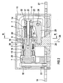
- ein Längsschnitt durch den Vakuumschütz nach FIG 1 mit umgebendem Gehäuse sowie
- FIG 3
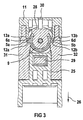
- ein Schnitt B-B nach FIG 2.
- Bei Ansteuerung von dreiphasigen Drehstrommotoren werden die einzelnen Phasen separat zu- und abgeschaltet und befinden sich die hierzu verwendeten zugeordneten Vakuumröhren üblicherweise in Gehäusen mit benachbart angeordneten Gehäusekammern zur Aufnahme der einzelnen Vakuumröhren.
- Dabei ist in jeder Gehäusekammer eine einzelne Röhrenbaugruppe nach FIG 1 aufgenommen. Die Röhrenbaugruppe nach FIG 1 besitzt ein Festlager 33 mit angebautem Festkontakt 1 nach FIG 2.
- Am Festlager 33 ist die Röhre 15 angebracht, in der sich der Bolzen 16 des Loslagers 2 (vgl. FIG 2) befindet. Auf die Röhre 15 mit Balgelement 3 folgen das Ringelement 9 mit Indikator 10, das Winkelelement 28 und die Druckfeder 8, welche in der Federauflage 7 aufgenommen ist. Zwischen Federauflage 7 und Hebelauflage 17 greift der Hebel 23 nach FIG 2 ein (in FIG 1 nicht dargestellt).
- Bei Aktivierung des Vakuumschützes nach FIG 1 wird das Loslager 2 in der Röhre 15 unter Komprimierung des Balgelements 3 und der Druckfeder 8 verschoben, wodurch die Führungselemente 6a, 6b und 6c in den jeweiligen korrespondierenden Nuten 5a und 5b (Längsnuten) der benachbarten Gehäusewände 31 und 32 verschoben und geführt werden (vgl. FIG 2 und FIG 3). Führungselement 6d befindet sich gegenüber von Führungselement 6a (vgl. FIG 3) und ist in FIG 1 nicht einsehbar.
- Am Festlager 33 des Vakuumschützes befindet sich nach FIG 2 der Festkontakt 1, welcher leitend über das Festlagerelement 18 mit der Anschlußschiene 19 zur Stromeinleitung verbunden ist.
- FIG 2 zeigt den Vakuumschütz in geöffneter Schaltstellung, wobei der Bolzen 16 des Loslagers 2 in der Röhre 15 und im Balgelement 3 an der Kontaktstelle 20 beabstandet zum Festkontakt 1 angeordnet ist.
- Über die Befestigungsschraube 21 sind die Hülse 22 und das Winkelelement 28 am Bolzen 16 angebracht. Zwischen Hebelauflage 17 und Federauflage 7 befindet sich der Hebel 23 des Hebelelements 29, welches drehbar am das Lagerelement 24 aufgenommen ist und bei Betätigung des Kontaktträgers 25 in Verschieberichtung 26 eine Schließung des Vakuumschützes durch eine Verschiebung des Bolzens 16 des Loslagers 2 zum Festkontakt 1 bewirkt.
- Das Winkelelement 28 ist über das Stromband 14 mit der Anschlußschiene 27 verbunden. Bei geschlossenem Vakuumschütz besteht eine Stromverbindung zwischen Anschlußschiene 19 und Anschlußschiene 27 über den Festkontakt 1 und das Loslager 2.
- Die Führung des Loslagers 2 wird durch die Führungselemente 6a bis 6d erreicht, die im wesentlichen quaderförmig ausgebildet sind. Dabei sind die Führungselemente 6a und 6d an einem den Bolzen 16 umgebenden Ringelement 9 angebracht, welches einen Vorsprung 34 aufweist, der zur Positionierung des Winkelelements 28 sowie der Druckfeder 8 dient. Die Führungselemente 6b und 6c befinden sich an der Federauflage 7.
- Die Röhrenbaugruppe ist nach FIG 2 in einem Gehäuse 4 mit abnehmbarem Deckel 11 aufgenommen. Der Deckel 11 besitzt eine Aussparung 30, durch welche der Indikator 10 des Ringelements 9 sichtbar ist. Hierdurch wird die Verschiebung des Indikators 10 bei Verschiebung des Loslagers 2 erkennbar, so daß der Bediener bei geschlossenem Gehäuse 4 mit aufgesetztem Deckel 11 über die Stellung des Indikators 10 in der Aussparung 30 den Schaltzustand des Vakuumschützes (offen/geschlossen) erkennen kann.
- Aus FIG 3 geht die Anordnung der Röhrenbaugruppe in einer inneren Kammer des Gehäuses 4 zwischen den Gehäusewänden 31 und 32 hervor. Von oben wird der Vakuumschütz durch den Deckel 11 abgedeckt.
- Die Führungselemente 6a und 6d des Ringelements 9 sind in den Nuten 5a und 5b geführt, welche durch Zusammenwirken der Ausnehmungen 12a und 12b der Gehäusewände 31 und 32 mit den Kontaktflächen 13a und 13b des Deckels 11 bei aufgelegtem Dekkel 11 gebildet werden. Hierdurch wird erreicht, daß das Loslager 2 bei abgenommenem Deckel 11 bedienungsfreundlich z.B. zum Austausch zugänglich ist.
- Die Nuten 5a und 5b können auch durch Ausnehmungen gebildet werden, die sich vollständig in den Gehäusewänden 31 und 32 befinden oder eine Ausnehmung am Deckel 11, die mit einer Kontaktfläche im Gehäuse 4 zusammenwirkt (nicht abgebildet).
- Aus FIG 3 geht ferner noch der Kontaktträger 25 mit aufgenommenen Hebelelement 29 hervor. Der Kontaktträger 25 wird über ein nicht dargestelltes Magnetsystem in Verschieberichtung 26 verschoben.
- Vorteilhafterweise sind die Führungselemente 6b und 6c in den zugeordneten Nuten 5 (bzw. Nutbereichen) mit größerem Spiel geführt als die Führungselemente 6a und 6d in deren zugeordneten Nuten 5 (bzw. Nutbereichen), um eine leichte Kippbewegung des Bolzens 16 beim Schließen und Öffnen des Loslagers 2 wegen der Drehbewegung des Hebels 23 um das Lagerelement 24 zu ermöglichen (nicht abgebildet).
Claims (10)
- Vakuumschütz mit einem Festkontakt (1) und einem zur Herstellung einer stromleitenden Verbindung verschiebbaren beweglichen Kontakt (2), wobei der bewegliche Kontakt (2) über eine Führung (5,6) verschiebbar mit dem Gehäuse (4) verbunden ist und zwischen Festkontakt (1) und dem beweglichen Kontakt (2) sich ein Balgelement (3) befindet und wobei der bewegliche Kontakt (2) mindestens ein in einer Nut (5) des Gehäuses (4) verschiebbares Führungselement (6) aufweist,
dadurch gekennzeichnet, daß die Nut (5) durch Zusammenwirken einer Ausnehmung (12) des Gehäuses (4) und einer Kontaktfläche (13) eines Deckels (11) des Gehäuses (4) gebildet wird. - Vakuumschütz nach Anspruch 1,
dadurch gekennzeichnet, daß das Führungselement (6) an einer Federauflage (7) einer Druckfeder (8) des Loslagers (2) angebracht ist. - Vakuumschütz nach Anspruch 1 oder 2,
dadurch gekennzeichnet, daß das Führungselement (6) an einem benachbart zum Balgelement (3) angebrachten Ringelement (9) des Loslagers (2) angebracht ist. - Vakuumschütz nach Anspruch 3,
dadurch gekennzeichnet, daß am Ringelement (9) ein Indikator (10) zur Anzeige der Verschiebeposition des Loslagers (2) angebracht ist. - Vakuumschütz nach Anspruch 3 oder 4,
dadurch gekennzeichnet, daß das Ringelement (9) einen Vorsprung (34) zur Positionierung eines Winkelelements (28) zur Anbringung eines Strombandes (14) am Loslager (2) aufweist. - Vakuumschütz nach einem der vorhergehenden Ansprüche,
dadurch gekennzeichnet, daß das Führungselement (6) quaderförmig ausgebildet ist. - Vakuumschütz nach einem der vorhergehenden Ansprüche,
dadurch gekennzeichnet, daß das Führungselement (6) aus Kunststoff besteht oder mit einer Kunststoffbeschichtung versehen ist. - Vakuumschütz nach einem der vorgehenden Ansprüche,
dadurch gekennzeichnet, daß gegenüberliegende Führungselemente (6) vorgesehen sind. - Vakuumschütz nach einem der vorgehenden Ansprüche,
dadurch gekennzeichnet, daß die Geradführung (5) als Vertiefung im Gehäuse (4) ausgebildet ist. - Vakuumschütz nach einem der vorhergehenden Ansprüche,
dadurch gekennzeichnet, daß die Geradführung (5) durch eine Ausnehmung am Deckel (11) und einer Kontaktfläche im Gehäuse (4) gebildet wird.
Applications Claiming Priority (3)
| Application Number | Priority Date | Filing Date | Title |
|---|---|---|---|
| DE19959207 | 1999-12-08 | ||
| DE19959207A DE19959207C2 (de) | 1999-12-08 | 1999-12-08 | Vakuumschütz mit verschiebbarem Führungselement |
| PCT/DE2000/004175 WO2001043152A1 (de) | 1999-12-08 | 2000-11-24 | Vakuumschütz mit verschiebbarem führungselement |
Publications (2)
| Publication Number | Publication Date |
|---|---|
| EP1236214A1 EP1236214A1 (de) | 2002-09-04 |
| EP1236214B1 true EP1236214B1 (de) | 2006-07-12 |
Family
ID=7931877
Family Applications (1)
| Application Number | Title | Priority Date | Filing Date |
|---|---|---|---|
| EP00984906A Expired - Lifetime EP1236214B1 (de) | 1999-12-08 | 2000-11-24 | Vakuumschütz mit verschiebbarem führungselement |
Country Status (5)
| Country | Link |
|---|---|
| US (1) | US6649854B1 (de) |
| EP (1) | EP1236214B1 (de) |
| JP (1) | JP2003516611A (de) |
| DE (2) | DE19959207C2 (de) |
| WO (1) | WO2001043152A1 (de) |
Families Citing this family (6)
| Publication number | Priority date | Publication date | Assignee | Title |
|---|---|---|---|---|
| DE202011106188U1 (de) * | 2011-09-30 | 2013-01-09 | Fritz Driescher KG Spezialfabrik für Elektrizitätswerksbedarf GmbH & Co | Schalterpoleinheit |
| DE102013222319A1 (de) * | 2013-11-04 | 2015-05-07 | Siemens Aktiengesellschaft | Anschlussstück für einen Schalterpol eines Schaltgerätes |
| DE102014212583A1 (de) * | 2014-06-30 | 2015-12-31 | Siemens Aktiengesellschaft | Vermeidung von Fehlausrichtungen einer Antriebsstange eines Leistungsschalters |
| EP3093862B1 (de) * | 2015-05-11 | 2018-09-12 | General Electric Technology GmbH | Federanordnung zum betrieb eines leistungsschalters |
| FR3056823B1 (fr) * | 2016-09-23 | 2018-10-12 | Schneider Electric Ind Sas | Systeme d'actionnement d'une ampoule a vide |
| FR3089342B1 (fr) * | 2018-12-04 | 2021-09-17 | Schneider Electric Ind Sas | Système d'actionnement pour une ampoule à vide |
Family Cites Families (11)
| Publication number | Priority date | Publication date | Assignee | Title |
|---|---|---|---|---|
| DE2202186A1 (de) * | 1972-01-15 | 1973-07-26 | Transformatoren Union Ag | Mechanismus fuer lastumschalter von stufentransformatoren |
| FR2227617B1 (de) * | 1973-04-30 | 1979-03-09 | Siemens Ag | |
| JPS56109416A (en) * | 1980-02-04 | 1981-08-29 | Meidensha Electric Mfg Co Ltd | Vacuum switching device |
| US4527028A (en) * | 1984-06-27 | 1985-07-02 | Joslyn Mfg. And Supply Co. | Modular vacuum interrupter |
| US4933518A (en) * | 1988-10-03 | 1990-06-12 | Square D Company | Vacuum interrupter |
| US5004877A (en) * | 1988-10-03 | 1991-04-02 | Square D Company | Vacuum interrupter |
| CH686326A5 (de) | 1993-08-27 | 1996-02-29 | Secheron Sa | Schalter mit einer Vakuumschaltroehre. |
| DE4419380C1 (de) * | 1994-05-30 | 1995-10-19 | Siemens Ag | Leistungsschaltermodul |
| DE19721611C2 (de) * | 1997-05-23 | 2003-08-07 | Abb Patent Gmbh | Vakuumkammer |
| DE19833484A1 (de) | 1997-12-05 | 1999-06-10 | Abb Patent Gmbh | Vakuumkammer |
| DE19850202A1 (de) * | 1998-10-23 | 2000-04-27 | Siemens Ag | Schaltanlagen mit in Gehäusen angeordneten Schaltgeräten |
-
1999
- 1999-12-08 DE DE19959207A patent/DE19959207C2/de not_active Expired - Fee Related
-
2000
- 2000-11-24 US US10/148,290 patent/US6649854B1/en not_active Expired - Fee Related
- 2000-11-24 JP JP2001543749A patent/JP2003516611A/ja not_active Abandoned
- 2000-11-24 DE DE50013169T patent/DE50013169D1/de not_active Expired - Fee Related
- 2000-11-24 WO PCT/DE2000/004175 patent/WO2001043152A1/de not_active Ceased
- 2000-11-24 EP EP00984906A patent/EP1236214B1/de not_active Expired - Lifetime
Also Published As
| Publication number | Publication date |
|---|---|
| DE19959207A1 (de) | 2001-06-28 |
| JP2003516611A (ja) | 2003-05-13 |
| EP1236214A1 (de) | 2002-09-04 |
| WO2001043152A1 (de) | 2001-06-14 |
| DE50013169D1 (de) | 2006-08-24 |
| US6649854B1 (en) | 2003-11-18 |
| DE19959207C2 (de) | 2001-10-18 |
Similar Documents
| Publication | Publication Date | Title |
|---|---|---|
| DE4445172C2 (de) | Schaltfeld | |
| DE102007011328A1 (de) | Relais | |
| EP1236214B1 (de) | Vakuumschütz mit verschiebbarem führungselement | |
| EP0222181A1 (de) | Überstromschutzschalter | |
| EP1618579A1 (de) | Elektromechanisches schaltgerät | |
| DE102007013572B4 (de) | Kontaktsystem mit einer Schaltbrücke | |
| EP1016111A2 (de) | Hochspannungsleistungsschalter mit antreibbarem gegenkontaktstück | |
| DE2846213A1 (de) | Elektrischer einbauschalter in schmalbauweise | |
| DE60101996T2 (de) | Vakuumschaltrohr | |
| EP0777243A2 (de) | Elektrischer Schalter | |
| EP1261981B1 (de) | Schaltpol für niederspannungs-schaltgeräte mit linear bewegbarem kontaktträger | |
| EP0708464A2 (de) | Elektrischer Schalter | |
| DE2831567C2 (de) | Elektrischer Druckgasschalter | |
| DE19814398C1 (de) | Elektrisches Schaltgerät, insbesondere elektromagnetisches Schaltgerät mit Vakuumschaltröhre | |
| EP0505796B1 (de) | Anordnung zum lösbaren Verbinden Seite an Seite von Hilfsschaltern untereinander und/oder mit einem elektromagnetischen Schaltgerät | |
| DE19616713C1 (de) | Schalteranordnung für die Betätigung eines Mikroschalters durch einen Stößel | |
| EP1393337B1 (de) | Schaltgerät mit einem elektromagnetischen auslöser | |
| EP1024511A2 (de) | Elektromechanisches Schaltgerät | |
| DE69818630T2 (de) | Bewegbares Kontaktelement für Hochspannungsleistungsschalter, und expandierbar | |
| EP0275913B1 (de) | Elektrische Schaltvorrichtung | |
| EP1676288B1 (de) | Installationsgerät | |
| EP0159581B1 (de) | Wendeschütz | |
| EP1149396A1 (de) | Hochspannungsleistungschalter, insbesondere druckgasleistungsschalter | |
| WO1992016001A1 (de) | Elektrischer hochspannungsschalter | |
| AT212412B (de) | Elektromagnetisches Schaltgerät |
Legal Events
| Date | Code | Title | Description |
|---|---|---|---|
| PUAI | Public reference made under article 153(3) epc to a published international application that has entered the european phase |
Free format text: ORIGINAL CODE: 0009012 |
|
| 17P | Request for examination filed |
Effective date: 20020404 |
|
| AK | Designated contracting states |
Kind code of ref document: A1 Designated state(s): AT BE CH CY DE DK ES FI FR GB GR IE IT LI LU MC NL PT SE TR |
|
| RIN1 | Information on inventor provided before grant (corrected) |
Inventor name: MEIER, MARKUS Inventor name: BRANDL, HANS Inventor name: SCHLEGL, PETER Inventor name: BAUER, JOHANN |
|
| RBV | Designated contracting states (corrected) |
Designated state(s): CH DE FR IT LI |
|
| GRAP | Despatch of communication of intention to grant a patent |
Free format text: ORIGINAL CODE: EPIDOSNIGR1 |
|
| GRAS | Grant fee paid |
Free format text: ORIGINAL CODE: EPIDOSNIGR3 |
|
| GRAA | (expected) grant |
Free format text: ORIGINAL CODE: 0009210 |
|
| AK | Designated contracting states |
Kind code of ref document: B1 Designated state(s): CH DE FR IT LI |
|
| PG25 | Lapsed in a contracting state [announced via postgrant information from national office to epo] |
Ref country code: IT Free format text: LAPSE BECAUSE OF FAILURE TO SUBMIT A TRANSLATION OF THE DESCRIPTION OR TO PAY THE FEE WITHIN THE PRESCRIBED TIME-LIMIT;WARNING: LAPSES OF ITALIAN PATENTS WITH EFFECTIVE DATE BEFORE 2007 MAY HAVE OCCURRED AT ANY TIME BEFORE 2007. THE CORRECT EFFECTIVE DATE MAY BE DIFFERENT FROM THE ONE RECORDED. Effective date: 20060712 |
|
| REG | Reference to a national code |
Ref country code: CH Ref legal event code: EP |
|
| REG | Reference to a national code |
Ref country code: CH Ref legal event code: NV Representative=s name: SIEMENS SCHWEIZ AG |
|
| REF | Corresponds to: |
Ref document number: 50013169 Country of ref document: DE Date of ref document: 20060824 Kind code of ref document: P |
|
| PGFP | Annual fee paid to national office [announced via postgrant information from national office to epo] |
Ref country code: FR Payment date: 20061122 Year of fee payment: 7 |
|
| PGFP | Annual fee paid to national office [announced via postgrant information from national office to epo] |
Ref country code: IT Payment date: 20061130 Year of fee payment: 7 |
|
| PGFP | Annual fee paid to national office [announced via postgrant information from national office to epo] |
Ref country code: DE Payment date: 20070122 Year of fee payment: 7 |
|
| ET | Fr: translation filed | ||
| PGFP | Annual fee paid to national office [announced via postgrant information from national office to epo] |
Ref country code: CH Payment date: 20070206 Year of fee payment: 7 |
|
| PLBE | No opposition filed within time limit |
Free format text: ORIGINAL CODE: 0009261 |
|
| STAA | Information on the status of an ep patent application or granted ep patent |
Free format text: STATUS: NO OPPOSITION FILED WITHIN TIME LIMIT |
|
| 26N | No opposition filed |
Effective date: 20070413 |
|
| PG25 | Lapsed in a contracting state [announced via postgrant information from national office to epo] |
Ref country code: LI Free format text: LAPSE BECAUSE OF NON-PAYMENT OF DUE FEES Effective date: 20071130 Ref country code: CH Free format text: LAPSE BECAUSE OF NON-PAYMENT OF DUE FEES Effective date: 20071130 |
|
| REG | Reference to a national code |
Ref country code: CH Ref legal event code: PL |
|
| PG25 | Lapsed in a contracting state [announced via postgrant information from national office to epo] |
Ref country code: DE Free format text: LAPSE BECAUSE OF NON-PAYMENT OF DUE FEES Effective date: 20080603 |
|
| REG | Reference to a national code |
Ref country code: FR Ref legal event code: ST Effective date: 20080930 |
|
| PG25 | Lapsed in a contracting state [announced via postgrant information from national office to epo] |
Ref country code: FR Free format text: LAPSE BECAUSE OF NON-PAYMENT OF DUE FEES Effective date: 20071130 |
|
| PG25 | Lapsed in a contracting state [announced via postgrant information from national office to epo] |
Ref country code: IT Free format text: LAPSE BECAUSE OF NON-PAYMENT OF DUE FEES Effective date: 20071124 |