EP1236235B1 - Cellule electrochimique - Google Patents
Cellule electrochimique Download PDFInfo
- Publication number
- EP1236235B1 EP1236235B1 EP00983197A EP00983197A EP1236235B1 EP 1236235 B1 EP1236235 B1 EP 1236235B1 EP 00983197 A EP00983197 A EP 00983197A EP 00983197 A EP00983197 A EP 00983197A EP 1236235 B1 EP1236235 B1 EP 1236235B1
- Authority
- EP
- European Patent Office
- Prior art keywords
- current
- gas distributor
- channels
- cell
- electrochemical cell
- Prior art date
- Legal status (The legal status is an assumption and is not a legal conclusion. Google has not performed a legal analysis and makes no representation as to the accuracy of the status listed.)
- Expired - Lifetime
Links
Images


Classifications
-
- H—ELECTRICITY
- H01—ELECTRIC ELEMENTS
- H01M—PROCESSES OR MEANS, e.g. BATTERIES, FOR THE DIRECT CONVERSION OF CHEMICAL ENERGY INTO ELECTRICAL ENERGY
- H01M8/00—Fuel cells; Manufacture thereof
- H01M8/02—Details
- H01M8/0202—Collectors; Separators, e.g. bipolar separators; Interconnectors
-
- Y—GENERAL TAGGING OF NEW TECHNOLOGICAL DEVELOPMENTS; GENERAL TAGGING OF CROSS-SECTIONAL TECHNOLOGIES SPANNING OVER SEVERAL SECTIONS OF THE IPC; TECHNICAL SUBJECTS COVERED BY FORMER USPC CROSS-REFERENCE ART COLLECTIONS [XRACs] AND DIGESTS
- Y02—TECHNOLOGIES OR APPLICATIONS FOR MITIGATION OR ADAPTATION AGAINST CLIMATE CHANGE
- Y02E—REDUCTION OF GREENHOUSE GAS [GHG] EMISSIONS, RELATED TO ENERGY GENERATION, TRANSMISSION OR DISTRIBUTION
- Y02E60/00—Enabling technologies; Technologies with a potential or indirect contribution to GHG emissions mitigation
- Y02E60/30—Hydrogen technology
- Y02E60/50—Fuel cells
Definitions
- the invention relates to an electrochemical cell, in particular a fuel cell or an electrolyzer.
- Electrolysers are aggregates in which water is decomposed by means of electrical energy into its components hydrogen and oxygen. This stores the electrical energy in the form of chemically bound energy.
- Fuel cells are aggregates for energy conversion, which convert this chemically bound energy back into electrical energy and heat via a catalytic reaction.
- a membrane fuel cell in principle, consists of a membrane 1, two electrodes (anode 2 and cathode 3), two current collectors 4, 2, two current and gas distributor structures 6, 7 and a housing that holds the arrangement together and gas-tight against the environment.
- An essential element of the fuel cell is the ion-conducting membrane 1, which electrochemically takes over the task of the electrolyte.
- hydrogen is split into protons (H + ions) and electrons.
- the current collector 5 consists for example of a fine carbon fiber fleece, wherein the carbon fibers guide the electrons and takes place through the pores between the fibers of the mass transfer of educts and products.
- the current and gas distribution structure 7 is made of highly conductive material (graphite or metal) and has a macroscopic channel structure (structure sizes in the millimeter range), which has the purpose to add educts and dissipate products.
- the Kohlerfaservlies is therefore particularly useful for the application described, since it is chemically and mechanically relatively stable, has a good conductivity and touched by its fine fiber structure at many points the electrode and so allows electron transport and gas transport in close proximity to each other.
- Chemical stability is a prerequisite since the electrode reacts very sensitively to impurities.
- the mechanical stability provides the membrane with some protection from the relatively coarse structure of the power and gas distribution structure in the assembled (superimposed) state.
- the carbon fiber fleece by its porosity allows a certain mass transfer to the points of the electrode, which are covered by the planar contact points of the power and gas distribution structure. This can be seen from the Fig. 2a, which shows a detail of the structure of FIG. 1.
- a current collector 4 of an Ihohlemaschinevlies also exists between the anode and anode-side power and gas distribution structure, which essentially serves the same purposes as arranged on the cathode side carbon fiber fleece.
- the carbon fiber fleece is a barrier for the transport of the reactants and products, especially if the starting materials are not fed in pure form. This is the case, for example, when air is used instead of pure oxygen at the cathode, or when reformate is used instead of pure hydrogen at the anode.
- the invention is therefore based on the object to provide an electrochemical cell, in particular a membrane fuel cell, which allows a comparison with the prior art, improved diffusion of the reactants and products and allows good electrical contact between the current and gas distributor structure and electrode.
- the cell should have the lowest possible internal resistance.
- the carbon fiber fleece between electrode and current and gas distributor structure is dispensed with.
- an improved compared to the prior art diffusion of the starting materials and / or products is achieved.
- Good electrical contact is ensured by direct contact between the power and gas distributor and electrode in conjunction with a special structure of the power and gas distribution structure.
- This has a microscopic channel structure, wherein at least one feature size channel width, channel spacing, channel depth) is less than 100 ⁇ m.
- Another advantage is the simpler cell structure with fewer parts.
- An additional saving in space is achieved by the fact that a lower channel depth, the power and gas distribution structure can be built much thinner. By saving space, cell stacks can thus be made more compact.
- the bipolar plates In the cell stack, which consists of several individual cells, are located between the individual membrane electrode assemblies, the bipolar plates, on the one hand, the current and gas distribution structure for the cathode, on the other hand, the current and gas distribution structure for the anode have adjacent membrane electrode assembly.
- These so-called bipolar plates can be designed as films because of the small depth of the microscopically fine structure according to the invention.
- the cell tempering can be carried out by cooling channels in the power and gas distributors and has the aim to dissipate the heat generated at the electrodes and in the membrane and thus to prevent inadmissible heating of the membrane.
- the carbon fiber webs are insulating layers and their elimination according to the invention provides for better temperature control of the membrane.
- the electrochemical cell according to the invention can be used for all areas of energy conversion in which there is the problem of simultaneously supplying a planar electrode structure areally with fluid educts and dissipating fluid products and moreover transporting charge carriers towards and away from the electrode enable.
- fluid educts and dissipating fluid products and moreover transporting charge carriers towards and away from the electrode enable include, in particular, fuel cells and electrolysers.
- FIG. 2 a shows a detail of the known fuel cell according to FIG. 1.
- the feed of the educts and removal of the products takes place by means of the cathode-side current and gas distributor structure 7, which has a macroscopic channel structure with structure sizes in the millimeter range. Due to the porosity of the carbon fiber nonwoven fabric transport is also possible to the points of the electrode, which are covered by the planar contact points of the power and gas distribution structure.
- Fig. 3 shows two embodiments of the current and gas distribution structures according to the invention.
- the contact points necessary for the electron conduction can have, for example, square feet, as shown in FIG. 3 a, or webs, as shown in FIG. 3 b.
- the outer shape of the structures shown is known per se from the prior art.
- the difference of the invention with the prior art lies in the dimension of the feature sizes.
- the edge length a of the square feet (the distance between two channels) according to the prior art is typically about 1 mm.
- the current and gas distributor structure according to the invention has a substantially finer structure (for example edge length a of the square feet about 0.1 mm, channel width b about 0.1 mm).
- This finer structure is more efficient in terms of diffusion and electrical contact than a carbon fiber nonwoven. It allows - just like the carbon fiber fleece - gas and electron conduction in close proximity to each other.
- the current and gas distributor structure according to the invention can thus take over the function of the current collector without the disadvantages of the carbon fiber fleece described being present.
- a particular power and gas distribution structure may be selected depending on the nature of the gas (inert gas ballast) and the function (anode / cathode). Of course, combinations of the structures shown in Fig. 3a, 3b, but also any other forms can be used.
- the upper limit for the dimension of the contact points is the conventional macro structure in the millimeter range.
- the lower limit depends on the size of the catalyst particles. For example, for catalyst particles with a particle diameter not smaller than 1 ⁇ m, a structure with a channel width of 0.5 ⁇ m and a spacing between adjacent channels of 0.5 ⁇ m is well suited (this distance is always measured along the outer edge of the contact points, so that the on this Way defined distance between two channels always corresponds to the edge length of the contact points). This structure is shown in Fig. 4a.
- the diameter d of the catalyst particles is 1 ⁇ m.
- the ratio of edge length to channel width can be varied within certain limits in order to achieve an optimal setting.
- the depth of the channels moves due to production usually in the order of the channel width.
- a corresponding structure is shown in FIG. 4b. In this form, a larger free channel cross section is achieved without reducing the contact area.
- the fine channel structure can be superimposed a little coarser.
- Such a gas distributor structure 7 is shown by way of example in FIG. It has a first group of channels with a small cross section and a second group of channels with a larger channel cross section.
- the ratio of the channel widths in this embodiment is approximately 1: 3.
- the spacing between adjacent channels is chosen to be constant between all adjacent channels. If one compares the larger channels according to FIG. 5 with the known structure Fig. 2 (the two drawings are shown on the same scale) so you can see that even these larger channels have much smaller dimensions than the channels of the known structure.
- bipolar plate In cell stacks in which several single cells are stacked above or next to one another, usually the anode-side current and gas distribution structure of one cell and the cathode-side current and gas distribution structure of the adjacent cell are present on different flat sides of the same plate ("bipolar plate").
- Such bipolar plates may be made very thin in current and gas distribution structures having two different channel cross-sections when the channels from the larger cross-sectional area group of one power and gas distribution structure coincide with smaller cross-sectional area channels of the other and gas distribution structure.
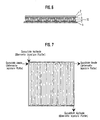
- a bipolar plate 10 formed in this way is shown in FIG. It can be seen that the larger channels of each side mesh like a zipper.
- the bipolar plate may be formed in this case as a thin film.
- An example of this is shown in FIG. 7.
- Structures are also possible in which the larger channels of one side are not connected to one another (rib structure), so that the crossing is likewise avoided. It is not yet determined which structure is more favorable for which electrode and in which direction the structures are flowed through. This can still be optimized with a view to optimal functioning of the cell.
- the power and gas distributors can also be occupied by the catalyst particles required for the electrochemical reaction.
- the flow and gas distributor can be hydrophobicized to counteract the flooding of the structure with water of reaction.
- the power and gas distributors are pressed directly onto a two-electrode membrane or otherwise assembled with the membrane-electrode assembly into a fuel cell.
Landscapes
- Life Sciences & Earth Sciences (AREA)
- Engineering & Computer Science (AREA)
- Manufacturing & Machinery (AREA)
- Sustainable Development (AREA)
- Sustainable Energy (AREA)
- Chemical & Material Sciences (AREA)
- Chemical Kinetics & Catalysis (AREA)
- Electrochemistry (AREA)
- General Chemical & Material Sciences (AREA)
- Fuel Cell (AREA)
- Inert Electrodes (AREA)
Claims (4)
- Cellule électrochimique, en particulier pile à combustible, constituée d'au moins une cellule unique, dans laquelle une cellule unique comprend les composants suivants :- une membrane électrolytique conductrice d'ions (1) sur les deux faces de laquelle est appliquée respectivement une électrode (2, 3) ;- une structure de répartition de courant et de gaz (6) du côté de l'anode ainsi qu'une structure de répartition de courant et de gaz (7) du côté de la cathode, où chacune des deux structures de répartition de courant et de gaz (6, 7) est disposée immédiatement à côté de l'électrode (2, 3) respective sans intercalation d'un collecteur de courant (4, 5) ou autre, et où les structures de répartition de courant et de gaz (6, 7) ont une structure de canal microscopique avec au moins une des grandeurs de structure :- largeur de canal (b),- intervalle (a) entre canaux voisins,- profondeur de canal,inférieure à 100 µm, où la section des canaux présente des contre-dépouilles et/ou une structure de répartition de courant et de gaz présente au moins deux groupes de canaux avec des surfaces de section différentes.
- Cellule électrochimique selon la revendication 1 caractérisée en ce que dans les structures de répartition de courant et de gaz (6,7), au moins une des grandeurs de structure :- largeur de canal (b),- intervalle (a) entre canaux voisins,- profondeur de canal,est inférieure à 10 µm.
- Cellule électrochimique selon la revendication 1 ou 2 caractérisée en ce que la structure de répartition de courant et de gaz (6) du côté de l'anode d'une cellule ainsi que la structure de répartition de courant et de gaz (7) du côté de la cathode de la cellule voisine sont situées sur des faces différentes du même support (10), pour lesquelles les canaux du groupe à plus grande surface de section de l'une des structures de répartition de courant et de gaz viennent recouvrir les canaux du groupe à plus petite surface de section de l'autre structure de répartition de courant et de gaz.
- Cellule électrochimique selon la revendication 3 caractérisée en ce que le support (10) est une feuille.
Applications Claiming Priority (3)
| Application Number | Priority Date | Filing Date | Title |
|---|---|---|---|
| DE19958405A DE19958405B4 (de) | 1999-12-03 | 1999-12-03 | Elektrochemische Zelle |
| DE19958405 | 1999-12-03 | ||
| PCT/EP2000/012052 WO2001041231A2 (fr) | 1999-12-03 | 2000-11-30 | Cellule electrochimique |
Publications (2)
| Publication Number | Publication Date |
|---|---|
| EP1236235A2 EP1236235A2 (fr) | 2002-09-04 |
| EP1236235B1 true EP1236235B1 (fr) | 2006-10-18 |
Family
ID=7931359
Family Applications (1)
| Application Number | Title | Priority Date | Filing Date |
|---|---|---|---|
| EP00983197A Expired - Lifetime EP1236235B1 (fr) | 1999-12-03 | 2000-11-30 | Cellule electrochimique |
Country Status (4)
| Country | Link |
|---|---|
| EP (1) | EP1236235B1 (fr) |
| AT (1) | ATE343223T1 (fr) |
| DE (2) | DE19958405B4 (fr) |
| WO (1) | WO2001041231A2 (fr) |
Families Citing this family (13)
| Publication number | Priority date | Publication date | Assignee | Title |
|---|---|---|---|---|
| KR100840585B1 (ko) | 2001-02-12 | 2008-06-23 | 더 몰간 크루시블 캄파니 피엘시 | 유동장 플레이트 구조 |
| KR20030012684A (ko) * | 2001-08-03 | 2003-02-12 | 양상식 | 소형 전자기기 및 인체 삽입가능한 초소형 연료전지를이용한 초소형 전원 공급 장치 및 그 제조 방법 |
| DE10155349C2 (de) * | 2001-11-02 | 2003-11-20 | Fraunhofer Ges Forschung | Mikrobrennstoffzellensystem sowie Verfahren zu seiner Herstellung |
| GB2387476B (en) | 2002-06-24 | 2004-03-17 | Morgan Crucible Co | Flow field plate geometries |
| KR100481517B1 (ko) * | 2002-11-18 | 2005-04-07 | 삼성전자주식회사 | 멤스 필터를 가지는 휴대용 연료전지 및 멤스 필터의제작공정 |
| FR2878259B1 (fr) * | 2004-11-19 | 2007-09-07 | Univ Toulouse | Procede de reaction electrochimique et reacteur electrochimique a microcanaux et son procede de fabrication |
| WO2006053962A2 (fr) | 2004-11-19 | 2006-05-26 | Universite Paul Sabatier Toulouse Iii | Procédé de réaction électrochimique et réacteur électrochimique à microcanaux et son procédé de fabrication |
| DE102008009377A1 (de) * | 2008-02-14 | 2009-08-20 | Behr Gmbh & Co. Kg | Bipolarplatte mit einer Kanalstruktur und Verfahren zum Herstellen einer Bipolarplatte |
| DE102012211318A1 (de) * | 2012-06-29 | 2014-01-02 | Siemens Aktiengesellschaft | Elektrischer Energiespeicher |
| DE102012211322A1 (de) * | 2012-06-29 | 2014-01-02 | Siemens Aktiengesellschaft | Elektrischer Energiespeicher |
| DE102012211325A1 (de) * | 2012-06-29 | 2014-01-02 | Siemens Aktiengesellschaft | Elektrischer Energiespeicher |
| DE102018200846A1 (de) * | 2018-01-19 | 2019-07-25 | Audi Ag | Brennstoffzellenplatte, Bipolarplatte und Brennstoffzellenaufbau |
| DE102024206412A1 (de) | 2024-07-08 | 2026-01-08 | Robert Bosch Gesellschaft mit beschränkter Haftung | Elektrochemische Zelle |
Family Cites Families (9)
| Publication number | Priority date | Publication date | Assignee | Title |
|---|---|---|---|---|
| FR2564250B1 (fr) * | 1984-05-11 | 1986-09-12 | Alsthom Atlantique | Ameliorations aux structures des piles a combustible |
| US4988583A (en) * | 1989-08-30 | 1991-01-29 | Her Majesty The Queen As Represented By The Minister Of National Defence Of Her Majesty's Canadian Government | Novel fuel cell fluid flow field plate |
| US5108849A (en) * | 1989-08-30 | 1992-04-28 | Her Majesty The Queen In Right Of Canada, As Represented By The Minister Of National Defence In Her Britannic Majesty's Government Of The United Kingdom Of Great Britain And Northern Ireland | Fuel cell fluid flow field plate |
| US5728446A (en) * | 1993-08-22 | 1998-03-17 | Johnston; Raymond P. | Liquid management film for absorbent articles |
| JPH097615A (ja) * | 1995-06-23 | 1997-01-10 | Tanaka Kikinzoku Kogyo Kk | 燃料電池用ガスプレート、燃料電池及び燃料電池へのガス供給方法 |
| US6290685B1 (en) * | 1998-06-18 | 2001-09-18 | 3M Innovative Properties Company | Microchanneled active fluid transport devices |
| AU1600800A (en) * | 1998-10-29 | 2000-05-22 | 3M Innovative Properties Company | Microstructured flow fields |
| EP1147566A2 (fr) * | 1998-12-30 | 2001-10-24 | Ballard Power Systems Inc. | Plaque a champs d'ecoulement de fluide, pour cellule electrochimique, et procede de fabrication de plaques a champ d'ecoulement de fluide, pour cellules electrochimiques |
| US6361892B1 (en) * | 1999-12-06 | 2002-03-26 | Technology Management, Inc. | Electrochemical apparatus with reactant micro-channels |
-
1999
- 1999-12-03 DE DE19958405A patent/DE19958405B4/de not_active Expired - Fee Related
-
2000
- 2000-11-30 DE DE50013641T patent/DE50013641D1/de not_active Expired - Lifetime
- 2000-11-30 EP EP00983197A patent/EP1236235B1/fr not_active Expired - Lifetime
- 2000-11-30 WO PCT/EP2000/012052 patent/WO2001041231A2/fr not_active Ceased
- 2000-11-30 AT AT00983197T patent/ATE343223T1/de not_active IP Right Cessation
Also Published As
| Publication number | Publication date |
|---|---|
| DE19958405B4 (de) | 2006-08-17 |
| WO2001041231A2 (fr) | 2001-06-07 |
| WO2001041231A3 (fr) | 2002-01-24 |
| DE50013641D1 (de) | 2006-11-30 |
| DE19958405A1 (de) | 2001-06-28 |
| ATE343223T1 (de) | 2006-11-15 |
| EP1236235A2 (fr) | 2002-09-04 |
Similar Documents
| Publication | Publication Date | Title |
|---|---|---|
| DE69430634T2 (de) | Elektrochemisches apparat | |
| DE69013626T2 (de) | Brennstoffzelle mit einer Flüssigkeitsverteilungsplatte. | |
| EP0797847B1 (fr) | Pile a combustible a membrane electrolytique polymere | |
| EP0797848B1 (fr) | Pile a combustible a membrane electrolytique polymere a plaques structurees | |
| DE10393075B4 (de) | Bipolare Platte für Brennstoffzellen mit einem leitenden Schaum als Kühlmittellage, Verfahren zu deren Herstellung und Brennstoffzelle | |
| DE102015224994B4 (de) | Bipolarplattenstruktur für Brennstoffzellen | |
| DE10392176B4 (de) | Separatorplatte für eine PEM-Brennstoffzelle und Verfahren zu deren Herstellung | |
| DE60300858T2 (de) | Pen einer festoxidbrennstoffzelle | |
| DE112004002294B4 (de) | Brennstoffzellensystem und Kathodendiffusionsschicht für ein Brennstoffzellensystem | |
| DE69224116T2 (de) | Festoxidbrennstoffzellensystem | |
| EP1236235B1 (fr) | Cellule electrochimique | |
| DE60301189T2 (de) | Brennstoffzellenstapel mit beheizten Endplatten | |
| DE112006000958B4 (de) | Brennstoffzelle | |
| WO1997001194A1 (fr) | Systeme de cellules electrochimiques a electrolyte solide | |
| DE60214950T2 (de) | Miniaturisierte Feststoffoxyd-Brennstoffzelle | |
| DE4206490C2 (de) | Elektrisch leitfähige Gasverteilerstruktur für eine Brennstoffzelle und Verfahren zu ihrer Herstellung | |
| DE19539959C2 (de) | Brennstoffzellenanordnung | |
| DE4009138A1 (de) | Festelektrolyt-hochtemperatur- brennstoffzellenmodul | |
| EP1093176A2 (fr) | Pile à combustible | |
| EP2130256B1 (fr) | empilement de piles à combustible de construction légère | |
| DE112004001525B4 (de) | PEM-Brennstoffzelle | |
| DE112004002358B4 (de) | Feststoffoxid-Brennstoffzelle | |
| EP1027743A2 (fr) | Procede de production d'une pile a combustible haute temperature | |
| DE10197259B4 (de) | Polymerelektrolyt-Brennstoffzellenstack | |
| EP1224705A1 (fr) | Pile a combustible a reformeur interne, et procede pour la faire fonctionner |
Legal Events
| Date | Code | Title | Description |
|---|---|---|---|
| PUAI | Public reference made under article 153(3) epc to a published international application that has entered the european phase |
Free format text: ORIGINAL CODE: 0009012 |
|
| 17P | Request for examination filed |
Effective date: 20020516 |
|
| AK | Designated contracting states |
Kind code of ref document: A2 Designated state(s): AT BE CH CY DE DK ES FI FR GB GR IE IT LI LU MC NL PT SE TR |
|
| RIN1 | Information on inventor provided before grant (corrected) |
Inventor name: LEDJEFF-HEY, KONSTANTIN DI Inventor name: MATEJCEK, LOTHAR Inventor name: HEINZEL, ANGELIKA |
|
| RAP1 | Party data changed (applicant data changed or rights of an application transferred) |
Owner name: FRAUNHOFER-GESELLSCHAFT ZUR FOERDERUNG DERANGEWAND |
|
| 17Q | First examination report despatched |
Effective date: 20040712 |
|
| GRAP | Despatch of communication of intention to grant a patent |
Free format text: ORIGINAL CODE: EPIDOSNIGR1 |
|
| GRAS | Grant fee paid |
Free format text: ORIGINAL CODE: EPIDOSNIGR3 |
|
| GRAA | (expected) grant |
Free format text: ORIGINAL CODE: 0009210 |
|
| AK | Designated contracting states |
Kind code of ref document: B1 Designated state(s): AT BE CH CY DE DK ES FI FR GB GR IE IT LI LU MC NL PT SE TR |
|
| PG25 | Lapsed in a contracting state [announced via postgrant information from national office to epo] |
Ref country code: IE Free format text: LAPSE BECAUSE OF FAILURE TO SUBMIT A TRANSLATION OF THE DESCRIPTION OR TO PAY THE FEE WITHIN THE PRESCRIBED TIME-LIMIT Effective date: 20061018 Ref country code: NL Free format text: LAPSE BECAUSE OF FAILURE TO SUBMIT A TRANSLATION OF THE DESCRIPTION OR TO PAY THE FEE WITHIN THE PRESCRIBED TIME-LIMIT Effective date: 20061018 Ref country code: FI Free format text: LAPSE BECAUSE OF FAILURE TO SUBMIT A TRANSLATION OF THE DESCRIPTION OR TO PAY THE FEE WITHIN THE PRESCRIBED TIME-LIMIT Effective date: 20061018 |
|
| REG | Reference to a national code |
Ref country code: GB Ref legal event code: FG4D Free format text: NOT ENGLISH |
|
| REG | Reference to a national code |
Ref country code: IE Ref legal event code: FG4D Free format text: LANGUAGE OF EP DOCUMENT: GERMAN Ref country code: CH Ref legal event code: EP |
|
| PG25 | Lapsed in a contracting state [announced via postgrant information from national office to epo] |
Ref country code: CH Free format text: LAPSE BECAUSE OF NON-PAYMENT OF DUE FEES Effective date: 20061130 Ref country code: LI Free format text: LAPSE BECAUSE OF NON-PAYMENT OF DUE FEES Effective date: 20061130 Ref country code: BE Free format text: LAPSE BECAUSE OF NON-PAYMENT OF DUE FEES Effective date: 20061130 Ref country code: MC Free format text: LAPSE BECAUSE OF NON-PAYMENT OF DUE FEES Effective date: 20061130 |
|
| REF | Corresponds to: |
Ref document number: 50013641 Country of ref document: DE Date of ref document: 20061130 Kind code of ref document: P |
|
| RAP2 | Party data changed (patent owner data changed or rights of a patent transferred) |
Owner name: FRAUNHOFER-GESELLSCHAFT ZUR FOERDERUNG DER ANGEWAN |
|
| PG25 | Lapsed in a contracting state [announced via postgrant information from national office to epo] |
Ref country code: SE Free format text: LAPSE BECAUSE OF FAILURE TO SUBMIT A TRANSLATION OF THE DESCRIPTION OR TO PAY THE FEE WITHIN THE PRESCRIBED TIME-LIMIT Effective date: 20070118 Ref country code: DK Free format text: LAPSE BECAUSE OF FAILURE TO SUBMIT A TRANSLATION OF THE DESCRIPTION OR TO PAY THE FEE WITHIN THE PRESCRIBED TIME-LIMIT Effective date: 20070118 |
|
| PG25 | Lapsed in a contracting state [announced via postgrant information from national office to epo] |
Ref country code: ES Free format text: LAPSE BECAUSE OF FAILURE TO SUBMIT A TRANSLATION OF THE DESCRIPTION OR TO PAY THE FEE WITHIN THE PRESCRIBED TIME-LIMIT Effective date: 20070129 |
|
| GBT | Gb: translation of ep patent filed (gb section 77(6)(a)/1977) |
Effective date: 20070117 |
|
| NLT2 | Nl: modifications (of names), taken from the european patent patent bulletin |
Owner name: FRAUNHOFER-GESELLSCHAFT ZUR Effective date: 20070117 |
|
| PG25 | Lapsed in a contracting state [announced via postgrant information from national office to epo] |
Ref country code: PT Free format text: LAPSE BECAUSE OF FAILURE TO SUBMIT A TRANSLATION OF THE DESCRIPTION OR TO PAY THE FEE WITHIN THE PRESCRIBED TIME-LIMIT Effective date: 20070319 |
|
| NLV1 | Nl: lapsed or annulled due to failure to fulfill the requirements of art. 29p and 29m of the patents act | ||
| ET | Fr: translation filed | ||
| REG | Reference to a national code |
Ref country code: IE Ref legal event code: FD4D |
|
| REG | Reference to a national code |
Ref country code: CH Ref legal event code: PL |
|
| PLBE | No opposition filed within time limit |
Free format text: ORIGINAL CODE: 0009261 |
|
| STAA | Information on the status of an ep patent application or granted ep patent |
Free format text: STATUS: NO OPPOSITION FILED WITHIN TIME LIMIT |
|
| 26N | No opposition filed |
Effective date: 20070719 |
|
| BERE | Be: lapsed |
Owner name: FRAUNHOFER-GESELLSCHAFT ZUR FORDERUNG DER ANGEWAN Effective date: 20061130 |
|
| PG25 | Lapsed in a contracting state [announced via postgrant information from national office to epo] |
Ref country code: AT Free format text: LAPSE BECAUSE OF NON-PAYMENT OF DUE FEES Effective date: 20061130 |
|
| PG25 | Lapsed in a contracting state [announced via postgrant information from national office to epo] |
Ref country code: GR Free format text: LAPSE BECAUSE OF FAILURE TO SUBMIT A TRANSLATION OF THE DESCRIPTION OR TO PAY THE FEE WITHIN THE PRESCRIBED TIME-LIMIT Effective date: 20070119 |
|
| PG25 | Lapsed in a contracting state [announced via postgrant information from national office to epo] |
Ref country code: TR Free format text: LAPSE BECAUSE OF FAILURE TO SUBMIT A TRANSLATION OF THE DESCRIPTION OR TO PAY THE FEE WITHIN THE PRESCRIBED TIME-LIMIT Effective date: 20061018 Ref country code: LU Free format text: LAPSE BECAUSE OF NON-PAYMENT OF DUE FEES Effective date: 20061130 |
|
| PG25 | Lapsed in a contracting state [announced via postgrant information from national office to epo] |
Ref country code: CY Free format text: LAPSE BECAUSE OF FAILURE TO SUBMIT A TRANSLATION OF THE DESCRIPTION OR TO PAY THE FEE WITHIN THE PRESCRIBED TIME-LIMIT Effective date: 20061018 |
|
| PGFP | Annual fee paid to national office [announced via postgrant information from national office to epo] |
Ref country code: FR Payment date: 20101130 Year of fee payment: 11 |
|
| PGFP | Annual fee paid to national office [announced via postgrant information from national office to epo] |
Ref country code: IT Payment date: 20101126 Year of fee payment: 11 Ref country code: GB Payment date: 20101123 Year of fee payment: 11 |
|
| REG | Reference to a national code |
Ref country code: DE Ref legal event code: R084 Ref document number: 50013641 Country of ref document: DE Effective date: 20111117 |
|
| GBPC | Gb: european patent ceased through non-payment of renewal fee |
Effective date: 20111130 |
|
| REG | Reference to a national code |
Ref country code: FR Ref legal event code: ST Effective date: 20120731 |
|
| PG25 | Lapsed in a contracting state [announced via postgrant information from national office to epo] |
Ref country code: IT Free format text: LAPSE BECAUSE OF NON-PAYMENT OF DUE FEES Effective date: 20111130 |
|
| PG25 | Lapsed in a contracting state [announced via postgrant information from national office to epo] |
Ref country code: GB Free format text: LAPSE BECAUSE OF NON-PAYMENT OF DUE FEES Effective date: 20111130 |
|
| PG25 | Lapsed in a contracting state [announced via postgrant information from national office to epo] |
Ref country code: FR Free format text: LAPSE BECAUSE OF NON-PAYMENT OF DUE FEES Effective date: 20111130 |
|
| REG | Reference to a national code |
Ref country code: DE Ref legal event code: R082 Ref document number: 50013641 Country of ref document: DE Ref country code: DE Ref legal event code: R081 Ref document number: 50013641 Country of ref document: DE Owner name: MATEJCEK, LOTHAR, DR., DE Free format text: FORMER OWNER: FRAUNHOFER-GESELLSCHAFT ZUR FOERDERUNG DER ANGEWANDTEN FORSCHUNG E.V., 80686 MUENCHEN, DE |
|
| PGFP | Annual fee paid to national office [announced via postgrant information from national office to epo] |
Ref country code: DE Payment date: 20160126 Year of fee payment: 16 |
|
| REG | Reference to a national code |
Ref country code: DE Ref legal event code: R119 Ref document number: 50013641 Country of ref document: DE |
|
| PG25 | Lapsed in a contracting state [announced via postgrant information from national office to epo] |
Ref country code: DE Free format text: LAPSE BECAUSE OF NON-PAYMENT OF DUE FEES Effective date: 20170601 |