EP1236321B1 - Egaliseur adaptatif multi-voies - Google Patents
Egaliseur adaptatif multi-voies Download PDFInfo
- Publication number
- EP1236321B1 EP1236321B1 EP00990034A EP00990034A EP1236321B1 EP 1236321 B1 EP1236321 B1 EP 1236321B1 EP 00990034 A EP00990034 A EP 00990034A EP 00990034 A EP00990034 A EP 00990034A EP 1236321 B1 EP1236321 B1 EP 1236321B1
- Authority
- EP
- European Patent Office
- Prior art keywords
- mode
- convergence
- equalizer
- reception mode
- recursive
- Prior art date
- Legal status (The legal status is an assumption and is not a legal conclusion. Google has not performed a legal analysis and makes no representation as to the accuracy of the status listed.)
- Expired - Lifetime
Links
- 230000003044 adaptive effect Effects 0.000 title description 2
- 238000004891 communication Methods 0.000 claims description 10
- 238000012937 correction Methods 0.000 claims description 9
- 238000011144 upstream manufacturing Methods 0.000 claims description 9
- 230000001360 synchronised effect Effects 0.000 claims description 5
- 238000011156 evaluation Methods 0.000 claims 1
- 230000006870 function Effects 0.000 description 21
- 230000005540 biological transmission Effects 0.000 description 13
- 238000000034 method Methods 0.000 description 12
- 238000010586 diagram Methods 0.000 description 10
- 230000006978 adaptation Effects 0.000 description 8
- NKAAEMMYHLFEFN-UHFFFAOYSA-M monosodium tartrate Chemical compound [Na+].OC(=O)C(O)C(O)C([O-])=O NKAAEMMYHLFEFN-UHFFFAOYSA-M 0.000 description 7
- 230000008859 change Effects 0.000 description 5
- 238000012546 transfer Methods 0.000 description 5
- 230000007423 decrease Effects 0.000 description 4
- 235000021183 entrée Nutrition 0.000 description 4
- 230000004048 modification Effects 0.000 description 4
- 238000012986 modification Methods 0.000 description 4
- 239000013598 vector Substances 0.000 description 4
- 101100210170 Saccharomyces cerevisiae (strain ATCC 204508 / S288c) VRP1 gene Proteins 0.000 description 3
- 230000008901 benefit Effects 0.000 description 3
- 238000011084 recovery Methods 0.000 description 3
- 230000001427 coherent effect Effects 0.000 description 2
- 208000038004 exacerbated respiratory disease Diseases 0.000 description 2
- 230000010363 phase shift Effects 0.000 description 2
- 230000008569 process Effects 0.000 description 2
- 230000004044 response Effects 0.000 description 2
- 230000002441 reversible effect Effects 0.000 description 2
- 230000007704 transition Effects 0.000 description 2
- 238000007476 Maximum Likelihood Methods 0.000 description 1
- 238000010420 art technique Methods 0.000 description 1
- 230000006399 behavior Effects 0.000 description 1
- 230000000903 blocking effect Effects 0.000 description 1
- 239000000969 carrier Substances 0.000 description 1
- 230000015556 catabolic process Effects 0.000 description 1
- 230000001186 cumulative effect Effects 0.000 description 1
- 238000006731 degradation reaction Methods 0.000 description 1
- 238000001678 elastic recoil detection analysis Methods 0.000 description 1
- 238000001914 filtration Methods 0.000 description 1
- 238000005194 fractionation Methods 0.000 description 1
- 230000006872 improvement Effects 0.000 description 1
- 239000003607 modifier Substances 0.000 description 1
- 238000005457 optimization Methods 0.000 description 1
- 230000001575 pathological effect Effects 0.000 description 1
- 230000000135 prohibitive effect Effects 0.000 description 1
- 230000033764 rhythmic process Effects 0.000 description 1
- 238000005070 sampling Methods 0.000 description 1
- 230000002123 temporal effect Effects 0.000 description 1
- 238000013519 translation Methods 0.000 description 1
- 238000011282 treatment Methods 0.000 description 1
Images


Classifications
-
- H—ELECTRICITY
- H04—ELECTRIC COMMUNICATION TECHNIQUE
- H04L—TRANSMISSION OF DIGITAL INFORMATION, e.g. TELEGRAPHIC COMMUNICATION
- H04L25/00—Baseband systems
- H04L25/02—Details ; arrangements for supplying electrical power along data transmission lines
- H04L25/03—Shaping networks in transmitter or receiver, e.g. adaptive shaping networks
- H04L25/03006—Arrangements for removing intersymbol interference
- H04L25/03012—Arrangements for removing intersymbol interference operating in the time domain
- H04L25/03019—Arrangements for removing intersymbol interference operating in the time domain adaptive, i.e. capable of adjustment during data reception
- H04L25/03057—Arrangements for removing intersymbol interference operating in the time domain adaptive, i.e. capable of adjustment during data reception with a recursive structure
- H04L25/0307—Arrangements for removing intersymbol interference operating in the time domain adaptive, i.e. capable of adjustment during data reception with a recursive structure using blind adaptation
-
- H—ELECTRICITY
- H04—ELECTRIC COMMUNICATION TECHNIQUE
- H04L—TRANSMISSION OF DIGITAL INFORMATION, e.g. TELEGRAPHIC COMMUNICATION
- H04L1/00—Arrangements for detecting or preventing errors in the information received
- H04L1/02—Arrangements for detecting or preventing errors in the information received by diversity reception
- H04L1/06—Arrangements for detecting or preventing errors in the information received by diversity reception using space diversity
-
- H—ELECTRICITY
- H04—ELECTRIC COMMUNICATION TECHNIQUE
- H04L—TRANSMISSION OF DIGITAL INFORMATION, e.g. TELEGRAPHIC COMMUNICATION
- H04L1/00—Arrangements for detecting or preventing errors in the information received
- H04L1/20—Arrangements for detecting or preventing errors in the information received using signal quality detector
-
- H—ELECTRICITY
- H04—ELECTRIC COMMUNICATION TECHNIQUE
- H04L—TRANSMISSION OF DIGITAL INFORMATION, e.g. TELEGRAPHIC COMMUNICATION
- H04L25/00—Baseband systems
- H04L25/02—Details ; arrangements for supplying electrical power along data transmission lines
- H04L25/03—Shaping networks in transmitter or receiver, e.g. adaptive shaping networks
- H04L25/03006—Arrangements for removing intersymbol interference
- H04L25/03012—Arrangements for removing intersymbol interference operating in the time domain
- H04L25/03019—Arrangements for removing intersymbol interference operating in the time domain adaptive, i.e. capable of adjustment during data reception
- H04L25/03057—Arrangements for removing intersymbol interference operating in the time domain adaptive, i.e. capable of adjustment during data reception with a recursive structure
-
- H—ELECTRICITY
- H04—ELECTRIC COMMUNICATION TECHNIQUE
- H04L—TRANSMISSION OF DIGITAL INFORMATION, e.g. TELEGRAPHIC COMMUNICATION
- H04L25/00—Baseband systems
- H04L25/02—Details ; arrangements for supplying electrical power along data transmission lines
- H04L25/03—Shaping networks in transmitter or receiver, e.g. adaptive shaping networks
- H04L25/03006—Arrangements for removing intersymbol interference
- H04L25/03012—Arrangements for removing intersymbol interference operating in the time domain
- H04L25/03019—Arrangements for removing intersymbol interference operating in the time domain adaptive, i.e. capable of adjustment during data reception
- H04L25/03057—Arrangements for removing intersymbol interference operating in the time domain adaptive, i.e. capable of adjustment during data reception with a recursive structure
- H04L25/03063—Arrangements for removing intersymbol interference operating in the time domain adaptive, i.e. capable of adjustment during data reception with a recursive structure using fractionally spaced delay lines or combinations of fractionally and integrally spaced taps
-
- H—ELECTRICITY
- H04—ELECTRIC COMMUNICATION TECHNIQUE
- H04B—TRANSMISSION
- H04B7/00—Radio transmission systems, i.e. using radiation field
- H04B7/02—Diversity systems; Multi-antenna system, i.e. transmission or reception using multiple antennas
- H04B7/04—Diversity systems; Multi-antenna system, i.e. transmission or reception using multiple antennas using two or more spaced independent antennas
- H04B7/08—Diversity systems; Multi-antenna system, i.e. transmission or reception using multiple antennas using two or more spaced independent antennas at the receiving station
-
- H—ELECTRICITY
- H04—ELECTRIC COMMUNICATION TECHNIQUE
- H04L—TRANSMISSION OF DIGITAL INFORMATION, e.g. TELEGRAPHIC COMMUNICATION
- H04L25/00—Baseband systems
- H04L25/02—Details ; arrangements for supplying electrical power along data transmission lines
- H04L25/03—Shaping networks in transmitter or receiver, e.g. adaptive shaping networks
- H04L25/03006—Arrangements for removing intersymbol interference
- H04L2025/0335—Arrangements for removing intersymbol interference characterised by the type of transmission
- H04L2025/03375—Passband transmission
-
- H—ELECTRICITY
- H04—ELECTRIC COMMUNICATION TECHNIQUE
- H04L—TRANSMISSION OF DIGITAL INFORMATION, e.g. TELEGRAPHIC COMMUNICATION
- H04L25/00—Baseband systems
- H04L25/02—Details ; arrangements for supplying electrical power along data transmission lines
- H04L25/03—Shaping networks in transmitter or receiver, e.g. adaptive shaping networks
- H04L25/03006—Arrangements for removing intersymbol interference
- H04L2025/03433—Arrangements for removing intersymbol interference characterised by equaliser structure
- H04L2025/03439—Fixed structures
- H04L2025/03445—Time domain
- H04L2025/03471—Tapped delay lines
- H04L2025/03509—Tapped delay lines fractionally spaced
-
- H—ELECTRICITY
- H04—ELECTRIC COMMUNICATION TECHNIQUE
- H04L—TRANSMISSION OF DIGITAL INFORMATION, e.g. TELEGRAPHIC COMMUNICATION
- H04L25/00—Baseband systems
- H04L25/02—Details ; arrangements for supplying electrical power along data transmission lines
- H04L25/03—Shaping networks in transmitter or receiver, e.g. adaptive shaping networks
- H04L25/03006—Arrangements for removing intersymbol interference
- H04L2025/03433—Arrangements for removing intersymbol interference characterised by equaliser structure
- H04L2025/03535—Variable structures
- H04L2025/03547—Switching between time domain structures
- H04L2025/03566—Switching between time domain structures between different tapped delay line structures
Definitions
- the present invention relates to equalization devices (or equalizer) for receivers of digital communications systems Multi-channel.
- receivers have a number of functions including demodulation, that is to say the baseband translation of the received signal, equalization, synchronization (rhythm and carrier), decision and channel decoding.
- Equalization in its temporal version, essentially consists of reduce symbol interference (IES), a phenomenon linked to the fact that overall the communications chain does not satisfy what it is agreed to call the Nyquist criterion. This may be due to improper filtering strategy, poor choice of sampling time or of a multipath propagation phenomenon. This is especially the case on radio-mobile channels, on ionospheric channels or tropospheric and on underwater acoustic channels.
- IES reduce symbol interference
- a system of communications can be viewed schematically as a source transmitting, at a 1 / T rate and through an equivalent discrete channel, discrete value symbols in a finite dimensional alphabet.
- This cadence is called modulation speed and is expressed in Baud, T designating the time interval between the emission of two symbols successive.
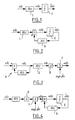
- FIG. 1 The block diagram of a transverse equalizer is illustrated on the FIG. 1, on which a filter 1 of transfer function B (z) has been shown, as well as the decision circuit, referenced by 2, located downstream of said filter 1.
- adaptive equalization is done conventionally in two stages. During the first, the device is piloted by a learning sequence, long enough to guarantee convergence, then, in the second step, it becomes self-adaptive, that's to say that he steers himself from his own decisions, with all the risks inherent in this strategy.
- the behavior of the device had to be checked periodically (or better permanently) so as to avoid pathological functioning of the equalizer.
- a general aim of the invention is to propose a technique to solve this problem elegantly.
- This new temporal equalizer has two operating modes, adapted to the severity of the transmission channel.
- the device In the initial mode, called convergence and shown in Figure 3, the device consists of the cascade of a purely recursive whitening filter 4, of a transverse filter 5, an automatic gain control (AGC) 6 and a phase corrector 7.
- AGC automatic gain control
- the originality of the device is linked to the fact that each stage is adapted according to a specific criterion, which gives it both robustness and speed of convergence.
- An object of the invention is to propose a multi-channel equalizer, in particular spatio-temporal (i.e. an equalizer able to exploit the signals detected simultaneously by several sensors in parallel), which is particularly efficient.
- the invention provides a device according to claim 1.
- the invention also relates to an equalization device of the type fractional, in which the data received is distributed by fractionation on several channels, characterized in that it consists of a device of the aforementioned type.
- Such a space-time equalizer is self-taught with feedback from variable configuration. Based on a signal developed in line such as estimated mean square error, or signal kurtosis equalizer output or, more generally, any function relevant cost (Godard [6], Shalvi & Weinstein [8], Shtrom & Fan [11], ...), the equalizer is “optimally” configured in terms of structure and optimality criteria. In its initial operating mode, called mode of convergence, the device is linear and recursive while, in its normal operating mode, called tracking mode, this device becomes the classic space-time ERD driven by its own decisions. The transition from one to the other of these two configurations is perfectly reversible, which makes it particularly attractive in the case of canals not stationary.
- the device proposed by the invention allows achieve very interesting performances both in terms of convergence than in pursuit. This essential property makes it possible to adapt to fluctuations in the canal in severe situations, unlike conventional equalizers of the prior art. From this point of view, the device proposed by the invention is particularly well suited to non-stationary channels such as radio mobile channels, ionospheric, tropospheric and acoustic submarines.
- the multi-channel equalization device proposed by the invention presents two different structures depending on whether one is in convergence (mode 1) or in tracking mode (mode 2), i.e. in normal operating regime. These two structures are illustrated by Figures 5 and 6.
- the place of the transverse filters and recursive is modified so that the device is configured in ERD conventional space-time ( Figure 6).
- the global optimality criterion then becomes that of the minimization of the mean square error (MSE) estimated.
- MSE mean square error
- the CAG is generally inhibited, i.e. blocked at the value prior to the structural modification. We are therefore witnessing a modification structural and a change in optimality criteria.
- the CAG can be located directly upstream or downstream of the phase corrector, or upstream or downstream of the filter purely recursive.
- the phase corrector responsible for performing the "carrier recovery" operation according to the Anglo-Saxon terminology
- other criteria more robust using current art techniques can also be used.
- Mode 1 convergence mode and / or difficult reception periods.
- CAG carrier recovery
- the gain g of the device 11 is updated according to a blind criterion, the recursive filters on a quadratic criterion and the transverse filters on a criterion involving statistics of order greater than two.
- a blind criterion For updating the coefficients of the transverse filters, several algorithms can be used and in particular those of Godard [6], Shalvi & Weinstein [8], Shtrom & Fan [11], etc.
- Carrier recovery or phase correction i.e. the estimation of the phase error and its compensation in the form of a complex multiplication by exp (-j ⁇ and), is carried out for example according to a criterion minimization of estimated mean square error.
- the error signal elaborated can then be filtered so as to fall on a device of the second order (or of order greater than 2 if necessary).
- This device can also be located at various points in the chain due to the linearity of the device.
- phase correction can be controlled by decisions, again than other more robust criteria, exploiting the symmetry of the constellation of the signal emitted, could be considered.
- the others functions are optimized based on criteria that do not rely on the decisions made by the appropriate system (threshold circuit).
- This first step is, therefore, perfectly self-taught (blind, not supervised).
- each of the elementary devices has a appropriate optimality criterion, which gives the whole a very robust.
- Mode 2 easy tracking mode and / or reception periods.
- the new structure obtained is that of the conventional space-time ERD, driven by decisions, according to the criterion of minimization of the estimated mean square error. Furthermore, if the decided data is judged to be of low likelihood, we can then choose to reinject the signal w (k) at the input of the decision circuit into the filter A (z), in place of the decided data d and (k).
- the space-time equalizer presents two different operating modes associated with different structures and optimality criteria.
- the optimization criterion used for the adaptation of the recursive filter is the minimization of the cost function:
- Godard The criteria used for updating are, without limitation, those of Godard [6], Shalvi & Weinstein [8] or Shtrom and Fan [11].
- Godard the cost function defined by Godard is as follows:
- the reference coefficient can be chosen equal to 1 / P for each of the filters B i , while its position is left free.
- the position of these coefficients which conditions the delay in restoring the equalizer, is chosen so that these filters are more likely to have an anticausal tendency.
- ⁇ ( k ) ⁇ ( k - 1) + ⁇ ⁇ e ( k ) With ⁇ ⁇ an appropriate adaptation step.
- the gain control device is not essential, it may be advantageous in certain cases to provide for it. Again, given the linearity of the structure, the position of this device can be chosen arbitrarily. One position among others is that shown in FIG. 5.
- a signal to assess the level of performance of the equalizer is generated online.
- M DD ( k ) ⁇ M DD ( k -1) + (1- ⁇ ) d ( k ) - w ( k ) 2 or any other cost function developed according to the same principle, for example and to illustrate the point, that of Godard [6] estimated according to: Where ⁇ denotes a forgetting factor.
- the equalizer when the estimated MSE M DD (k) is greater than a threshold M 0 , the equalizer is in convergence mode while on the contrary when it is less than M 0 , it is in tracking mode.
- the threshold should be chosen small enough.
- This operating mode begins when a signal produced in line such that the estimated MSE crosses a threshold adapted to the modulation used (for example 0.25 for MDP4). In this case, the position of the cross filters and the recursive filter to obtain the space-time ERD conventional.
- the equalizer goes from a linear recursive structure to a non-linear recursive structure and vice versa depending on the severity context.
- the criterion is then unique, except know the minimization of the estimated MSE.
- This criterion is used to updating of all equalizer parameters, using an algorithm stochastic gradient or recursive least squares (Recursive Least Square) or any other algorithm corresponding to the current state of the art.
- the automatic gain control characterized by g is generally blocked at its previous value, this function then being automatically performed by the different transverse filters. However, the phase corrector is maintained, but its position can also be changed in accordance in the diagram of figure 6.
- this criterion is the most relevant of the quadratic criteria.
- the relevant criterion for the adaptation of the vector A of the recursive filter is the minimization of the following cost function:
- the two operating modes have been described a self-learning space-time ERD conforming to an embodiment possible of the invention.
- Previously updated achievements developed arise from the stochastic gradient algorithm. Naturally, they can also be obtained by a technique of least squares type, fast least squares or any other technique corresponding to the current state of the art.
- the level of performance achieved by this device is remarkable because in case of degradation of the channel, the device is then configured automatically in convergence mode. On the contrary as soon as the channel improves, which is detected from an online signal, our device configures itself in tracking mode and so on.
- fractional type equalizers fractional spaced equalizers
- T time samples spaced with an elementary duration less than T, for example T / 2.
- the discounting equations are those of conventional fractional ERD corresponding to the state of the art.
- the device described above is directly applicable to continuous data communications systems and transmission systems in packet mode (blocks, bursts, bursts). For this last mode of transmission, just repeat the equalization process of the block as many times as necessary.
- the basic idea is then very simple. A first pass is made on the block in question (packet). In these conditions, the parameters (of the equalizer) estimated at the end of this pass are then closer to their final values. So, the next iteration is carried out by initializing the parameters of the device with the values estimated at the end of the previous iteration and so on. By operating a certain number of passes, typically 4 or 5, we arrive at a result quite exceptional.
- the types of modulations concerned by this invention are all linear modulations and in particular amplitude modulations (Pulse Amplitude Modulation), the amplitude modulations according to two quadrature carriers (MAQ), phase modulations (MDP-M) as well than certain frequency modulations (GMSK, etc.).
- Pulse Amplitude Modulation Pulse Amplitude Modulation
- MAQ the amplitude modulations according to two quadrature carriers
- MDP-M phase modulations
- GMSK frequency modulations
- the learning sequence has 1000 symbols.
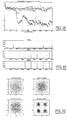
- the different graphs describe in particular the evolution of the estimated MSE from the data decided.
- the signal obtained by passing the decided data d (k) in the correlator adapted to the transmitted sequence (white sequence of length maximum with 2047 symbols) in the case of 1, 2 or 4 sensors.
- the third type of graph describes the input constellations and output equalizers with 1, 2 or 4 sensors respectively.
- the space-time DRE object of the invention is an innovative technique with very interesting performances on a most severe transmission channel.
Landscapes
- Engineering & Computer Science (AREA)
- Computer Networks & Wireless Communication (AREA)
- Signal Processing (AREA)
- Power Engineering (AREA)
- Quality & Reliability (AREA)
- Cable Transmission Systems, Equalization Of Radio And Reduction Of Echo (AREA)
- Filters That Use Time-Delay Elements (AREA)
- Digital Transmission Methods That Use Modulated Carrier Waves (AREA)
Description
- il comporte des moyens pour modifier les critères d'actualisation des parties transverse et récursive que le dispositif fonctionne en mode normal ou en mode de convergence ou de réceptions difficiles.
- en mode de convergence ou de réceptions difficiles, les filtres récursifs sont actualisés selon un critère quadratique, les filtres transverses étant actualisés selon un critère statistique d'ordre supérieur à deux.
- il comporte des moyens pour le piloter, en mode de poursuite ou de réceptions faciles, de façon à minimiser l'erreur quadratique moyenne estimée.
- le degré de performance est déterminé en fonction d'une estimation de l'erreur quadratique moyenne.
- en mode de convergence, les moyens de correction de phase sont disposés au voisinage immédiat des moyens de décisions.
- il comporte des moyens de contrôle automatique de gain.
- en mode de poursuite ou de réceptions faciles, les moyens de contrôle automatique de gain sont constitués par les moyens formant filtres transverses
- en mode de convergence, les moyens de contrôle automatique de gain est situé en amont des filtres récursifs.
- la figure 1 est un schéma de principe d'un égaliseur linéaire transverse temporel.
- la figure 2 est un schéma de principe d'un égaliseur à retour de décision temporel.
- la figure 3 est un schéma qui illustre la structure, en mode de convergence, d'un égaliseur temporel précédemment proposé [12].
- la figure 4 est un schéma qui illustre la structure, en mode de poursuite, du même égaliseur temporel.
- la figure 5 est un schéma qui illustre la structure, en mode de convergence, d'un égaliseur spatio-temporel conforme à un mode de réalisation possible pour l'invention.
- la figure 6 est un schéma qui illustre la structure, en mode de poursuite, d'un égaliseur spatio-temporel conforme à un mode de réalisation possible pour l'invention.
- la figure 7 est un schéma qui illustre la structure, en mode de convergence, d'un égaliseur spatio-temporel fractionné conforme à un mode de réalisation possible pour l'invention.
- la figure 8 est un schéma qui illustre la structure, en mode de convergence, d'un égaliseur spatio-temporel fractionné conforme à un mode de réalisation possible pour l'invention.
- les figures 9 à 11 sont des graphes sur lesquels on a respectivement porté des courbes d'erreur quadratique moyenne, de sortie de corrélateur ainsi que des constellations d'entrée et de sortie dans le cas d'un égaliseur à retour de décision entraíné synchrone, pour un, deux et quatre voies de réception.
- les figures 12 à 14 sont des graphes sur lesquels on a respectivement porté des courbes d'erreur quadratique moyenne, de sortie de corrélateur ainsi que des constellations d'entrée et de sortie dans le cas d'un égaliseur à retour de décision autodidacte synchrone, pour un, deux et quatre voies de réception.
- les figures 15 à 17 sont des graphes sur lesquels on a respectivement porté des courbes d'erreur quadratique moyenne, de sortie de corrélateur ainsi que des constellations d'entrée et de sortie dans le cas d'un égaliseur à retour de décision entraíné fractionné, pour un, deux et quatre voies de réception.
- les figures 18 à 20 sont des graphes sur lesquels on a respectivement porté des courbes d'erreur quadratique moyenne, de sortie de corrélateur ainsi que des constellations d'entrée et de sortie dans le cas d'un égaliseur à retour de décision autodidacte fractionné, pour un, deux et quatre voies de réception.
Pour i=1, 2, .., P, on a :












Claims (12)
- Dispositif d'égalisation pour systèmes de communication numérique à plusieurs voies de réception, qui comporte des moyens (9) formant filtre transverse pour chacune des voies de réception, des moyens (10) pour la sommation des différentes voies, ainsi qu'une chaíne qui est en aval desdits moyens de sommation et qui comporte des moyens (12) de correction de phase, ledit dispositif d'égalisation comportant des moyens pour évaluer son degré de performance en fonction du signal de sortie dudit dispositif et pour, en fonction du résultat de cette évaluation, commuter d'une structure qui correspond au mode de fonctionnement normal, également appelé mode de poursuite ou de réceptions faciles, à une structure qui correspond à un mode de fonctionnement de convergence ou de réceptions difficiles ou réciproquement,
la structure de mode de convergence ou de réceptions difficiles comprenant sur chacune des voies de réception un filtre purement récursif (8) en amont des moyens formant filtre transverse, ce filtre purement récursif étant commuté en aval (13) des moyens formant filtre transverse en mode de poursuite ou de réceptions faciles,
caractérisé en ce que, dans la structure en mode de convergence ou de réceptions difficiles, le filtre récursif des différentes voies de réception est identique et est adapté par minimisation de la somme cumulée des puissances de sortie, ce filtre récursif étant commuté en aval des moyens de sommation en mode de poursuite ou de réceptions faciles. - Dispositif selon la revendication 1, caractérisé en ce qu'il comporte des moyens pour modifier les critères d'actualisation des parties transverse et récursive que le dispositif fonctionne en mode normal ou en mode de convergence ou de réceptions difficiles.
- Dispositif selon la revendication 2, caractérisé en ce qu'en mode de convergence ou de réceptions difficiles, les filtres récursifs sont actualisés selon un critère quadratique, les filtres transverses étant actualisés selon un critère statistique d'ordre supérieur à deux.
- Dispositif selon l'une des revendications 2 ou 3, caractérisé en ce qu'il comporte des moyens pour le piloter, en mode de poursuite ou de réceptions faciles, de façon à minimiser l'erreur quadratique moyenne estimée.
- Dispositif selon l'une des revendications précédentes, caractérisé en ce que le degré de performance est déterminé en fonction d'une estimation de l'erreur quadratique moyenne.
- Dispositif selon l'une des revendications précédentes, caractérisé en ce qu'en mode de convergence, les moyens de correction de phase sont disposés au voisinage immédiat des moyens de décisions (14).
- Dispositif selon l'une des revendications précédentes, caractérisé en ce qu'il comporte des moyens (11) de contrôle automatique de gain.
- Dispositif selon la revendication 7, caractérisé en ce qu'en mode de poursuite ou de réceptions faciles, les moyens de contrôle automatique de gain sont constitués par les moyens formant filtres transverses
- Dispositif selon la revendication 7, caractérisé en ce qu'en mode de convergence, les moyens de contrôle automatique de gain est situé en amont des filtres récursifs.
- Dispositif d'égalisation de type synchrone, dans lequel les données reçues sont échantillonnées une fois par durée symbole, caractérisé en ce qu'il est constitué par un dispositif selon l'une des revendications précédentes.
- Système de transmission à flot continu de données, caractérisé en ce qu'il comporte un dispositif d'égalisation selon l'une des revendications 1 à 10.
- Système de transmission de données par paquets, caractérisé en ce qu'il comporte un dispositif d'égalisation selon l'une des revendications 1 à 10, les blocs de données étant traités par itérations successives, les paramètres du dispositif étant, à chaque nouvelle itération, initialisés en fonction des valeurs estimées à la fin de l'itération précédente.
Applications Claiming Priority (3)
| Application Number | Priority Date | Filing Date | Title |
|---|---|---|---|
| FR9914844A FR2801753B1 (fr) | 1999-11-25 | 1999-11-25 | Perfectionnements aux dispositifs d'egalisation adaptative pour recuperateurs de systemes de communication numeriques |
| FR9914844 | 1999-11-25 | ||
| PCT/FR2000/003282 WO2001039446A1 (fr) | 1999-11-25 | 2000-11-24 | Egaliseur adaptatif multi-voies |
Publications (2)
| Publication Number | Publication Date |
|---|---|
| EP1236321A1 EP1236321A1 (fr) | 2002-09-04 |
| EP1236321B1 true EP1236321B1 (fr) | 2004-02-18 |
Family
ID=9552536
Family Applications (1)
| Application Number | Title | Priority Date | Filing Date |
|---|---|---|---|
| EP00990034A Expired - Lifetime EP1236321B1 (fr) | 1999-11-25 | 2000-11-24 | Egaliseur adaptatif multi-voies |
Country Status (6)
| Country | Link |
|---|---|
| US (1) | US7251274B1 (fr) |
| EP (1) | EP1236321B1 (fr) |
| JP (1) | JP4736297B2 (fr) |
| DE (1) | DE60008420T2 (fr) |
| FR (1) | FR2801753B1 (fr) |
| WO (1) | WO2001039446A1 (fr) |
Families Citing this family (10)
| Publication number | Priority date | Publication date | Assignee | Title |
|---|---|---|---|---|
| US6731682B1 (en) | 2000-04-07 | 2004-05-04 | Zenith Electronics Corporation | Multipath ghost eliminating equalizer with optimum noise enhancement |
| US6904085B1 (en) | 2000-04-07 | 2005-06-07 | Zenith Electronics Corporation | Multipath ghost eliminating equalizer with optimum noise enhancement |
| US7305026B1 (en) | 2000-04-07 | 2007-12-04 | Zenith Electronics Corporation | Multipath ghost eliminating equalizer with optimum noise enhancement |
| US6754262B1 (en) | 2000-04-07 | 2004-06-22 | Zenith Electronics Corporation | Multipath ghost eliminating equalizer with optimum noise enhancement |
| WO2001078339A1 (fr) * | 2000-04-07 | 2001-10-18 | Zenith Electronics Corporation | Egaliseur multibranche |
| AU2003903826A0 (en) | 2003-07-24 | 2003-08-07 | University Of South Australia | An ofdm receiver structure |
| US8605830B2 (en) * | 2010-07-30 | 2013-12-10 | National Instruments Corporation | Blind carrier/timing recovery and detection of modulation scheme |
| WO2014071210A1 (fr) * | 2012-11-02 | 2014-05-08 | The Board Of Trustees Of The Leland Stanford Junior University | Schémas de codage pour des radios de recouvrement cognitives |
| WO2015068198A1 (fr) * | 2013-11-05 | 2015-05-14 | マークデバイシス株式会社 | Circuit de reproduction de fonction de transfert et circuit de déphasage à commande collective |
| CN108667522B (zh) * | 2017-03-30 | 2020-12-11 | 深圳市中兴微电子技术有限公司 | 一种实现相位跳变检测与纠正的方法及装置 |
Family Cites Families (8)
| Publication number | Priority date | Publication date | Assignee | Title |
|---|---|---|---|---|
| FR2556530B1 (fr) * | 1983-10-28 | 1986-04-04 | Telediffusion Fse | Dispositif de correction d'echos, notamment pour systeme de diffusion de donnees |
| JP3033308B2 (ja) * | 1991-12-25 | 2000-04-17 | 松下電器産業株式会社 | 合成ダイバーシチ受信機 |
| US5513214A (en) * | 1992-03-05 | 1996-04-30 | Loral Federal Systems Company | System and method of estimating equalizer performance in the presence of channel mismatch |
| JP3287971B2 (ja) * | 1995-01-31 | 2002-06-04 | 松下電器産業株式会社 | データ受信装置 |
| GB9508661D0 (en) * | 1995-04-28 | 1995-06-14 | Ionica Int Ltd | Adaptive filter |
| FR2738967B1 (fr) * | 1995-09-15 | 1997-12-05 | France Telecom | Dispositif d'egalisation adaptatif pour systemes de communications numeriques |
| US6314147B1 (en) * | 1997-11-04 | 2001-11-06 | The Board Of Trustees Of The Leland Stanford Junior University | Two-stage CCI/ISI reduction with space-time processing in TDMA cellular networks |
| FR2831717A1 (fr) * | 2001-10-25 | 2003-05-02 | France Telecom | Methode et systeme d'elimination d'interference pour antenne multicapteur |
-
1999
- 1999-11-25 FR FR9914844A patent/FR2801753B1/fr not_active Expired - Fee Related
-
2000
- 2000-11-24 US US10/148,142 patent/US7251274B1/en not_active Expired - Fee Related
- 2000-11-24 WO PCT/FR2000/003282 patent/WO2001039446A1/fr not_active Ceased
- 2000-11-24 DE DE60008420T patent/DE60008420T2/de not_active Expired - Lifetime
- 2000-11-24 EP EP00990034A patent/EP1236321B1/fr not_active Expired - Lifetime
- 2000-11-24 JP JP2001540475A patent/JP4736297B2/ja not_active Expired - Fee Related
Also Published As
| Publication number | Publication date |
|---|---|
| EP1236321A1 (fr) | 2002-09-04 |
| FR2801753A1 (fr) | 2001-06-01 |
| DE60008420D1 (de) | 2004-03-25 |
| FR2801753B1 (fr) | 2002-05-03 |
| JP4736297B2 (ja) | 2011-07-27 |
| WO2001039446A1 (fr) | 2001-05-31 |
| DE60008420T2 (de) | 2005-03-03 |
| US7251274B1 (en) | 2007-07-31 |
| JP2003515970A (ja) | 2003-05-07 |
Similar Documents
| Publication | Publication Date | Title |
|---|---|---|
| EP0850527B1 (fr) | Dispositif multimode d'egalisation adaptive | |
| EP1362447B1 (fr) | Procede et systeme de codage-decodage iteratif de flux de donnees numeriques codees par combinaisons spatio-temporelles, en emission et reception multiple | |
| EP1282968B1 (fr) | Procede et systeme de detection et de decodage iteratif de symboles recus, couple a une reestimation des coefficients du canal de transmission | |
| EP0576359B1 (fr) | Procédé et dispositif égaliseur à retour de décisions pour la transmission par blocs de symboles d'information | |
| EP0146979B1 (fr) | Procédé et dispositif pour la détermination de la position optimale du coefficient de référence d'un égaliseur adaptatif | |
| EP0858181A1 (fr) | Procédé d'égalisation multicapteurs dans un récepteur radioélectrique comportant un nombre déterminé de voies de réception et récepteur correspondant | |
| EP1236321B1 (fr) | Egaliseur adaptatif multi-voies | |
| EP0409756A1 (fr) | Dispositif de réception de données à égalisation différée et récupération de rythme rétroactive | |
| EP1668794A1 (fr) | Procede d emission multi-antennes d un signal par codes espace-temps en bloc, procede de reception et signal correspondant | |
| EP3912317B1 (fr) | Procédé de réception d'un signal soqpsk-tg en décomposition pam | |
| EP0669729B1 (fr) | Procédé permettant une égalisation multivoie dans un récepteur radioélectrique, en présence d'interférences et de multitrajets de propagation | |
| EP1024631A1 (fr) | Egaliseur à retour de décisions pondérées, et procédé d'égalisation correspondant | |
| FR2679721A1 (fr) | Procede d'egalisation adaptative reduisant l'interference intersymbole, et dispositif de reception et application correspondants. | |
| EP0981881B1 (fr) | Dispositif d'egalisation et de decodage pour un canal de transmission numerique selectif en frequence | |
| FR2997809A1 (fr) | Methode et dispositif d'egalisation pour canal de transmission non-lineaire | |
| EP2504963B1 (fr) | Systeme et procede d'emission reception d'un signal numerique sur voie radio | |
| EP1221206B1 (fr) | Procede et dispositif pour demoduler des signaux provenant de multi-utilisateurs | |
| EP2351305B1 (fr) | Procédé de modulation multi-états à phase continue et émetteur mettant en oeuvre le procédé | |
| EP1315347B1 (fr) | Procédé et dispositif d'égalisation utilisant des signaux probes | |
| EP1315346B1 (fr) | Procédé et dispositif d'égalisation par blocs avec interpolation améliorée | |
| EP0797333A1 (fr) | Dispositif et procédé d'égalisation autodidacte d'un signal multiporteuse, et récepteur correspondant | |
| WO2017098170A1 (fr) | Procédé et dispositif de combinaison de trames de symboles complexes | |
| FR2734433A1 (fr) | Procede et egaliseur adaptatif pour egaliser un signal numerique transmis par liaisons hertzienne | |
| FR2779893A1 (fr) | Procede et dispositif d'egalisation aveugle auto-adaptatif | |
| FR2789244A1 (fr) | Egaliseur a retour de decisions ponderees, et procede d'egalisation correspondant |
Legal Events
| Date | Code | Title | Description |
|---|---|---|---|
| PUAI | Public reference made under article 153(3) epc to a published international application that has entered the european phase |
Free format text: ORIGINAL CODE: 0009012 |
|
| 17P | Request for examination filed |
Effective date: 20020611 |
|
| AK | Designated contracting states |
Kind code of ref document: A1 Designated state(s): AT BE CH CY DE DK ES FI FR GB GR IE IT LI LU MC NL PT SE TR |
|
| 17Q | First examination report despatched |
Effective date: 20020917 |
|
| GRAH | Despatch of communication of intention to grant a patent |
Free format text: ORIGINAL CODE: EPIDOS IGRA |
|
| GRAS | Grant fee paid |
Free format text: ORIGINAL CODE: EPIDOSNIGR3 |
|
| GRAA | (expected) grant |
Free format text: ORIGINAL CODE: 0009210 |
|
| AK | Designated contracting states |
Kind code of ref document: B1 Designated state(s): DE FR GB |
|
| REG | Reference to a national code |
Ref country code: GB Ref legal event code: FG4D Free format text: NOT ENGLISH |
|
| REG | Reference to a national code |
Ref country code: IE Ref legal event code: FG4D Free format text: FRENCH |
|
| REF | Corresponds to: |
Ref document number: 60008420 Country of ref document: DE Date of ref document: 20040325 Kind code of ref document: P |
|
| GBT | Gb: translation of ep patent filed (gb section 77(6)(a)/1977) |
Effective date: 20040407 |
|
| REG | Reference to a national code |
Ref country code: IE Ref legal event code: FD4D |
|
| PLBE | No opposition filed within time limit |
Free format text: ORIGINAL CODE: 0009261 |
|
| STAA | Information on the status of an ep patent application or granted ep patent |
Free format text: STATUS: NO OPPOSITION FILED WITHIN TIME LIMIT |
|
| 26N | No opposition filed |
Effective date: 20041119 |
|
| REG | Reference to a national code |
Ref country code: FR Ref legal event code: PLFP Year of fee payment: 16 |
|
| REG | Reference to a national code |
Ref country code: FR Ref legal event code: PLFP Year of fee payment: 17 |
|
| PGFP | Annual fee paid to national office [announced via postgrant information from national office to epo] |
Ref country code: GB Payment date: 20161027 Year of fee payment: 17 Ref country code: DE Payment date: 20161020 Year of fee payment: 17 Ref country code: FR Payment date: 20161024 Year of fee payment: 17 |
|
| REG | Reference to a national code |
Ref country code: DE Ref legal event code: R119 Ref document number: 60008420 Country of ref document: DE |
|
| GBPC | Gb: european patent ceased through non-payment of renewal fee |
Effective date: 20171124 |
|
| REG | Reference to a national code |
Ref country code: FR Ref legal event code: ST Effective date: 20180731 |
|
| PG25 | Lapsed in a contracting state [announced via postgrant information from national office to epo] |
Ref country code: FR Free format text: LAPSE BECAUSE OF NON-PAYMENT OF DUE FEES Effective date: 20171130 Ref country code: DE Free format text: LAPSE BECAUSE OF FAILURE TO SUBMIT A TRANSLATION OF THE DESCRIPTION OR TO PAY THE FEE WITHIN THE PRESCRIBED TIME-LIMIT Effective date: 20180602 |
|
| PG25 | Lapsed in a contracting state [announced via postgrant information from national office to epo] |
Ref country code: GB Free format text: LAPSE BECAUSE OF NON-PAYMENT OF DUE FEES Effective date: 20171124 |