EP1236376B1 - Systeme de suppression de bruit comportant l'annulation d'echos de deux micros - Google Patents
Systeme de suppression de bruit comportant l'annulation d'echos de deux micros Download PDFInfo
- Publication number
- EP1236376B1 EP1236376B1 EP00965419A EP00965419A EP1236376B1 EP 1236376 B1 EP1236376 B1 EP 1236376B1 EP 00965419 A EP00965419 A EP 00965419A EP 00965419 A EP00965419 A EP 00965419A EP 1236376 B1 EP1236376 B1 EP 1236376B1
- Authority
- EP
- European Patent Office
- Prior art keywords
- signal
- adaptive filter
- microphone
- adder
- noise
- Prior art date
- Legal status (The legal status is an assumption and is not a legal conclusion. Google has not performed a legal analysis and makes no representation as to the accuracy of the status listed.)
- Expired - Lifetime
Links
Images


Classifications
-
- H—ELECTRICITY
- H04—ELECTRIC COMMUNICATION TECHNIQUE
- H04R—LOUDSPEAKERS, MICROPHONES, GRAMOPHONE PICK-UPS OR LIKE ACOUSTIC ELECTROMECHANICAL TRANSDUCERS; ELECTRIC HEARING AIDS; PUBLIC ADDRESS SYSTEMS
- H04R1/00—Details of transducers, loudspeakers or microphones
- H04R1/20—Arrangements for obtaining desired frequency or directional characteristics
- H04R1/32—Arrangements for obtaining desired frequency or directional characteristics for obtaining desired directional characteristic only
- H04R1/40—Arrangements for obtaining desired frequency or directional characteristics for obtaining desired directional characteristic only by combining a number of identical transducers
- H04R1/406—Arrangements for obtaining desired frequency or directional characteristics for obtaining desired directional characteristic only by combining a number of identical transducers microphones
Definitions
- the present invention relates to the field of acoustic devices.
- the present invention relates to a noise suppression system for use in noisy environments.
- the primary component of unwanted noise is the direct sound wave d(t) from the noise source.
- the secondary component of unwanted noise is the echo of the direct sound wave off a reflecting surface, such as the exterior surface of a building or an interior wall.
- noise is primarily direct noise.
- echo reflection of the primary sound wave off buildings or walls
- the interior surfaces and surfaces of objects contained inside the enclosed environment generate multiple echoes r(t) of the same sound wave.
- Multiple echoes of the reflected sound wave combined with the direct sound wave d(t) is the noise s(t) captured by the microphone.
- acoustic baffles placed on or in front of reflecting walls and other objects, cut off the reflecting acoustic propagation path.
- Various absorbing materials dissipate incident sound energy by converting it to heat energy. Sound absorbers work well for the high frequency range.
- acoustic baffles are bulky and do not work well for low frequencies. In certain industrial environments such as mining, acoustic baffles are not practical.
- An active noise cancellation system uses a microphone, an amplifier and a loud speaker, in an arrangement to cancel the sound in a particular area, typically the area in the vicinity of an operator.
- the microphone provides a measure of the noise in a local area relatively distant from the direct noise source.
- the amplifier drives the loudspeaker to produce equal amplitude and opposite phase acoustic signal to cancel out the sound in the local area.
- a variation of the above system includes a second microphone disposed at a noise receiving point.
- the output of the second microphone is a measure of the cancellation error, which is used to adjust the coefficients of an adaptive filter in a closed loop recursive system to further reduce the noise received at the second microphone.
- a microphone is placed very close to the acoustic noise source, which is approximated a point source.
- the signal processing circuit produces a phase opposition signal, which is adjustable by adjusting the distance between the microphone and the loudspeaker.
- Such systems are restricted to a point source of acoustic radiation of a single frequency, and do not work well when the noise is produced by large vibrating surfaces that may be vibrating in a complex mode to produce a wide spectrum of frequencies.
- Another type of active noise cancellation system uses a pair of microphones and a headset worn by the operator.
- a first microphone picks up a first sample of the background noise.
- a second microphone placed some distance away from the first microphone picks up a second sample of the background noise.
- the signal from the second microphone is processed in an adaptive filter and combined in opposite phase relationship to the signal from the first microphone.
- the processed second signal from the second microphone tends to cancel the noise signal arriving at the first microphone.
- the headset actively reduces the level of noise reaching the ears, thereby providing ear protection for workers when worn in high noise areas. However, such headsets prevent workers from hearing alarm signals and block speech communication between workers.
- noise suppression systems are used in communications systems to help workers hear speech signals in noisy environments.
- Noise reduction communication systems distinguish the desired speech component from the background noise component of the combined signal. By canceling or reducing the background noise component, the signal-to-noise ratio is increased thereby enhancing the quality of the received speech.
- One type of noise suppression system uses a pair of microphones connected to a headset worn by the operator.
- a first microphone (for voice) picks up a first signal containing the intended speech plus the background noise.
- a second microphone (for noise) placed some distance away from the first microphone, picks up a sample consisting mostly of the background noise and less of the speech signal.
- the signal from the second microphone (background noise) is processed in an adaptive filter and subtracted from the signal from the first microphone (speech plus the background noise) to reduce or cancel the background noise component of the first signal.
- the background noise sample (at the second microphone) is not exactly the same background noise signal that is arriving at the first microphone.
- the function of the adaptive filter is to compensate for the difference in acoustic paths of background noise arriving at the first and second microphones.
- U.S. patent 5,754,665 (see also EP 0 729 288) to Hosoi shows a dual noise canceller with dual microphones and dual adaptive filters intended for use in an automobile telephone speaker system.
- First and second microphones are placed near the driver and passenger, respectively. When one microphone is used for conversation, the other microphone is used for collecting noise, and vice versa.
- a noise-reduced version of the first voice signal is obtained by using one of the adaptive filters.
- the second microphone is used for conversation, the first microphone is used for collecting noise.
- a noise-reduced version of the second voice signal is obtained by using the second adaptive filter.
- the two noise reduced versions are added to form the outgoing telephone voice signal.
- the second microphone should provide a better estimate of the noise to be cancelled in the first microphone.
- each microphone will cause an additional echo to strike the other microphone. That is, the first microphone will act like a speaker (a sound source) transmitting an echo of the sound field striking the second microphone.
- the second microphone will act like a speaker (a sound source) transmitting an echo of the sound field striking the first microphone. Therefore, the signal from the first microphone contains the sum of the background noise plus a reflection of the background noise, which results in a poorer estimate of the background noise to be cancelled.
- the present invention is embodied in a dual microphone noise suppression system in which the echo between the two microphones is substantially canceled or suppressed. Reverberations from one microphone to the other are cancelled by the use of first and second line echo cancellers. Each line echo canceller models the delay and transmission characteristics of the acoustic path between the first and second microphones.
- the present invention is further embodied in an ear set to be worn in the outer ear.
- the ear set is a self-contained molded unit, with integral dual microphones, battery, ear canal speaker, signal processing electronics that is convenient to wear and will not interfere with communication between workers or physical activity while working.
- a noise suppression system in accordance with the present invention acts as an ear protector, canceling substantially all or most of the noise striking the dual microphones of the ear set.
- a noise suppression system in accordance with the present invention acts as a noise suppression communication system, suppressing background noise while allowing communication signals to be heard by the wearer.
- Figure 1 is a general purpose block diagram a dual microphone acoustic noise suppression (ANS) system.
- First and second microphones, mic1 and mic2 are coupled to a dual echo predictive line canceller 10.
- the concept of ANS is based on the cancellation of noise in one microphone by means of the other microphone.
- the electronic portion 10 of an ANS system was first developed using an analog system. Such systems were much too bulky to be fitted into an ear set.
- Each noise source (A or B) projects a different direct sound wave along different paths to mic1 and mic2.
- the acoustic path from noise source A to mic1 is represented by a transfer function E 2 (z).
- the acoustic path from noise source A to mic2 is represented by a transfer function E 1 (z).
- Between mic1 and mic2 the acoustic path is represented by a transfer function E 3 (z).
- FIG. 2 shows an ear set 14 embodying the present invention.
- the ear set 14 contains an ear canal speaker 12, which is coupled to the human ear 36.
- the ear set 14 further includes a pair of microphones, mic1 and mic2 closely mounted on the ear set 14. Sound from a given source 21 reaches mic1 and mic2 by direct paths 26, 16 respectively. Sound from source 21 also reaches mic1 by various reflecting paths.
- a sound wave 28 reflecting off a neighboring wall 23 reaches mic1 as a reflected sound wave 30.
- a sound wave 32 reflecting off a neighboring wall 23 reaches mic1 as a reflected sound wave 34.
- a sound source 40 includes a direct path 44 and a plurality of reflecting paths such as 46A, 46B, 48A, 48B and 50, known as reverberation (or reverberating) noise.
- figure 4 is a simplified representation to the model illustrated in figure 1 where mic1 acts as an echo source generator transmitting the signal toward mic2.
- the dual microphones mic1 and mic2 are fixed on the same axis 72 on either side of the ear set, perpendicular to a direct path 70 to the ear set.
- each of the microphones will receive a reverberant sound.
- a sound wave 64 reflecting off a neighboring wall 53 reaches mic1 as a reflected sound wave 68, which tends to cancel a sound wave 60 reflecting off a neighboring wall 55 reaching mic1 as a reflected sound wave 62.
- a sound wave 52 reflecting off a neighboring wall 53 reaches mic2 as a reflected sound wave 54, which tends to cancel a sound wave 56 reflecting off a neighboring wall 55 reaches mic2 as a reflected sound wave 58.
- All reverberant sound waves will tend to cancel each other at each microphone, except the reverberant sound wave r 3 (t) along the echo path from mic1 to mic2.
- the reverberant sound wave r 3 (t) captured by mic1 is out of phase with the reverberant sound wave -r 3 (t) captured by mic2.
- the received direct sound by each microphone will be a delayed version of the other.
- the direct sound wave d 1 (t) at one microphone is a delayed version of the direct sound wave d 2 (t) at the other microphone.
- FIG 5 A simplified representation of the mutual echoes is illustrated in figures 5 and 6.
- mic2 acts as an echo source generator 512 transmitting the noise signal d ⁇ 2 (t) toward mic1.
- figure 6 the process is reversed, where mic1 is acting as an echo source generator transmitting noise signal d ⁇ 1 (t) toward mic2.
- a line echo canceller is implemented in order to duplicate the noise signal flowing through the inter-microphone acoustic path (E 3 in figure 1).
- the noise captured in mic2 includes the echo from mic1 and vice versa.
- s 1 (t) in figure 5 has a term to be cancelled: i.e., d ⁇ 2 (t) (the delayed version of d 2 (t) including some reverberations) by having an estimate of d 2 (t). Therefore, an Acoustic Noise Suppressor (ANS) and the Line Echo Canceller (LEC) share the common problem of finding the best estimate of the microphone to microphone echo path E 3 (in figure 1).
- ANS Acoustic Noise Suppressor
- LEC Line Echo Canceller
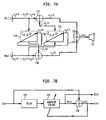
- a noise suppression system formed by a pair of echo line cancellers for use in conjunction with the present invention is shown in figure 7A.
- Mic1 is coupled to a first echo prediction adaptive filter 710 and a first adder 712.
- Mic2 is coupled to a second echo prediction adaptive filter 714 a second adder 718.
- the output of the first adder 712 is used to subtract the predictive noise d ⁇ 2 (t) from s 1 (t).
- the output of the second adder 718 is used to subtract the predictive noise d ⁇ 1 (t) from s 2 (t).
- the residual error terms at the respective outputs of the first and second adders 712, 718 are summed in adder 716 to drive the output speaker 717.
- Suitable analog to digital converters (not shown) sample the microphones at a 48 kHz sampling rate.
- the echo prediction filters 710 and 714 are shown in further detail in figure 7B.
- Each echo prediction filter takes an input signal s(t) and subtracts (in adder 726) a delayed filtered 724 version p(t) of the input signal s(t).
- the delay 722 is selected to be equal to the acoustic delay between mic1 and mic2.
- the filtered version of the input signal is obtained by use of an adaptive filter 724.
- the delayed and filtered signal p(t) is subtracted in adder 726 (subtraction by signed addition). The difference is the error signal e(t) used to adjust the adaptive filter 724 coefficients.
- the adaptive filter 724 models the transfer function E 3 (z)of the acoustic path between mic1 and mic2, in order to generate the predictive noise term, d ⁇ 2 (t).
- Adaptive filtering is a well-known technique useful in many signal processing applications.
- Adaptive filters are typically used in a closed loop system in which some measure of error (an error term) is to be minimized.
- An adaptive filter has an input terminal, an output terminal and an error terminal.
- Adaptive filters internally implement a suitable algorithm (responsive to the error input) to adjust the parameters of the adaptive filter so as to minimize the error term.
- the filtered least means-square error (LMS) algorithm is a well-known method for adapting a filter.
- the LMS algorithm is simple and robust, has been widely adopted in many applications.
- an adaptive filter is implemented using a finite impulse response (FIR) filter using a digital tapped delay line with adjustable filter coefficients.
- the LMS algorithm is used to adjust the values of the filter coefficients responsive to an error input.
- the adaptive filters are used in a closed loop feedback system in which the adaptive filters are adjusted to model the characteristics of the acoustic path between mic1 and mic2.
- the implementation of each half of figure 7A is like a telephone line echo canceller which compensates for the acoustic path coupling between the microphone and ear piece of a telephone handset.
- the parameters of the adaptive filter 710 are set to an initial estimate. To the extent that the output of the adaptive filter 710 is not equal to the delayed version of the same signal, an error term e 1 (t) at the output 719is fed back to adjust the adaptive filter 710. After successive iterations, the parameters of the adaptive filter 710 are adjusted so as to minimize the error term at the output 719.
- the parameters of the adaptive filter 714 are set to an initial estimate. To the extent that the output of the adaptive filter 714 is not equal to the delayed version of the same signal, an error term e 2 (t) at the output 720 is fed back to adjust the adaptive filter 714. After successive iterations, the parameters of the adaptive filter 714 are adjusted so as to minimize the error term at the output 720.
- Each microphone signal mic1, mic2 is used by each respective adaptive filter 714, 710 to generate a replica of the echo called d ⁇ (t), which is subtracted from the other microphone signal (including the echo).
- the echo canceller generates the echo replica by applying the reference signal to an adaptive filter (tapped-delay-line), as shown. At convergence, the adaptive filter's transfer function is identical to that of the echo path between the two microphones.
- the convergence and the stability of the system relies on the stability of the two line echo cancellers.
- the choice of a value for the step size parameter ⁇ (used in the known LMS algorithm) is important for stability.
- a sufficient condition for convergence of the LEC algorithm is given by: 0 ⁇ ⁇ ⁇ 2 ⁇ max ( R xx ) where ⁇ max is the largest eigenvalue of the autocorrelation matrix.
- the system of figure 7A will tend to cancel all noise without discriminating between unwanted sounds (background noise) and wanted sounds (speech).
- wanted sounds e.g., speech
- a speech detector is utilized (not shown).
- the detailed version of figure 7A is an approach for canceling the echo in each microphone uses dual prediction circuits to predict the echoes p 1 (n) and p 2 (n).
- a delay element 812, an adaptive filter 814 and an adder 816 form a first predictor circuit to predict p 1 (n) from mic1 (via analog to digital converter 810).
- a delay element 822, an adaptive filter 824 and an adder 826 form a second predictor circuit to predict p 2 (n) from mic2. (via analog to digital converter 820).
- the output is formed by adders 818, 828 and 830 which drive the speaker 833 via a digital to analog converter 832.
- a delayed 812 version of the mic1 signal is processed in an adaptive filter 814 and subtracted 816 from the signal from mic1.
- the delay 812 is set equal to the acoustic delay between mic1 and mic2.
- the parameters of the adaptive filter 814 have been adjusted so as to model the transmission characteristics of the acoustic path between mic2 and mic1.
- each echo p 1 (n), p 2 (n) is subtracted 828, 818 from the signal s 2 (n), s 1 (n) received from the other microphone.
- the predicted value of the mic2 echo p 1 (n) in mic1 is then subtracted 828 from the mic2 signal.
- the predicted value of the mic1 echo p 2 (n) in mic2 is then subtracted 818 from the mic1 signal.
- an A/D converter 810 converts the signal from mic1 to digital form, which is then delayed in delay element 812.
- the preset value of the delay 812 is a function of the spacing between microphone mic1 and microphone mic2.
- the delay value is set equal to the time it takes a sound wave to travel between mic1 and mic2.
- the delayed signal from mic1 is processed in an adaptive filter 814, which simulates the transfer characteristics of the acoustic path from mic1 to mic2.
- the output of the adaptive filter 814 is subtracted 816 (using a signed addition convention for subtraction) from the mic1 signal.
- the coefficients of the adaptive filter 814 are adjusted using the LMS algorithm.
- the output of the adaptive filter 814 is p 1 (n), a predicted (delayed) version of the echo at mic2 received from mic 1.
- the predicted value of the echo from mic1, p 1 (n), is subtracted from the signal from mic2 in adder 828 (using a signed addition convention for subtraction). In such manner, the (predicted) echo from mic1 arriving at mic2 is subtracted (cancelled) from the mic2 signal, and appears at the output of adder 828.
- A/D converter 820 converts the signal from mic2 to digital form, which is then delayed in delay element 822.
- the preset value of the delay 822 is also a function of the spacing between microphone mic1 and microphone mic2 and is set to the same delay value as delay 812.
- the delayed signal from mic2 is processed in an adaptive filter 824, which simulates the transfer characteristics of the acoustic path from mic2 to mic1.
- the output of the adaptive filter 824 is subtracted 826 (using a signed addition convention for subtraction) from the mic2 signal.
- the coefficients of the adaptive filter 824 are adjusted using the LMS algorithm.
- the output of the adaptive filter 824 is p 2 (n), a predicted (delayed) version of the echo at mic1 received from mic2.
- the predicted value of the echo from mic2, p 2 (n), is subtracted from the signal from mic1 in adder 818 (using a signed addition convention for subtraction). In such manner, the (predicted) echo from mic2 arriving at mic1 is subtracted (cancelled) from the mic1 signal, and appears at the output of adder 818.
- the outputs of adders 818 and 828 are summed in adder 830 and form the signal output to drive speaker 833.
- the circuit of figure 8 is a noise suppression system used primarily for ear protection. Substantially all noise will tend to be cancelled.
- a noise suppression system that allows speech signals to be heard while suppressing background noise is shown in figures 9 and 10.
- the noise suppression stage which consists of dual prediction circuits and adders, is analogous to the noise suppression circuit shown in figure 8.
- respective A/D converters 910, 920, delay elements 912, 922, adaptive filters 914, 924 and adders 916, 926, 918, 928 in figure 9 are connected and operate in the same manner as the corresponding A/D converters 810, 820, delay elements 812, 822, adaptive filters 814, 824 and adders 816, 826, 818, 828 in figure 8.
- the noise suppression circuit is adaptive so long as the speech detector 913 does not detect speech. While speech is not present, respective AND gates 940A, 940 couple the respective error signal outputs of adders 916, 926 to update the adaptive filter coefficients of the adaptive filters 914, 924.
- the output of adders 918 and 928 are connected to the input of a speech processing stage.
- the speech processing stage consists of two adaptive filters 930, 933, adders 932, 936 and 934 and AND gates 940 and 942.
- the speech processing stage conditions speech in independent adaptive filters 930, 933 before combining the processed speech signals in adder 934.
- Figure 10 shows an alternate embodiment of the speech processing stage.
- the operation of the adaptive filters 930, 933 are interrelated.
- the adaptive filters 930, 933 are cross coupled by connecting the output of adder 928 to the input of adder 932 (figure 10) instead of to the input of adder 936 (figure 9).
- the adaptive filters 930, 933 are cross coupled by connecting the output of adder 918 to the input of adder 936 (figure 10) instead of to the input of adder 932 (figure 9).
- a speech detector 913 coupled to mic1 and mic2 indicates when speech is present in the background noise.
- the output of adder 918 is coupled to a first adaptive filter 930 and a first adder 932.
- the output of adder 928 is coupled to a second adaptive filter 933 a second adder 936.
- the output of the first adder 936 is used as the error term e 4 to adjust the parameters of the second adaptive filter 933 via AND gate 942.
- the other input of AND gate 942 is coupled to the signal that indicates speech is present.
- the output of the second adder 932 is used as the error term e 3 to adjust the parameters of the first adaptive filter 930 via AND gate 940.
- the other input of AND gate 940 is coupled to the signal that indicates speech is present.
- the residual error terms e 3 and e 4 at the respective outputs of the first and second adders 936, 932 are subtracted in adder 934 to drive the output speaker 938.
- the speech processing stage enhances the resulting speech signal by taking the difference (e 3 minus e 4 ) between the two adder outputs 932, 936.
- a suitable digital to analog converter converts the output of adder 934 to drive a speaker 938.
- AND gates 940, 940A, 942, 942A permit each respective adaptive filter 930, 914, 933, 924 to use each respective error signal to update the respective coefficients.
- the adaptive filters 930, 914, 933 and 924 are continuously adjusted to cancel all sound as noise. As a result, input noise is cancelled by operation of the circuit.
- the AND gates 940, 940A, 942, 942A are responsive to a speech present indication from the speech detector 913, to suspend the update error function. In other words, when speech is present, the adaptive filters are "frozen" and do not adapt to cancel the desired speech signal.
- the AND gates 940, 940A, 942, 942A force the adaptive filters 930, 914, 933, 924 to stop adapting respective filter coefficients and keep the computed values equal to the values computed just prior to detection of speech. With the adaptive filter coefficients frozen, the subsequent speech is the error signal. Assuming that the background noise does not materially change while speech is present, the system output from the D/A converter to the speaker 938 is substantially equal to the input speech signal with the background noise suppressed.
Landscapes
- Health & Medical Sciences (AREA)
- Otolaryngology (AREA)
- Physics & Mathematics (AREA)
- Engineering & Computer Science (AREA)
- Acoustics & Sound (AREA)
- Signal Processing (AREA)
- Soundproofing, Sound Blocking, And Sound Damping (AREA)
- Cable Transmission Systems, Equalization Of Radio And Reduction Of Echo (AREA)
- Circuit For Audible Band Transducer (AREA)
Claims (12)
- Procédé pour supprimer le bruit acoustique dans un système de communication comportant un premier et un second microphones (Mic1, Mic2) pour recevoir un signal acoustique (S1(t), s2(t)) et un haut-parleur (833, 938) pour générer des signaux acoustiques, dans lequel le bruit est reçu par lesdits premier et second microphones, ledit procédé comprenant :la réception d'un premier signal dudit premier microphone ;la réception d'un second signal dudit second microphone ;le traitement dudit premier signal dans un premier filtre adaptateur (814, 914) pour fournir un premier signal d'écho prédit (p1(n)) ;la soustraction dudit premier signal d'écho prédit dudit premier signal pour fournir un premier signal de commande de filtre adaptateur (e1(n)), ledit premier filtre adaptateur étant sensible audit premier signal de commande de filtre adaptateur pour adapter les paramètres dudit premier filtre adaptateur ;la soustraction dudit premier signal d'écho prédit dudit second signal pour fournir un premier signal de renvoi (-r3(n)) ;le traitement dudit second signal dans un second filtre adaptateur (824, 924) pour fournir un second signal d'écho prédit (p2(n)) ;la soustraction dudit second signal d'écho prédit dudit second signal pour fournir un second signal de commande de filtre adaptateur (e2(n)), ledit second filtre adaptateur étant sensible audit second signal de commande de filtre adaptateur pour adapter les paramètres dudit second filtre adaptateur ;la soustraction dudit second signal d'écho prédit dudit premier signal pour fournir un second signal de renvoi (r3(n)) ;et la soustraction dudit premier signal de renvoi et dudit second signal de renvoi pour former un signal de sortie pour ledit haut-parleur, de telle sorte que le bruit acoustique reçu par lesdits premier et second microphones est sensiblement supprimé,
dans lequel ladite étape de traitement dudit premier signal dans un premier filtre adaptateur pour fournir ledit premier signal d'écho prédit, inclut en outre l'étape consistant à retarder ledit premier signal d'une quantité sensiblement égale au retard de temps d'une onde acoustique se déplaçant dudit second microphone audit premier microphone,
dans lequel ladite étape de traitement dudit premier signal dans un premier filtre adaptateur pour fournir ledit premier signal d'écho prédit, inclut en outre l'étape de réglage dudit premier filtre adaptateur pour avoir sensiblement les mêmes caractéristiques de transfert que le chemin acoustique dudit second microphone audit premier microphone,
dans lequel ladite étape de traitement dudit second signal dans un second filtre adaptateur pour fournir ledit second signal d'écho prédit, inclut en outre l'étape consistant à retarder ledit second signal d'une quantité sensiblement égale au retard de temps d'une onde acoustique se déplaçant dudit premier microphone audit second microphone,
et dans lequel ladite étape de traitement dudit second signal dans un second filtre adaptateur pour fournir ledit second signal d'écho prédit, inclut en outre l'étape de réglage dudit second filtre adaptateur pour avoir sensiblement les mêmes caractéristiques de transfert que le chemin acoustique dudit premier microphone audit second microphone. - Procédé selon la revendication 1, comprenant en outre :la détection de la présence de paroles en réponse aux premier et second signaux ;et l'arrêt du fonctionnement desdits premier et second filtres adaptateurs lorsque des paroles sont détectées.
- Appareil pour supprimer le bruit acoustique, comportant un premier et un second microphones (Mic1, Mic2) pour recevoir un signal acoustique (s1(t), s2(t)) et un haut-parleur (833, 938) pour générer des signaux acoustiques, dans lequel le bruit est reçu par lesdits premier et second microphones, ledit appareil comprenant :des moyens (810, 910) pour recevoir un premier signal dudit premier microphone ;des moyens (820, 920) pour recevoir un second signal dudit second microphone ;des moyens de traitement dudit premier signal dans un premier filtre adaptateur (814, 914) pour fournir un premier signal d'écho prédit (p1(n)) ;des moyens (816, 916) pour soustraire ledit premier signal d'écho prédit dudit premier signal pour fournir un premier signal de commande de filtre adaptateur (e1(n)), ledit premier filtre adaptateur étant sensible audit premier signal de commande de filtre adaptateur pour adapter les paramètres dudit premier filtre adaptateur ;des moyens (828, 928) pour soustraire ledit premier signal d'écho prédit dudit second signal pour fournir un premier signal de renvoi (-r3(n)) ;des moyens de traitement dudit second signal dans un second filtre adaptateur (824, 924) pour fournir un second signal d'écho prédit (p2(n)) ;des moyens (826, 926) pour soustraire ledit second signal d'écho prédit dudit second signal pour fournir un second signal de commande de filtre adaptateur (e2(n)), ledit second filtre adaptateur étant sensible audit second signal de commande de filtre adaptateur pour adapter les paramètres dudit second filtre adaptateur ;des moyens (818, 918) pour soustraire ledit second signal d'écho prédit dudit premier signal pour fournir un second signal de renvoi (r3(n)) ;et des moyens (830, 934) pour soustraire ledit premier signal de renvoi et ledit second signal de renvoi pour former un signal de sortie pour ledit haut-parleur,de telle sorte que le bruit acoustique reçu par lesdits premier et second microphones est sensiblement supprimé,
dans lequel lesdits moyens de traitement dudit premier signal dans un premier filtre adaptateur pour fournir ledit premier signal d'écho prédit, incluent en outre le retardement dudit premier signal d'une quantité sensiblement égale au retard de temps d'une onde acoustique se déplaçant dudit second microphone audit premier microphone,
dans lequel lesdits moyens de traitement dudit premier signal dans un premier filtre adaptateur pour fournir ledit premier signal d'écho prédit, incluent en outre le réglage dudit premier filtre adaptateur pour avoir sensiblement les mêmes caractéristiques de transfert que le chemin acoustique dudit second microphone audit premier microphone,
dans lequel lesdits moyens de traitement dudit second signal dans un second filtre adaptateur pour fournir ledit second signal d'écho prédit, incluent en outre le retardement dudit second signal d'une quantité sensiblement égale au retard de temps d'une onde acoustique se déplaçant dudit premier microphone audit second microphone,
et dans lequel lesdits moyens de traitement dudit second signal dans un second filtre adaptateur pour fournir ledit second signal d'écho prédit, incluent en outre le réglage dudit second filtre adaptateur pour avoir sensiblement les mêmes caractéristiques de transfert que le chemin acoustique dudit premier microphone audit second microphone. - Appareil selon la revendication 3, comprenant en outre :des moyens pour détecter la présence de paroles en réponse aux premier et second signaux ;et des moyens pour arrêter le fonctionnement desdits premier et second filtres adaptateurs lorsque des paroles sont détectées.
- Appareil selon la revendication 3 pour supprimer le bruit acoustique dans un système de communication comprenant un haut-parleur pour générer des signaux acoustiques, ledit appareil comprenant en outre :ledit premier filtre adaptateur comportant une borne d'entrée, une borne de sortie, et une borne de commande, ladite borne d'entrée étant couplée audit premier microphone ;ledit premier additionneur (816, 916) comportant une première et une seconde bornes d'entrée et une borne de sortie, ladite première borne d'entrée étant reliée à ladite borne de sortie dudit premier filtre adaptateur, ladite seconde borne d'entrée étant couplée audit premier microphone et ladite borne de sortie dudit premier additionneur étant reliée à ladite borne de commande dudit premier filtre adaptateur ;ledit second filtre adaptateur comportant une borne d'entrée, une borne de sortie, et une borne de commande, ladite borne d'entrée étant couplée audit second microphone ;ledit second additionneur (826, 926) comportant une première et une seconde bornes d'entrée et une borne de sortie, ladite première borne d'entrée étant reliée à ladite borne de sortie dudit second filtre adaptateur, ladite seconde borne d'entrée étant couplée audit second microphone et ladite borne de sortie dudit second additionneur étant reliée à ladite borne de commande dudit second filtre adaptateur ;ledit troisième additionneur (828, 928) comportant une première et une seconde bornes d'entrée et une borne de sortie, ladite première borne d'entrée dudit troisième additionneur étant reliée à ladite borne de sortie dudit premier filtre adaptateur et ladite seconde borne d'entrée dudit troisième additionneur étant couplée audit second microphone ;ledit quatrième additionneur (818, 918) comportant une première et une seconde bornes d'entrée et une borne de sortie, ladite première borne d'entrée dudit quatrième additionneur étant reliée à ladite borne de sortie dudit second filtre adaptateur et ladite seconde borne d'entrée dudit quatrième additionneur étant couplée audit premier microphone ;et ledit cinquième additionneur (830, 934) comportant une première et une seconde bornes d'entrée et une borne de sortie, ladite première borne d'entrée dudit cinquième additionneur étant couplée à la borne de sortie dudit troisième additionneur, ladite seconde borne d'entrée dudit cinquième additionneur étant couplée à la borne de sortie dudit quatrième additionneur et ladite borne de sortie dudit cinquième additionneur étant couplée audit haut-parleur, de telle sorte que le bruit acoustique reçu par lesdits premier et second microphones est sensiblement supprimé.
- Appareil selon la revendication 5, comprenant en outre un premier élément retardateur (812, 912) comportant des bornes d'entrée et de sortie respectives dans lequel ladite borne d'entrée dudit premier élément retardateur est couplée audit premier microphone et ladite borne de sortie dudit premier élément retardateur est reliée à ladite borne d'entrée dudit premier filtre adaptateur.
- Appareil selon la revendication 6, dans lequel ledit premier filtre adaptateur est réglé de façon à avoir sensiblement les mêmes caractéristiques de transfert que le chemin acoustique dudit second microphone audit premier microphone.
- Appareil selon la revendication 7, comprenant en outre un second élément retardateur (822, 922) comportant des bornes d'entrée et de sortie respectives dans lequel ladite borne d'entrée dudit second élément retardateur est couplée audit second microphone et ladite borne de sortie dudit second élément retardateur est reliée à ladite borne d'entrée dudit second filtre adaptateur.
- Appareil selon la revendication 8, dans lequel ledit second filtre adaptateur est réglé de façon à avoir sensiblement les mêmes caractéristiques de transfert que le chemin acoustique dudit premier microphone audit second microphone.
- Appareil selon l'une quelconque des revendications 5 à 9, comprenant en outre :un détecteur de paroles (940A) couplé auxdits premier et second microphones pour détecter la présence de paroles ;et lesdits premier et second filtres adaptateurs étant sensibles audit détecteur de paroles pour arrêter le fonctionnement desdits premier et second filtres adaptateurs lorsque des paroles sont détectées.
- Appareil selon la revendication 5, dans lequel ladite première borne d'entrée dudit cinquième additionneur est couplée à la borne de sortie dudit troisième additionneur à travers un troisième filtre adaptateur, et ladite second borne d'entrée dudit cinquième additionneur est couplée à la borne de sortie dudit quatrième additionneur à travers un quatrième filtre adaptateur.
- Système de communication comprenant un appareil selon l'une quelconque des revendications 5 à 11,
Applications Claiming Priority (4)
| Application Number | Priority Date | Filing Date | Title |
|---|---|---|---|
| GBGB9922654.0A GB9922654D0 (en) | 1999-09-27 | 1999-09-27 | Noise suppression system |
| GB9922654 | 1999-09-27 | ||
| PCT/US2000/026329 WO2001024575A2 (fr) | 1999-09-27 | 2000-09-26 | Systeme de suppression de bruit comportant l'annulation d'echos de deux micros |
| US09/669,380 US6738482B1 (en) | 1999-09-27 | 2000-09-26 | Noise suppression system with dual microphone echo cancellation |
Publications (2)
| Publication Number | Publication Date |
|---|---|
| EP1236376A2 EP1236376A2 (fr) | 2002-09-04 |
| EP1236376B1 true EP1236376B1 (fr) | 2006-02-15 |
Family
ID=32852452
Family Applications (1)
| Application Number | Title | Priority Date | Filing Date |
|---|---|---|---|
| EP00965419A Expired - Lifetime EP1236376B1 (fr) | 1999-09-27 | 2000-09-26 | Systeme de suppression de bruit comportant l'annulation d'echos de deux micros |
Country Status (6)
| Country | Link |
|---|---|
| US (1) | US6738482B1 (fr) |
| EP (1) | EP1236376B1 (fr) |
| CN (1) | CN1178205C (fr) |
| AU (1) | AU7614000A (fr) |
| GB (1) | GB9922654D0 (fr) |
| WO (1) | WO2001024575A2 (fr) |
Families Citing this family (125)
| Publication number | Priority date | Publication date | Assignee | Title |
|---|---|---|---|---|
| KR20040028933A (ko) * | 2001-08-01 | 2004-04-03 | 다센 판 | 기대했던 소리의 널의 카디오이드 빔에 기초한 소리장치,시스템 및 방법 |
| NL1019428C2 (nl) * | 2001-11-23 | 2003-05-27 | Tno | Oorbedekker met geluidsopnemend element. |
| JP4805541B2 (ja) * | 2002-04-10 | 2011-11-02 | コーニンクレッカ フィリップス エレクトロニクス エヌ ヴィ | ステレオ信号の符号化 |
| US6856191B2 (en) * | 2003-02-21 | 2005-02-15 | Optichron, Inc. | Nonlinear filter |
| GB2398913B (en) * | 2003-02-27 | 2005-08-17 | Motorola Inc | Noise estimation in speech recognition |
| US7068797B2 (en) * | 2003-05-20 | 2006-06-27 | Sony Ericsson Mobile Communications Ab | Microphone circuits having adjustable directivity patterns for reducing loudspeaker feedback and methods of operating the same |
| KR100574942B1 (ko) * | 2003-06-09 | 2006-05-02 | 삼성전자주식회사 | 최소 자승 알고리즘을 이용하는 신호 분리 장치 및 그 방법 |
| US6885323B2 (en) * | 2003-06-27 | 2005-04-26 | Optichron, Inc. | Analog to digital converter with distortion correction |
| US20050058313A1 (en) | 2003-09-11 | 2005-03-17 | Victorian Thomas A. | External ear canal voice detection |
| US7099821B2 (en) * | 2003-09-12 | 2006-08-29 | Softmax, Inc. | Separation of target acoustic signals in a multi-transducer arrangement |
| US7613532B2 (en) * | 2003-11-10 | 2009-11-03 | Microsoft Corporation | Systems and methods for improving the signal to noise ratio for audio input in a computing system |
| US7949141B2 (en) * | 2003-11-12 | 2011-05-24 | Dolby Laboratories Licensing Corporation | Processing audio signals with head related transfer function filters and a reverberator |
| JP4797330B2 (ja) * | 2004-03-08 | 2011-10-19 | 日本電気株式会社 | ロボット |
| US20070003096A1 (en) * | 2005-06-29 | 2007-01-04 | Daehwi Nam | Microphone and headphone assembly for the ear |
| US20070036342A1 (en) * | 2005-08-05 | 2007-02-15 | Boillot Marc A | Method and system for operation of a voice activity detector |
| US20070058821A1 (en) * | 2005-09-12 | 2007-03-15 | MWM Acoustics, LLC, (an Indiana limited liability company) | Automotive microphone assembly |
| KR100708387B1 (ko) | 2005-10-07 | 2007-04-18 | (주) 엠솔 | 미생물공정을 이용한 비료 가용화에 의한 발효비료 및 그의제조방법 |
| US8345890B2 (en) * | 2006-01-05 | 2013-01-01 | Audience, Inc. | System and method for utilizing inter-microphone level differences for speech enhancement |
| US8204252B1 (en) | 2006-10-10 | 2012-06-19 | Audience, Inc. | System and method for providing close microphone adaptive array processing |
| US9185487B2 (en) | 2006-01-30 | 2015-11-10 | Audience, Inc. | System and method for providing noise suppression utilizing null processing noise subtraction |
| US8744844B2 (en) | 2007-07-06 | 2014-06-03 | Audience, Inc. | System and method for adaptive intelligent noise suppression |
| US8194880B2 (en) * | 2006-01-30 | 2012-06-05 | Audience, Inc. | System and method for utilizing omni-directional microphones for speech enhancement |
| DE102006005584B4 (de) * | 2006-02-06 | 2010-09-23 | Airbus Deutschland Gmbh | Audiosystem für ein Passagierflugzeug und Verfahren zur Steuerung desselben |
| US20070195968A1 (en) * | 2006-02-07 | 2007-08-23 | Jaber Associates, L.L.C. | Noise suppression method and system with single microphone |
| EP1830348B1 (fr) | 2006-03-01 | 2016-09-28 | Nuance Communications, Inc. | Système mains libres utilisé dans les véhicules |
| EP1993320B1 (fr) * | 2006-03-03 | 2015-01-07 | Nippon Telegraph And Telephone Corporation | Dispositif, procede et programme d'elimination de la reverberation et support d'enregistrement |
| US20070263847A1 (en) * | 2006-04-11 | 2007-11-15 | Alon Konchitsky | Environmental noise reduction and cancellation for a cellular telephone communication device |
| US20070237338A1 (en) * | 2006-04-11 | 2007-10-11 | Alon Konchitsky | Method and apparatus to improve voice quality of cellular calls by noise reduction using a microphone receiving noise and speech from two air pipes |
| US20070213010A1 (en) * | 2006-03-13 | 2007-09-13 | Alon Konchitsky | System, device, database and method for increasing the capacity and call volume of a communications network |
| US20070237339A1 (en) * | 2006-04-11 | 2007-10-11 | Alon Konchitsky | Environmental noise reduction and cancellation for a voice over internet packets (VOIP) communication device |
| US8949120B1 (en) | 2006-05-25 | 2015-02-03 | Audience, Inc. | Adaptive noise cancelation |
| US8150065B2 (en) | 2006-05-25 | 2012-04-03 | Audience, Inc. | System and method for processing an audio signal |
| US8934641B2 (en) * | 2006-05-25 | 2015-01-13 | Audience, Inc. | Systems and methods for reconstructing decomposed audio signals |
| US8849231B1 (en) | 2007-08-08 | 2014-09-30 | Audience, Inc. | System and method for adaptive power control |
| US8204253B1 (en) | 2008-06-30 | 2012-06-19 | Audience, Inc. | Self calibration of audio device |
| US8917876B2 (en) | 2006-06-14 | 2014-12-23 | Personics Holdings, LLC. | Earguard monitoring system |
| CN100573669C (zh) * | 2006-10-13 | 2009-12-23 | 南京大学 | 回声抵消系统中的多延迟自适应建模的方法 |
| WO2008095167A2 (fr) | 2007-02-01 | 2008-08-07 | Personics Holdings Inc. | Procédé et dispositif d'enregistrement audio |
| US8259926B1 (en) | 2007-02-23 | 2012-09-04 | Audience, Inc. | System and method for 2-channel and 3-channel acoustic echo cancellation |
| US11750965B2 (en) | 2007-03-07 | 2023-09-05 | Staton Techiya, Llc | Acoustic dampening compensation system |
| US11317202B2 (en) | 2007-04-13 | 2022-04-26 | Staton Techiya, Llc | Method and device for voice operated control |
| US11217237B2 (en) | 2008-04-14 | 2022-01-04 | Staton Techiya, Llc | Method and device for voice operated control |
| US10194032B2 (en) | 2007-05-04 | 2019-01-29 | Staton Techiya, Llc | Method and apparatus for in-ear canal sound suppression |
| US11856375B2 (en) | 2007-05-04 | 2023-12-26 | Staton Techiya Llc | Method and device for in-ear echo suppression |
| US11683643B2 (en) | 2007-05-04 | 2023-06-20 | Staton Techiya Llc | Method and device for in ear canal echo suppression |
| US9191740B2 (en) * | 2007-05-04 | 2015-11-17 | Personics Holdings, Llc | Method and apparatus for in-ear canal sound suppression |
| WO2008137870A1 (fr) | 2007-05-04 | 2008-11-13 | Personics Holdings Inc. | Procédé et dispositif de contrôle de gestion acoustique de multiples microphones |
| US8526645B2 (en) * | 2007-05-04 | 2013-09-03 | Personics Holdings Inc. | Method and device for in ear canal echo suppression |
| US8189766B1 (en) | 2007-07-26 | 2012-05-29 | Audience, Inc. | System and method for blind subband acoustic echo cancellation postfiltering |
| US9795181B2 (en) | 2007-10-23 | 2017-10-24 | Nike, Inc. | Articles and methods of manufacture of articles |
| US9572402B2 (en) | 2007-10-23 | 2017-02-21 | Nike, Inc. | Articles and methods of manufacturing articles |
| US9788603B2 (en) | 2007-10-23 | 2017-10-17 | Nike, Inc. | Articles and methods of manufacture of articles |
| CN101904097B (zh) * | 2007-12-20 | 2015-05-13 | 艾利森电话股份有限公司 | 噪声抑制方法和设备 |
| US8143620B1 (en) | 2007-12-21 | 2012-03-27 | Audience, Inc. | System and method for adaptive classification of audio sources |
| US8180064B1 (en) | 2007-12-21 | 2012-05-15 | Audience, Inc. | System and method for providing voice equalization |
| TW200826062A (en) * | 2008-01-15 | 2008-06-16 | Asia Vital Components Co Ltd | System of inhibiting broadband noise of communication equipment room |
| US8560307B2 (en) * | 2008-01-28 | 2013-10-15 | Qualcomm Incorporated | Systems, methods, and apparatus for context suppression using receivers |
| US8194882B2 (en) | 2008-02-29 | 2012-06-05 | Audience, Inc. | System and method for providing single microphone noise suppression fallback |
| US8355511B2 (en) | 2008-03-18 | 2013-01-15 | Audience, Inc. | System and method for envelope-based acoustic echo cancellation |
| US8521530B1 (en) | 2008-06-30 | 2013-08-27 | Audience, Inc. | System and method for enhancing a monaural audio signal |
| US8774423B1 (en) | 2008-06-30 | 2014-07-08 | Audience, Inc. | System and method for controlling adaptivity of signal modification using a phantom coefficient |
| US8600067B2 (en) | 2008-09-19 | 2013-12-03 | Personics Holdings Inc. | Acoustic sealing analysis system |
| US9129291B2 (en) | 2008-09-22 | 2015-09-08 | Personics Holdings, Llc | Personalized sound management and method |
| EP2237271B1 (fr) | 2009-03-31 | 2021-01-20 | Cerence Operating Company | Procédé pour déterminer un composant de signal pour réduire le bruit dans un signal d'entrée |
| US8477973B2 (en) * | 2009-04-01 | 2013-07-02 | Starkey Laboratories, Inc. | Hearing assistance system with own voice detection |
| US9219964B2 (en) | 2009-04-01 | 2015-12-22 | Starkey Laboratories, Inc. | Hearing assistance system with own voice detection |
| US9008329B1 (en) | 2010-01-26 | 2015-04-14 | Audience, Inc. | Noise reduction using multi-feature cluster tracker |
| TWI423688B (zh) * | 2010-04-14 | 2014-01-11 | Alcor Micro Corp | 具有電磁波接收器之聲音感測器 |
| US8798290B1 (en) | 2010-04-21 | 2014-08-05 | Audience, Inc. | Systems and methods for adaptive signal equalization |
| US9378754B1 (en) * | 2010-04-28 | 2016-06-28 | Knowles Electronics, Llc | Adaptive spatial classifier for multi-microphone systems |
| US9558755B1 (en) | 2010-05-20 | 2017-01-31 | Knowles Electronics, Llc | Noise suppression assisted automatic speech recognition |
| US9142207B2 (en) | 2010-12-03 | 2015-09-22 | Cirrus Logic, Inc. | Oversight control of an adaptive noise canceler in a personal audio device |
| US8908877B2 (en) | 2010-12-03 | 2014-12-09 | Cirrus Logic, Inc. | Ear-coupling detection and adjustment of adaptive response in noise-canceling in personal audio devices |
| US12349097B2 (en) | 2010-12-30 | 2025-07-01 | St Famtech, Llc | Information processing using a population of data acquisition devices |
| US8737634B2 (en) | 2011-03-18 | 2014-05-27 | The United States Of America As Represented By The Secretary Of The Navy | Wide area noise cancellation system and method |
| US8948407B2 (en) * | 2011-06-03 | 2015-02-03 | Cirrus Logic, Inc. | Bandlimiting anti-noise in personal audio devices having adaptive noise cancellation (ANC) |
| US8958571B2 (en) * | 2011-06-03 | 2015-02-17 | Cirrus Logic, Inc. | MIC covering detection in personal audio devices |
| US9318094B2 (en) | 2011-06-03 | 2016-04-19 | Cirrus Logic, Inc. | Adaptive noise canceling architecture for a personal audio device |
| US9824677B2 (en) | 2011-06-03 | 2017-11-21 | Cirrus Logic, Inc. | Bandlimiting anti-noise in personal audio devices having adaptive noise cancellation (ANC) |
| US9325821B1 (en) | 2011-09-30 | 2016-04-26 | Cirrus Logic, Inc. | Sidetone management in an adaptive noise canceling (ANC) system including secondary path modeling |
| US9123321B2 (en) | 2012-05-10 | 2015-09-01 | Cirrus Logic, Inc. | Sequenced adaptation of anti-noise generator response and secondary path response in an adaptive noise canceling system |
| US9319781B2 (en) | 2012-05-10 | 2016-04-19 | Cirrus Logic, Inc. | Frequency and direction-dependent ambient sound handling in personal audio devices having adaptive noise cancellation (ANC) |
| US9318090B2 (en) | 2012-05-10 | 2016-04-19 | Cirrus Logic, Inc. | Downlink tone detection and adaptation of a secondary path response model in an adaptive noise canceling system |
| US9532139B1 (en) | 2012-09-14 | 2016-12-27 | Cirrus Logic, Inc. | Dual-microphone frequency amplitude response self-calibration |
| US9640194B1 (en) | 2012-10-04 | 2017-05-02 | Knowles Electronics, Llc | Noise suppression for speech processing based on machine-learning mask estimation |
| WO2014063099A1 (fr) * | 2012-10-19 | 2014-04-24 | Audience, Inc. | Placement de microphone pour l'élimination de bruit dans des véhicules |
| CN103873981B (zh) * | 2012-12-11 | 2017-11-17 | 圆展科技股份有限公司 | 音频调整方法与声学处理装置 |
| CN103077703B (zh) * | 2012-12-25 | 2014-12-24 | 桂林电子科技大学 | 一种动态噪声的抑制方法和装置 |
| US9369798B1 (en) | 2013-03-12 | 2016-06-14 | Cirrus Logic, Inc. | Internal dynamic range control in an adaptive noise cancellation (ANC) system |
| US9320316B2 (en) | 2013-03-14 | 2016-04-26 | Under Armour, Inc. | 3D zonal compression shoe |
| US9414150B2 (en) | 2013-03-14 | 2016-08-09 | Cirrus Logic, Inc. | Low-latency multi-driver adaptive noise canceling (ANC) system for a personal audio device |
| US9502020B1 (en) | 2013-03-15 | 2016-11-22 | Cirrus Logic, Inc. | Robust adaptive noise canceling (ANC) in a personal audio device |
| US9578432B1 (en) | 2013-04-24 | 2017-02-21 | Cirrus Logic, Inc. | Metric and tool to evaluate secondary path design in adaptive noise cancellation systems |
| US9536540B2 (en) | 2013-07-19 | 2017-01-03 | Knowles Electronics, Llc | Speech signal separation and synthesis based on auditory scene analysis and speech modeling |
| US9609423B2 (en) | 2013-09-27 | 2017-03-28 | Volt Analytics, Llc | Noise abatement system for dental procedures |
| KR20150063825A (ko) * | 2013-12-02 | 2015-06-10 | 삼성전기주식회사 | 마이크로폰 패키지 및 마이크로폰 패키지 제조방법 |
| US10043534B2 (en) | 2013-12-23 | 2018-08-07 | Staton Techiya, Llc | Method and device for spectral expansion for an audio signal |
| US9369557B2 (en) | 2014-03-05 | 2016-06-14 | Cirrus Logic, Inc. | Frequency-dependent sidetone calibration |
| US9319784B2 (en) | 2014-04-14 | 2016-04-19 | Cirrus Logic, Inc. | Frequency-shaped noise-based adaptation of secondary path adaptive response in noise-canceling personal audio devices |
| US9799330B2 (en) | 2014-08-28 | 2017-10-24 | Knowles Electronics, Llc | Multi-sourced noise suppression |
| US9673959B2 (en) * | 2014-09-12 | 2017-06-06 | Lattice Semiconductor Corporation | Calibration for echo cancellation in a full duplex communication system |
| US10163453B2 (en) | 2014-10-24 | 2018-12-25 | Staton Techiya, Llc | Robust voice activity detector system for use with an earphone |
| US10010134B2 (en) | 2015-05-08 | 2018-07-03 | Under Armour, Inc. | Footwear with lattice midsole and compression insert |
| US10039343B2 (en) | 2015-05-08 | 2018-08-07 | Under Armour, Inc. | Footwear including sole assembly |
| US10010133B2 (en) | 2015-05-08 | 2018-07-03 | Under Armour, Inc. | Midsole lattice with hollow tubes for footwear |
| WO2017029550A1 (fr) | 2015-08-20 | 2017-02-23 | Cirrus Logic International Semiconductor Ltd | Contrôleur d'élimination de bruit adaptatif de rétroaction (anc) et procédé ayant une réponse de rétroaction partiellement fournie par un filtre à réponse fixe |
| CN106548781A (zh) * | 2015-09-21 | 2017-03-29 | 上海日趋信息技术有限公司 | 一种用于语音识别系统消除背景噪音的方法 |
| US9691413B2 (en) * | 2015-10-06 | 2017-06-27 | Microsoft Technology Licensing, Llc | Identifying sound from a source of interest based on multiple audio feeds |
| US10616693B2 (en) | 2016-01-22 | 2020-04-07 | Staton Techiya Llc | System and method for efficiency among devices |
| US10366701B1 (en) * | 2016-08-27 | 2019-07-30 | QoSound, Inc. | Adaptive multi-microphone beamforming |
| US10468020B2 (en) * | 2017-06-06 | 2019-11-05 | Cypress Semiconductor Corporation | Systems and methods for removing interference for audio pattern recognition |
| EP3641337B1 (fr) * | 2017-06-12 | 2024-12-11 | Yamaha Corporation | Dispositif de traitement de signal, dispositif de réalisation de téléconférence et procédé de traitement de signal |
| US10779614B2 (en) | 2017-06-21 | 2020-09-22 | Under Armour, Inc. | Cushioning for a sole structure of performance footwear |
| US10951994B2 (en) | 2018-04-04 | 2021-03-16 | Staton Techiya, Llc | Method to acquire preferred dynamic range function for speech enhancement |
| WO2019246562A1 (fr) * | 2018-06-21 | 2019-12-26 | Magic Leap, Inc. | Traitement vocal d'un système portable |
| US10699727B2 (en) * | 2018-07-03 | 2020-06-30 | International Business Machines Corporation | Signal adaptive noise filter |
| US10325613B1 (en) * | 2018-07-12 | 2019-06-18 | Microsemi Semiconductor Ulc | Acoustic delay estimation |
| CN109040500B (zh) * | 2018-08-28 | 2021-10-26 | 歌尔科技有限公司 | 回声消除方法、装置、耳机设备及计算机可读存储介质 |
| US10937409B2 (en) * | 2018-11-08 | 2021-03-02 | Knowles Electronics, Llc | Predictive acoustic echo cancellation |
| EP3667662B1 (fr) * | 2018-12-12 | 2022-08-10 | Panasonic Intellectual Property Corporation of America | Dispositif d'annulation d'écho acoustique, procédé d'annulation d'écho acoustique et programme d'annulation d'écho acoustique |
| US10652654B1 (en) | 2019-04-04 | 2020-05-12 | Microsoft Technology Licensing, Llc | Dynamic device speaker tuning for echo control |
| US12327573B2 (en) | 2019-04-19 | 2025-06-10 | Magic Leap, Inc. | Identifying input for speech recognition engine |
| US11458356B2 (en) | 2020-02-14 | 2022-10-04 | Life Fitness, Llc | Systems and methods for adjusting a stiffness of fitness machines |
| US12337208B2 (en) | 2020-02-14 | 2025-06-24 | Life Fitness, Llc | Noise abatement for fitness machines |
| US12417766B2 (en) | 2020-09-30 | 2025-09-16 | Magic Leap, Inc. | Voice user interface using non-linguistic input |
Family Cites Families (8)
| Publication number | Priority date | Publication date | Assignee | Title |
|---|---|---|---|---|
| DE3925589C2 (de) * | 1989-08-02 | 1994-03-17 | Blaupunkt Werke Gmbh | Verfahren und Anordnung zur Störbefreiung von Sprachsignalen |
| JP3279612B2 (ja) * | 1991-12-06 | 2002-04-30 | ソニー株式会社 | 雑音低減装置 |
| JP3613801B2 (ja) | 1992-09-29 | 2005-01-26 | マツダ株式会社 | 車両の振動低減装置 |
| JP2758846B2 (ja) | 1995-02-27 | 1998-05-28 | 埼玉日本電気株式会社 | ノイズキャンセラ装置 |
| DE69631955T2 (de) | 1995-12-15 | 2005-01-05 | Koninklijke Philips Electronics N.V. | Verfahren und schaltung zur adaptiven rauschunterdrückung und sendeempfänger |
| JP2930101B2 (ja) * | 1997-01-29 | 1999-08-03 | 日本電気株式会社 | 雑音消去装置 |
| US6084973A (en) * | 1997-12-22 | 2000-07-04 | Audio Technica U.S., Inc. | Digital and analog directional microphone |
| US6487295B1 (en) * | 1998-09-25 | 2002-11-26 | Ortivus Ab | Adaptive filtering system and method |
-
1999
- 1999-09-27 GB GBGB9922654.0A patent/GB9922654D0/en not_active Ceased
-
2000
- 2000-09-26 US US09/669,380 patent/US6738482B1/en not_active Expired - Fee Related
- 2000-09-26 WO PCT/US2000/026329 patent/WO2001024575A2/fr not_active Ceased
- 2000-09-26 CN CNB008158428A patent/CN1178205C/zh not_active Expired - Fee Related
- 2000-09-26 EP EP00965419A patent/EP1236376B1/fr not_active Expired - Lifetime
- 2000-09-26 AU AU76140/00A patent/AU7614000A/en not_active Abandoned
Also Published As
| Publication number | Publication date |
|---|---|
| WO2001024575A9 (fr) | 2002-10-03 |
| EP1236376A2 (fr) | 2002-09-04 |
| WO2001024575A2 (fr) | 2001-04-05 |
| AU7614000A (en) | 2001-04-30 |
| WO2001024575A3 (fr) | 2001-12-13 |
| GB9922654D0 (en) | 1999-11-24 |
| CN1178205C (zh) | 2004-12-01 |
| US6738482B1 (en) | 2004-05-18 |
| CN1391688A (zh) | 2003-01-15 |
Similar Documents
| Publication | Publication Date | Title |
|---|---|---|
| EP1236376B1 (fr) | Systeme de suppression de bruit comportant l'annulation d'echos de deux micros | |
| US5251263A (en) | Adaptive noise cancellation and speech enhancement system and apparatus therefor | |
| US7359504B1 (en) | Method and apparatus for reducing echo and noise | |
| US6690800B2 (en) | Method and apparatus for communication operator privacy | |
| Bitzer et al. | Theoretical noise reduction limits of the generalized sidelobe canceller (GSC) for speech enhancement | |
| EP0995188B1 (fr) | Procedes et dispositif permettant de mesurer le niveau d'un signal et le retard au niveau de capteurs multiples | |
| US7203308B2 (en) | Echo canceller ensuring further reduction in residual echo | |
| KR100989266B1 (ko) | 스펙트럼 음향 특성에 기초한 더블 토크 검출 방법 | |
| JP4568439B2 (ja) | エコー抑圧装置 | |
| US8160239B2 (en) | Echo canceller and speech processing apparatus | |
| US20080112568A1 (en) | Echo Canceller and Communication Audio Processing Apparatus | |
| JP3267556B2 (ja) | エコー除去装置および送話器 | |
| CA2132428A1 (fr) | Appareil de transmission de paroles | |
| GB2375688A (en) | Telephone apparatus for use in noisy environments | |
| JP4544993B2 (ja) | 単一チャンネルまたは多重チャンネル型の通信システム用エコー処理装置 | |
| WO1996038973A1 (fr) | Appareil et procede pour augmenter l'intelligibilite d'un signal de sortie de haut-parleur et pour supprimer l'echo dans des telephones | |
| JP4396449B2 (ja) | 残響除去方法及びその装置 | |
| JP4345208B2 (ja) | 反響及び雑音除去装置 | |
| JP2001005463A (ja) | 音響装置 | |
| JP2001044896A (ja) | 通話装置および通話方法 | |
| NL2035734B1 (en) | Environmental noise suppression method | |
| EP4300992A1 (fr) | Prothèse auditive comprenant un système combiné d'annulation de rétroaction et d'annulation active de bruit | |
| JPH11164389A (ja) | 適応ノイズキャンセラ装置 | |
| JP3573241B2 (ja) | 反響消去方法および装置 | |
| WO1997007624A1 (fr) | Suppression de l'echo par pretraitement du signal dans un environnement acoustique |
Legal Events
| Date | Code | Title | Description |
|---|---|---|---|
| PUAI | Public reference made under article 153(3) epc to a published international application that has entered the european phase |
Free format text: ORIGINAL CODE: 0009012 |
|
| 17P | Request for examination filed |
Effective date: 20020702 |
|
| AK | Designated contracting states |
Kind code of ref document: A2 Designated state(s): AT BE CH CY DE DK ES FI FR GB GR IE IT LI LU MC NL PT SE |
|
| AX | Request for extension of the european patent |
Free format text: AL;LT;LV;MK;RO;SI |
|
| 17Q | First examination report despatched |
Effective date: 20050125 |
|
| GRAP | Despatch of communication of intention to grant a patent |
Free format text: ORIGINAL CODE: EPIDOSNIGR1 |
|
| GRAS | Grant fee paid |
Free format text: ORIGINAL CODE: EPIDOSNIGR3 |
|
| GRAA | (expected) grant |
Free format text: ORIGINAL CODE: 0009210 |
|
| AK | Designated contracting states |
Kind code of ref document: B1 Designated state(s): AT BE CH CY DE DK ES FI FR GB GR IE IT LI LU MC NL PT SE |
|
| PG25 | Lapsed in a contracting state [announced via postgrant information from national office to epo] |
Ref country code: IT Free format text: LAPSE BECAUSE OF FAILURE TO SUBMIT A TRANSLATION OF THE DESCRIPTION OR TO PAY THE FEE WITHIN THE PRE;WARNING: LAPSES OF ITALIAN PATENTS WITH EFFECTIVE DATE BEFORE 2007 MAY HAVE OCCURRED AT ANY TIME BEFORE 2007. THE CORRECT EFFECTIVE DATE MAY BE DIFFERENT FROM THE ONE RECORDED.SCRIBED TIME-LIMIT Effective date: 20060215 Ref country code: FI Free format text: LAPSE BECAUSE OF FAILURE TO SUBMIT A TRANSLATION OF THE DESCRIPTION OR TO PAY THE FEE WITHIN THE PRESCRIBED TIME-LIMIT Effective date: 20060215 Ref country code: AT Free format text: LAPSE BECAUSE OF FAILURE TO SUBMIT A TRANSLATION OF THE DESCRIPTION OR TO PAY THE FEE WITHIN THE PRESCRIBED TIME-LIMIT Effective date: 20060215 Ref country code: CH Free format text: LAPSE BECAUSE OF FAILURE TO SUBMIT A TRANSLATION OF THE DESCRIPTION OR TO PAY THE FEE WITHIN THE PRESCRIBED TIME-LIMIT Effective date: 20060215 Ref country code: LI Free format text: LAPSE BECAUSE OF FAILURE TO SUBMIT A TRANSLATION OF THE DESCRIPTION OR TO PAY THE FEE WITHIN THE PRESCRIBED TIME-LIMIT Effective date: 20060215 Ref country code: BE Free format text: LAPSE BECAUSE OF FAILURE TO SUBMIT A TRANSLATION OF THE DESCRIPTION OR TO PAY THE FEE WITHIN THE PRESCRIBED TIME-LIMIT Effective date: 20060215 Ref country code: NL Free format text: LAPSE BECAUSE OF FAILURE TO SUBMIT A TRANSLATION OF THE DESCRIPTION OR TO PAY THE FEE WITHIN THE PRESCRIBED TIME-LIMIT Effective date: 20060215 |
|
| REG | Reference to a national code |
Ref country code: CH Ref legal event code: EP Ref country code: GB Ref legal event code: FG4D |
|
| REG | Reference to a national code |
Ref country code: IE Ref legal event code: FG4D |
|
| REF | Corresponds to: |
Ref document number: 60026048 Country of ref document: DE Date of ref document: 20060420 Kind code of ref document: P |
|
| PG25 | Lapsed in a contracting state [announced via postgrant information from national office to epo] |
Ref country code: DK Free format text: LAPSE BECAUSE OF FAILURE TO SUBMIT A TRANSLATION OF THE DESCRIPTION OR TO PAY THE FEE WITHIN THE PRESCRIBED TIME-LIMIT Effective date: 20060515 Ref country code: SE Free format text: LAPSE BECAUSE OF FAILURE TO SUBMIT A TRANSLATION OF THE DESCRIPTION OR TO PAY THE FEE WITHIN THE PRESCRIBED TIME-LIMIT Effective date: 20060515 |
|
| PG25 | Lapsed in a contracting state [announced via postgrant information from national office to epo] |
Ref country code: DE Free format text: LAPSE BECAUSE OF FAILURE TO SUBMIT A TRANSLATION OF THE DESCRIPTION OR TO PAY THE FEE WITHIN THE PRESCRIBED TIME-LIMIT Effective date: 20060516 |
|
| PG25 | Lapsed in a contracting state [announced via postgrant information from national office to epo] |
Ref country code: ES Free format text: LAPSE BECAUSE OF FAILURE TO SUBMIT A TRANSLATION OF THE DESCRIPTION OR TO PAY THE FEE WITHIN THE PRESCRIBED TIME-LIMIT Effective date: 20060526 |
|
| PG25 | Lapsed in a contracting state [announced via postgrant information from national office to epo] |
Ref country code: PT Free format text: LAPSE BECAUSE OF FAILURE TO SUBMIT A TRANSLATION OF THE DESCRIPTION OR TO PAY THE FEE WITHIN THE PRESCRIBED TIME-LIMIT Effective date: 20060717 |
|
| NLV1 | Nl: lapsed or annulled due to failure to fulfill the requirements of art. 29p and 29m of the patents act | ||
| REG | Reference to a national code |
Ref country code: CH Ref legal event code: PL |
|
| PG25 | Lapsed in a contracting state [announced via postgrant information from national office to epo] |
Ref country code: IE Free format text: LAPSE BECAUSE OF NON-PAYMENT OF DUE FEES Effective date: 20060926 |
|
| PG25 | Lapsed in a contracting state [announced via postgrant information from national office to epo] |
Ref country code: MC Free format text: LAPSE BECAUSE OF NON-PAYMENT OF DUE FEES Effective date: 20060930 |
|
| PLBE | No opposition filed within time limit |
Free format text: ORIGINAL CODE: 0009261 |
|
| STAA | Information on the status of an ep patent application or granted ep patent |
Free format text: STATUS: NO OPPOSITION FILED WITHIN TIME LIMIT |
|
| 26N | No opposition filed |
Effective date: 20061116 |
|
| EN | Fr: translation not filed | ||
| GBPC | Gb: european patent ceased through non-payment of renewal fee |
Effective date: 20060926 |
|
| PG25 | Lapsed in a contracting state [announced via postgrant information from national office to epo] |
Ref country code: GB Free format text: LAPSE BECAUSE OF NON-PAYMENT OF DUE FEES Effective date: 20060926 |
|
| PG25 | Lapsed in a contracting state [announced via postgrant information from national office to epo] |
Ref country code: FR Free format text: LAPSE BECAUSE OF FAILURE TO SUBMIT A TRANSLATION OF THE DESCRIPTION OR TO PAY THE FEE WITHIN THE PRESCRIBED TIME-LIMIT Effective date: 20070105 |
|
| PG25 | Lapsed in a contracting state [announced via postgrant information from national office to epo] |
Ref country code: GR Free format text: LAPSE BECAUSE OF FAILURE TO SUBMIT A TRANSLATION OF THE DESCRIPTION OR TO PAY THE FEE WITHIN THE PRESCRIBED TIME-LIMIT Effective date: 20060516 |
|
| PG25 | Lapsed in a contracting state [announced via postgrant information from national office to epo] |
Ref country code: LU Free format text: LAPSE BECAUSE OF NON-PAYMENT OF DUE FEES Effective date: 20060926 |
|
| PG25 | Lapsed in a contracting state [announced via postgrant information from national office to epo] |
Ref country code: CY Free format text: LAPSE BECAUSE OF FAILURE TO SUBMIT A TRANSLATION OF THE DESCRIPTION OR TO PAY THE FEE WITHIN THE PRESCRIBED TIME-LIMIT Effective date: 20060215 Ref country code: FR Free format text: LAPSE BECAUSE OF FAILURE TO SUBMIT A TRANSLATION OF THE DESCRIPTION OR TO PAY THE FEE WITHIN THE PRESCRIBED TIME-LIMIT Effective date: 20060215 |