EP1236497A2 - Système de traitement de gaz d'échappement - Google Patents
Système de traitement de gaz d'échappement Download PDFInfo
- Publication number
- EP1236497A2 EP1236497A2 EP02251418A EP02251418A EP1236497A2 EP 1236497 A2 EP1236497 A2 EP 1236497A2 EP 02251418 A EP02251418 A EP 02251418A EP 02251418 A EP02251418 A EP 02251418A EP 1236497 A2 EP1236497 A2 EP 1236497A2
- Authority
- EP
- European Patent Office
- Prior art keywords
- discharge
- exhaust gas
- nox
- wire
- processing
- Prior art date
- Legal status (The legal status is an assumption and is not a legal conclusion. Google has not performed a legal analysis and makes no representation as to the accuracy of the status listed.)
- Granted
Links
Images


Classifications
-
- B—PERFORMING OPERATIONS; TRANSPORTING
- B01—PHYSICAL OR CHEMICAL PROCESSES OR APPARATUS IN GENERAL
- B01D—SEPARATION
- B01D53/00—Separation of gases or vapours; Recovering vapours of volatile solvents from gases; Chemical or biological purification of waste gases, e.g. engine exhaust gases, smoke, fumes, flue gases, aerosols
- B01D53/32—Separation of gases or vapours; Recovering vapours of volatile solvents from gases; Chemical or biological purification of waste gases, e.g. engine exhaust gases, smoke, fumes, flue gases, aerosols by electrical effects other than those provided for in group B01D61/00
-
- F—MECHANICAL ENGINEERING; LIGHTING; HEATING; WEAPONS; BLASTING
- F01—MACHINES OR ENGINES IN GENERAL; ENGINE PLANTS IN GENERAL; STEAM ENGINES
- F01N—GAS-FLOW SILENCERS OR EXHAUST APPARATUS FOR MACHINES OR ENGINES IN GENERAL; GAS-FLOW SILENCERS OR EXHAUST APPARATUS FOR INTERNAL-COMBUSTION ENGINES
- F01N3/00—Exhaust or silencing apparatus having means for purifying, rendering innocuous, or otherwise treating exhaust
- F01N3/08—Exhaust or silencing apparatus having means for purifying, rendering innocuous, or otherwise treating exhaust for rendering innocuous
- F01N3/0892—Electric or magnetic treatment, e.g. dissociation of noxious components
-
- B—PERFORMING OPERATIONS; TRANSPORTING
- B01—PHYSICAL OR CHEMICAL PROCESSES OR APPARATUS IN GENERAL
- B01D—SEPARATION
- B01D53/00—Separation of gases or vapours; Recovering vapours of volatile solvents from gases; Chemical or biological purification of waste gases, e.g. engine exhaust gases, smoke, fumes, flue gases, aerosols
- B01D53/32—Separation of gases or vapours; Recovering vapours of volatile solvents from gases; Chemical or biological purification of waste gases, e.g. engine exhaust gases, smoke, fumes, flue gases, aerosols by electrical effects other than those provided for in group B01D61/00
- B01D53/323—Separation of gases or vapours; Recovering vapours of volatile solvents from gases; Chemical or biological purification of waste gases, e.g. engine exhaust gases, smoke, fumes, flue gases, aerosols by electrical effects other than those provided for in group B01D61/00 by electrostatic effects or by high-voltage electric fields
-
- B—PERFORMING OPERATIONS; TRANSPORTING
- B01—PHYSICAL OR CHEMICAL PROCESSES OR APPARATUS IN GENERAL
- B01D—SEPARATION
- B01D53/00—Separation of gases or vapours; Recovering vapours of volatile solvents from gases; Chemical or biological purification of waste gases, e.g. engine exhaust gases, smoke, fumes, flue gases, aerosols
- B01D53/34—Chemical or biological purification of waste gases
- B01D53/92—Chemical or biological purification of waste gases of engine exhaust gases
- B01D53/94—Chemical or biological purification of waste gases of engine exhaust gases by catalytic processes
- B01D53/9404—Removing only nitrogen compounds
- B01D53/9409—Nitrogen oxides
- B01D53/9431—Processes characterised by a specific device
Definitions
- the present invention relates to an exhaust gas processing apparatus in which a decomposition and a chemical reaction etc. of a harmful chemical substance of an exhaust gas etc. which is exhausted from a boiler including NOx, a particle substance and hydrocarbon and an engine etc. are promoted and relates to a chemical work and an environment machine and apparatus etc..
- NOx in the exhaust gas using a noble metal catalyst such as platinum and paradigm etc. NOx is generated and using a catalyst in a post-process the fine particles are decomposed but NOx reduction effect has been low about 15 % degree and a regular processing apparatus has not established.
- the particle substance is composed completely using a low cost catalyst under a low temperature about 300 C or not using completely the catalyst.
- Fig. 1A is a cross-sectional explanatory view showing an exhaust gas processing apparatus in which the concentration of NOx is controlled by the high voltage discharge according to the present invention and in the catalyst unit of the post-process it enable to follow the dynamic change in the engine etc..
- Fig. 1B is a cross-sectional explanatory view showing an exhaust gas processing apparatus according to the prior art in which in the before stage and the after stage the catalyst using the noble metals are used.
- Fig. 2A and Fig. 2B are explanatory views each showing a discharge portion of a discharge wire in which an insulation core wire is arranged in parallel.
- Fig. 2C and Fig. 2D are explanatory views each showing a discharge portion of a discharge wire in which an insulation core wire is arranged with a spiral shape.
- Fig. 2E and Fig. 2F are explanatory views each showing a discharge portion of a discharge wire in which an insulation core wire is arranged with a net shape.
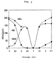
- Fig. 3 is a NOx (NO, NO 2 ) reduction characteristic explanatory view of a spiral shape discharge portion according to the present invention.
- Fig. 4A is an explanatory view showing a general exhaust gas processing apparatus having a means for processing the particle substances employing a low voltage discharge of an embodiment according to the present invention.
- Fig. 4B is a selective and all-inclusive explanatory view showing an apparatus for processing the particle substances employing a low voltage discharge according to the present invention.
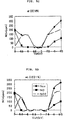
- Fig. 5A is NOx reduction characteristic view according to a discharge in an oxygen concentration of 10 % in the exhaust gas.
- Fig. 5B is NOx reduction characteristic view according to a discharge in an oxygen concentration of 15 % in the exhaust gas.
- Fig. 5C is NOx reduction characteristic view according to a discharge in an oxygen concentration of 18 % in the exhaust gas.
- Fig. 5D is NOx reduction characteristic view according to a discharge in an oxygen concentration of 21 % in the exhaust gas.
- Fig. 6 is an explanatory view showing a sensing method in a case where the reduction of NOx is controlled.
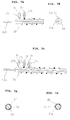
- Fig. 7A is a structure explanatory view of a discharge wire in which plural wires are combined to maintain the performance of the discharge wire.
- Fig. 7B is a side cross-sectional view of a discharge wire shown in Fig. 7A.
- Fig. 7C is an explanatory view showing a method for changing the pitch in a case in which the discharge characteristic is changed.
- Fig. 7D is an explanatory view showing an example of an insulation structure of the insulation core wire.
- Fig. 7E is an explanatory view showing another example of an insulation structure of the insulation core wire.
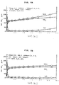
- Fig. 8A is NOx reduction characteristic view showing a discharge in which an oxygen concentration is 10 % and C 2 H 4 concentration is 1000 ppm in the exhaust gas.
- Fig. 8B is NOx reduction characteristic view showing a discharge in which an oxygen concentration is 21 % and C 2 H 4 concentration is 1000 ppm in the exhaust gas.
- Fig. 9 is an explanation view showing an example of an exhaust processing machine in which the heat retaining and the combustion sane the reaction are carried out effectively.
- Fig. 1A is an exhaust gas processing apparatus of one embodiment according to the present invention
- Fig. 1B is an exhaust gas processing apparatus of one embodiment according to the prior art.
- the features of the present invention are classified largely to two processing units, in a pre-process a processing according to a barrier discharge is carried out and in a post-process a processing using a catalyst is carried out.
- a bear discharge wire 3 is adhered closely on a surface of an insulation body and is netted with a spiral type and a cloth type as shown an example and is gotten across all over a space.
- An end portion of the discharge wire 3 is connected to a ground earth 4 and between the insulation core wire a barrier discharge is generated effectively according to a supply power control unit 11 in which a high frequency and high voltage generation means is installed in an interior portion.
- the sine wave is formed to have a pulse shape and the voltage may be formed the same from a power aspect and the voltage may be arisen.
- a sensor 10 detects the operation condition of an engine and detects directly the particle substance and NOx.
- a rotation number of the engine may be carried out using another means (not shown in figure).
- NOx exhausted from the engine etc. in particular NO and NO 2 , is decomposed completely and according to the changes of the voltage, the frequency number and the waveform, NO is decomposed completely and NOx is produced only and amount of thereof is controlled.
- the structure of the discharge wire is constituted with a very simple electric wire and an optical fiber manufacture technique, the manufacture thereof is attained with a high reliability and the cost has been very cheep.
- NO 2 is generated by detecting the amount necessary for oxidizing the particle substance in the post-process using the oxidation property gas.
- the conventional apparatus has been no control function.
- the discharge unit according to the present invention can be grasped exactly the condition of the engine and also the generation of the decomposition suited to NOx on the condition is followed in a real time.
- the catalyst processing unit in the post-process will be explained.
- the catalyst in which mainly the particle substance is decomposed completely is used in the low temperature of about 300 C.
- the comparatively low cost catalyst such as the oxide of vanadium 5 and the oxide of molibudiam and alumina or the zeolite 7 is used and NO2 is worked effectively and then the substance is decomposed completely.
- a reference numeral 1 is a frame of the machine and apparatus and a reference numeral 8 is a partition wall having a superior permeability performance for holding the catalyst.
- the removal of NO is not carried out completely and NO of 85 % is discharged from an exhaust port. This can be said that it has been the incompleteness apparatus.
- the noble metal is used mainly as the catalyst and the platinum 5b, paradigm 6b and alumina 7b is used and the processing is carried out.
- a reference numeral 1a is a frame of the machine and apparatus, and a reference numeral 8a is a partition wall having a superior permeability performance for holding the catalyst.
- FIG. 2A and Fig. 2B show the long and narrow insulation core wire which is constituted by a core wire 22a and an insulation body 2a which is made by a material having a superior ductility performance and thin and tuff material such as a ceramic and a heat resistance silicon rubber which is covered an outer skin of the core wire 22a.
- An electrode is formed by the insulation core wire and a thin and bear discharge wire 3a having a diameter of from 0.2 mm to 0.3 mm which is arranged closely to this insulation core wire.
- An insulation body 17a is used for the electric isolation when the bear wire is drawn out the outer portion of the apparatus and machine.
- the manufacture method having the high reliability performance such as the electric wire and the optical fiber is utilized and it is possible to manufacture the discharge wire having the low cost and the high performance.
- This is the material having a superior ductility performance in which the zirconium is blended to the alumina and also having superior insulation performance.
- FIG. 2C and Fig. 2D show an example in which the discharge wire 3b is arranged with a spiral shape against the insulation core wires 2b and 22b.
- a reference numeral 17 is an insulation body.
- the discharge wire 3c is assembled with a net shape and to the insulation core wires 2c and 22c the discharge wire is arranged with a cylindrical shape.
- the discharge wire has became strong and has been the high durability performance and further in addition to the conducting body, for example it is possible to net using the ceramic wire including the glass and the alumina.
- the catalyst is burdened and the ozone and the active oxygen are generated effectively.
- the particle substance is decomposed and is processed all at once. As a result, the decomposition of the exhaust gas is carried out.
- a reference numeral 17c is an insulation body.
- Fig. 3 shows one example of the characteristic of the NOx decomposition of the spiral discharge wire against the alternating current application voltage.
- NO is reduced abruptly in company with the voltage rise and is vanished completely in 6 kV and is continued zero (0) until 7.5 kV and further when the voltage is arisen the concentration is increased gradually.
- NO is zero (0) condition
- NOx is presented only NO 2 condition and between from 6.5 kV to 7.5 kV, it is changed abruptly with a V shape between from 130 ppm to zero.
- Fig. 4A shows the apparatus having the sensing function in which the particle substance is processed in the real time and further the processing waste is monitored always and is processed using the plural adsorption faces of a ceramic filter 60.
- the condition of the adhesion of the carbon system particle substance is grasped, for example, according to the change in the electric resistance.
- the power supply for the electric supply has been very low voltage such as a several voltage (V) and in the automobile etc. it can be employed the power supply of the battery and the dynamo.
- the processing of the particle substance is down simple and is processed in the real time, and further it is invited the low cost and the system having the superior durability performance is constructed.
- the lower temperature catalyst for NOx decomposition is used, for example in which alumina, the oxides of gallium, tin, and indium are burdened, only this process the harmful substance in the exhaust gas is processed.
- This catalyst processing unit is constituted with NOx processing use catalyst and is constituted with the alumina 5c, oxides of gallium 6c, tin, and indium 7c etc..
- An ammonia generation means 30 is provided in an exterior portion or in an interior portion and then an amount for necessarily process for use is supplied from a nozzle 31. It is possible to employ the plasma technique and the high pressure synthesis technique.
- the denitration system which have established from the technical aspect in the present time can be formed.
- hydrogen and nitrogen has been necessary, but hydrogen is made from the water such as the cooling water of the engine using the electrolytic process and nitrogen is taken from the air, in this time it is unnecessary to furnish the material supply.
- a final process in this figure is a discharge processing unit and this is mounted for the residual NOx processing and can be utilized as a part for the above stated ammonia generation.
- a reference numeral 2d is an insulation core wire
- a reference numeral 3d is a discharge wire
- a reference numeral 11a is a high voltage generating portion.
- a reference numeral 1b is a frame.
- Reference numerals 70 and 71 are NOx sensor and NO 2 sensor and they are installed in a suitable position in before or after the processing of NOx processing unit. They have sensed NOx processing condition in the discharge unit and adjust the voltage for necessary to carry out NOx removal and the frequency number and further control the electric energy. A control method will be explained referring to Fig. 6.
- Fig. 4B shows one example of a processing unit of the electric particle substance.
- the resistance which is accompanied with the adhesion of the particle substances between the electrodes 61a which are provided in both ends of a ceramic filter 60a is processed by a sensor detection control portion 50 and between the electrodes necessary for particle substance processing the signal is sent to a burn-up processing control portion and is processed.
- Switch portions 54 and 54a are opened or closed by the signal line 53 and the unevenness of the particle substances due to the place is gotten rid of.
- the high performance particle substance processing apparatus having the self-help function and being low cost is provided.
- a reference numeral 40a is a power supply terminal.
- Fig. 5 shows an explanation of an example in which when the diesel exhaust gas is decomposed with the high voltage discharge the decomposition of NOx is changed extremely according to the oxygen concentration in the gas.
- Fig. 5A shows a decomposition of the voltage - NOx (NO and NO 2 ) during the oxygen concentration in the exhaust gas of 10 % and in accompany with the voltage arise NO is decomposed at first and in the vicinity of the voltage of 6.5 kV it is presented the lowest and more than this value it is increased gradually.
- NO 2 is increased in an anti-proportion to the reduction of NO and is changed almost from the vicinity of 6 - 6.5 kV.
- Fig. 5B shows a decomposition of the voltage - NOx (NO and NO 2 ) during the oxygen concentration in the exhaust gas of 15 % and NO is decomposed and vanished until the vicinity of the voltage of 5.5 kV and in turn NO 2 is increased abruptly.
- NO is vanished gradually from 5.5 - 6.5 kV and has became zero (0) the zero (0) condition is continued to the voltage of 7.5 kV and more than this the generation is caused again and in accompany with the increase of the voltage it is increased.
- NO 2 is increased slightly between the voltage of 5.5 - 6.5 kV and after the highland condition is continued and is reached to a peak and after the voltage of 6.5 kV it is shifted to the reduction and in the vicinity of 7 kV it is shown the minimum value and after that is shifted to the increase. In the boundary of 7.5 kV in accompany with the increase of NO it is shifted to reduce again.
- Fig. 5C shows a decomposition of the voltage - NOx (NO and NO 2 ) during the oxygen concentration in the exhaust gas of 18 % and NO and NO 2 is vanished together with and a V curve line is appeared extremely. Between the voltage of from 6.5 kV to 7 kV, it is possible to vanish completely.
- a range of the complete vanish is spread from the voltage 5.6 kV to the voltage of 7.5 kV. Utilizing this characteristic it is possible to vanish completely NOx.
- the oxygen concentration in the exhaust gas exhausted from the diesel engine has been substantially 16 %, by the provision of the oxygen supplying means in an outer portion or the system in the apparatus and machine, the effect means for reducing NOx is constructed.
- Fig. 5D shows a decomposition of the voltage - NOx (NO and NO 2 ) during the oxygen concentration in the exhaust gas of 21 % and NOx reduction characteristic is exhibited remarkably that of the oxygen concentration of 18 %.
- Fig. 6 is an explanation view showing a control method for determining the energy necessary for NOx processing by grasping the processing conditions in NOx processing apparatus.
- the sensors are arranged in a suitable position in before and after the flow passage of the discharge element in NOx processing apparatus and the processing condition of NOx is grasped.
- the reduction decay of NOx or the increase decay of NOx are caught by the two sensors, and for example, when the reduction condition is presented from A point to B point, the energy is increased, and when from D point to C point it is changed, the energy is lowered, as a result the control is carried out surely and NOx is gotten completely rid of to remove.
- the oxygen concentration adjustment apparatus in the system is tied up.
- Fig. 7 shows an example of a new structure of the insulation discharge wire.
- Fig. 7A two discharge wires 3d and 3e which are arranged in parallel and separately are wound with a spiral shape and they are constituted by the insulation discharge wire.
- a reference numeral 22d is a conductive body of the insulation core wire and reference numerals 17d and 17e are insulation bodies of a lead wire portion of the discharge wire.
- Fig. 7B shows a side cross-sectional view of the insulation discharge wire of Fig. 7A.
- Fig. 7C shows an example in which the insulation discharge wire is constituted by placing in parallel the discharge wires 3f and 3h and by winding with a spiral shape.
- the insulation and discharge wire is constituted with a core wire conductive body 22e, insulation body 2e, and a lead wire insulation bodies 17f, 17fg and 17h.
- the discharge performance of this kind discharge insulation wire is differed extremely according to an arrangement pitch size of the discharge wire.
- the insulation body having a discharge wire diameter of 0.3 mm in a case of a pitch of 10 mm the most discharge characteristic is attained.
- the discharge characteristic is changed largely according to the pitch and the length and it is changed less than of 1/2.
- the discharge characteristic is changed according to the combination of the discharge wires and the length of the tap.
- the pitch is changed, the plural discharge wires are wound and the connection thereof and the combination are changed and further making the same polarity and selecting them the discharge characteristic is changed.
- Fig. 7D shows a cross-sectional view of the structure of the insulation body of the insulation core wire.
- a reference numeral 22f is a core conductive body and reference numerals 2f and 2g are insulation bodies.
- the insulation 2f is constituted with a substance in which to a substance an alumite processing is carries out with a net shape ceramic member and a space of this is buried with another insulation member and with a thin superior insulation performance.
- Fig. 7E shows a cross-sectional view of the thin insulation core wire having the high performance in which to the insulation core wire using the nichrome wire 22g having the high heat resistance and the high strength material.
- alumite processing is carried out after it has formed a wire member by covering the alumina 2h and to the core wire an outer portion insulation body 2i is covered.
- Fig. 8 is a graph showing the change of the characteristic in a case when the hydrocarbon is mixed with the exhaust gas.
- the oxygen concentration having the oxygen concentration 21 % shown in Fig. 5D is mixed with the hydrocarbon having 1000 ppm, it can be admitted that the remarkable reduction of NOx is not appeared.
- NO 2 is carried out stably. Namely, NO is converted to NO 2 and as the oxidizing agent it is utilized effectively for the oxidation and the removal of the particle substance.
- the concentration of the oxygen and the concentration of the hydrocarbon are controlled organically and then the processing apparatus having the stable and high performance is realized.
- Fig. 8A and Fig. 8B show NOx processing characteristics of the cases where the hydrocarbon of 1000 ppm and the oxygen concentration of 10 % and the hydrocarbon of 1000 ppm and the oxygen concentration of 21 % is mixed.
- NOx is not removed completely but it is possible to remove NOx by combing the above stated technique shown in Fig. 5 in the final process of the processing apparatus.
- Fig. 9 shows the exhaust gas apparatus in which, to reserve and not to escape the heat amount generated during the ozone generation and the corona generation according to the heat generation and the discharge when the particle substance is applied the electric power and is burned up, making the adiabatic structure with the ceramic to the outer portion of the apparatus, the inner portion of the apparatus is maintained with the high temperature as possible, it is possible to carry out the reaction and the decomposition with the small energy addition.
- a preheat portion is arranged at a vicinity of the engine exhaust port and the combustion temperature of the particle substance is reached to 650 C as possible and then the reaction promotion and the energy saving is attained.
- the above stated exhaust gas processing apparatus has been the comparative simple structure in comparison with that of the prior art apparatus and has been the epochmaking gas processing technique which enable to make the harmless performance of the harmful exhaust gas by following the operation condition of the engine etc. and is utilized all fields relating to the decomposition of the gas and the reaction.
- This apparatus is utilized effectively to the pollution measure of the automobile, the boiler and the engine and the chemical reaction promotion, the combustion promotion, and the decomposition of the harmful substance.
- the discharge portion can be manufactured from the advanced production techniques of the wire and the optical fiber and accordingly the ozone generation apparatus having the high quality, the superior production performance, and the simple structure and the low cost or the corona generating apparatus can be provided.
- the electric applying and burn-up apparatus having the low voltage and the very low cost can be applied to the adsorption and decomposition apparatus having combustible substance.
- the electric supply and burning-up apparatus having the ammonia is generated independently and when NOx denitration system is taken in the installation type film.
- the effects according to the present invention has the excellent effects as the exhaust gas post-processing apparatus such as the automobile and the boiler the performance, the cost performance and the maintenance performance can be solved at a stroke.
- the main effects are as following:
Landscapes
- Chemical & Material Sciences (AREA)
- Engineering & Computer Science (AREA)
- Chemical Kinetics & Catalysis (AREA)
- Analytical Chemistry (AREA)
- General Chemical & Material Sciences (AREA)
- Oil, Petroleum & Natural Gas (AREA)
- Combustion & Propulsion (AREA)
- Health & Medical Sciences (AREA)
- Biomedical Technology (AREA)
- Environmental & Geological Engineering (AREA)
- Toxicology (AREA)
- Mechanical Engineering (AREA)
- General Engineering & Computer Science (AREA)
- Exhaust Gas After Treatment (AREA)
- Exhaust Gas Treatment By Means Of Catalyst (AREA)
- Treating Waste Gases (AREA)
- Plasma Technology (AREA)
- Processes For Solid Components From Exhaust (AREA)
- Filtering Of Dispersed Particles In Gases (AREA)
- Physical Or Chemical Processes And Apparatus (AREA)
Applications Claiming Priority (4)
| Application Number | Priority Date | Filing Date | Title |
|---|---|---|---|
| JP2001058135 | 2001-03-02 | ||
| JP2001058135 | 2001-03-02 | ||
| JP2002020368A JP2002357119A (ja) | 2001-03-02 | 2002-01-29 | 放電現象などを用いた高効率排気ガス処理システム |
| JP2002020368 | 2002-01-29 |
Publications (3)
| Publication Number | Publication Date |
|---|---|
| EP1236497A2 true EP1236497A2 (fr) | 2002-09-04 |
| EP1236497A3 EP1236497A3 (fr) | 2003-04-02 |
| EP1236497B1 EP1236497B1 (fr) | 2007-10-31 |
Family
ID=26610505
Family Applications (1)
| Application Number | Title | Priority Date | Filing Date |
|---|---|---|---|
| EP02251418A Expired - Lifetime EP1236497B1 (fr) | 2001-03-02 | 2002-02-28 | Système de traitement de gaz d'échappement et son utilisation |
Country Status (5)
| Country | Link |
|---|---|
| US (1) | US6908596B2 (fr) |
| EP (1) | EP1236497B1 (fr) |
| JP (1) | JP2002357119A (fr) |
| KR (1) | KR100875882B1 (fr) |
| DE (1) | DE60223186T2 (fr) |
Cited By (1)
| Publication number | Priority date | Publication date | Assignee | Title |
|---|---|---|---|---|
| WO2005000450A1 (fr) | 2003-06-27 | 2005-01-06 | Ngk Insulators, Ltd. | Dispositif et procédé de traitement de gaz d'échappement |
Families Citing this family (7)
| Publication number | Priority date | Publication date | Assignee | Title |
|---|---|---|---|---|
| US7198764B2 (en) * | 2003-03-05 | 2007-04-03 | Delphi Technologies, Inc. | Gas treatment system and a method for using the same |
| JP4651470B2 (ja) * | 2005-07-14 | 2011-03-16 | 本田技研工業株式会社 | 排気ガス浄化装置 |
| KR100623665B1 (ko) * | 2005-10-10 | 2006-09-13 | 홍성모 | 물을 이용한 이산화탄소 제거 대기정화 시스템 |
| JP6122283B2 (ja) * | 2012-11-29 | 2017-04-26 | 日野自動車株式会社 | アンモニア発生装置及びそれを用いた排気浄化装置 |
| DE102014201020A1 (de) * | 2014-01-21 | 2015-07-23 | Bayerische Motoren Werke Aktiengesellschaft | Einrichtung zum Nehmen wenigstens einer gasförmigen Probe und Verfahren zum Analysieren wenigstens einer gasförmigen Probe |
| CN107551780A (zh) * | 2017-09-27 | 2018-01-09 | 成都鑫威隆机电设备有限公司 | 一种废气处理系统及其控制设备 |
| US10780395B2 (en) * | 2017-12-04 | 2020-09-22 | Ricardo Inc. | Pollutant treatment process and apparatus |
Family Cites Families (9)
| Publication number | Priority date | Publication date | Assignee | Title |
|---|---|---|---|---|
| US5263317A (en) * | 1990-05-25 | 1993-11-23 | Kabushiki Kaisha Nagao Kogyo | Exhaust gas purifying apparatus for automobile diesel engine |
| JPH06205935A (ja) * | 1992-12-25 | 1994-07-26 | Toshiba Corp | 脱硝制御装置 |
| US5807526A (en) * | 1993-11-05 | 1998-09-15 | Miljevic; Vujo | Device for removal of SO2 and NOx from flue gases by high frequency discharge by Tesla coil or other high voltage and high frequency generator |
| US5711147A (en) * | 1996-08-19 | 1998-01-27 | The Regents Of The University Of California | Plasma-assisted catalytic reduction system |
| US6038853A (en) * | 1996-08-19 | 2000-03-21 | The Regents Of The University Of California | Plasma-assisted catalytic storage reduction system |
| DE19846320C1 (de) * | 1998-10-08 | 2000-06-29 | Dickels Karl | Vorrichtung zur Abscheidung von Stickoxiden und Partikeln aus einem Gasstrom |
| GB9901413D0 (en) * | 1999-01-23 | 1999-03-10 | Aea Technology Plc | Reactor for plasma assisted gas processing |
| WO2001000525A1 (fr) * | 1999-06-29 | 2001-01-04 | Otres, Inc. | Generateur d'ozone a decharges par effet de couronne dote de conducteurs recouverts d'un isolant |
| GB9919200D0 (en) * | 1999-08-14 | 1999-10-20 | Johnson Matthey Plc | Pollution control |
-
2002
- 2002-01-29 JP JP2002020368A patent/JP2002357119A/ja active Pending
- 2002-02-28 EP EP02251418A patent/EP1236497B1/fr not_active Expired - Lifetime
- 2002-02-28 KR KR1020020011045A patent/KR100875882B1/ko not_active Expired - Fee Related
- 2002-02-28 DE DE60223186T patent/DE60223186T2/de not_active Expired - Fee Related
- 2002-03-04 US US10/086,887 patent/US6908596B2/en not_active Expired - Fee Related
Cited By (1)
| Publication number | Priority date | Publication date | Assignee | Title |
|---|---|---|---|---|
| WO2005000450A1 (fr) | 2003-06-27 | 2005-01-06 | Ngk Insulators, Ltd. | Dispositif et procédé de traitement de gaz d'échappement |
Also Published As
| Publication number | Publication date |
|---|---|
| US6908596B2 (en) | 2005-06-21 |
| DE60223186D1 (de) | 2007-12-13 |
| JP2002357119A (ja) | 2002-12-13 |
| EP1236497B1 (fr) | 2007-10-31 |
| EP1236497A3 (fr) | 2003-04-02 |
| KR100875882B1 (ko) | 2008-12-24 |
| DE60223186T2 (de) | 2008-08-14 |
| KR20020070885A (ko) | 2002-09-11 |
| US20030031609A1 (en) | 2003-02-13 |
Similar Documents
| Publication | Publication Date | Title |
|---|---|---|
| KR101114167B1 (ko) | 배기 가스 정화용 촉매의 재생 장치 및 재생 방법 | |
| US20010001435A1 (en) | Apparatus and method for removing nox and other pollutants from gas streams using a plasma assisted catalyst | |
| CN100365251C (zh) | 排气净化装置 | |
| EP1703540B1 (fr) | Réacteur à plasma | |
| US20060207428A1 (en) | Gas purifying apparatus | |
| EP1236497A2 (fr) | Système de traitement de gaz d'échappement | |
| US6886328B2 (en) | Exhaust gas processing system | |
| US20090205315A1 (en) | Apparatus and Method for PM Purification | |
| JPH0866621A (ja) | 窒素酸化物の除去方法 | |
| US20040234430A1 (en) | Exhaust gas purifying apparatus and method of using the same | |
| US7181903B2 (en) | Exhaust gas purifying apparatus and method of using the same | |
| JP2006132483A (ja) | 排気浄化装置及び排気浄化方法並びに制御方法 | |
| WO2005083241A1 (fr) | Source d'energie de reacteur plasma, reacteur a plasma, dispositif de purification des gaz d'echappement et procede de purification des gaz d'echappement | |
| JP2002256851A (ja) | 内燃機関の排気浄化装置 | |
| JP2004204739A (ja) | 排ガス浄化システムおよび排ガス浄化方法 | |
| KR100347593B1 (ko) | 내연기관의 배출가스 정화장치 | |
| JP4591164B2 (ja) | 排ガス浄化方法及び排ガス浄化装置 | |
| JPS63268911A (ja) | エンジンの排気浄化装置 | |
| JP2005344688A (ja) | 内燃機関の排気浄化装置 | |
| JP2007009839A (ja) | 排ガス浄化装置 | |
| KR200374504Y1 (ko) | 촉매박막형 고전압 건식 방전필터를 갖는 자동차배기가스 정화장치 | |
| JPH0849527A (ja) | 排気ガス浄化用触媒装置 | |
| JP2007016635A (ja) | 内燃機関の排気浄化装置 | |
| KR100404417B1 (ko) | 디젤엔진 배출가스에서 매연과 질소산화물을 제거하기위한 디젤분진필터/플라즈마/촉매 시스템 | |
| JP2004263636A (ja) | 排気ガス浄化装置 |
Legal Events
| Date | Code | Title | Description |
|---|---|---|---|
| PUAI | Public reference made under article 153(3) epc to a published international application that has entered the european phase |
Free format text: ORIGINAL CODE: 0009012 |
|
| AK | Designated contracting states |
Kind code of ref document: A2 Designated state(s): AT BE CH CY DE DK ES FI FR GB GR IE IT LI LU MC NL PT SE TR |
|
| AX | Request for extension of the european patent |
Free format text: AL;LT;LV;MK;RO;SI |
|
| PUAL | Search report despatched |
Free format text: ORIGINAL CODE: 0009013 |
|
| AK | Designated contracting states |
Designated state(s): AT BE CH CY DE DK ES FI FR GB GR IE IT LI LU MC NL PT SE TR Kind code of ref document: A3 Designated state(s): AT BE CH CY DE DK ES FI FR GB GR IE IT LI LU MC NL PT SE TR |
|
| AX | Request for extension of the european patent |
Extension state: AL LT LV MK RO SI |
|
| 17P | Request for examination filed |
Effective date: 20030917 |
|
| AKX | Designation fees paid |
Designated state(s): DE FR GB |
|
| 17Q | First examination report despatched |
Effective date: 20040226 |
|
| GRAP | Despatch of communication of intention to grant a patent |
Free format text: ORIGINAL CODE: EPIDOSNIGR1 |
|
| RIC1 | Information provided on ipc code assigned before grant |
Ipc: B01D 53/32 20060101AFI20070302BHEP Ipc: F01N 3/08 20060101ALI20070302BHEP Ipc: B01D 53/94 20060101ALI20070302BHEP |
|
| RTI1 | Title (correction) |
Free format text: EXHAUST GAS PROCESSING SYSTEM AND ITS USE |
|
| GRAS | Grant fee paid |
Free format text: ORIGINAL CODE: EPIDOSNIGR3 |
|
| GRAA | (expected) grant |
Free format text: ORIGINAL CODE: 0009210 |
|
| AK | Designated contracting states |
Kind code of ref document: B1 Designated state(s): DE FR GB |
|
| REG | Reference to a national code |
Ref country code: GB Ref legal event code: FG4D |
|
| REF | Corresponds to: |
Ref document number: 60223186 Country of ref document: DE Date of ref document: 20071213 Kind code of ref document: P |
|
| ET | Fr: translation filed | ||
| PLBE | No opposition filed within time limit |
Free format text: ORIGINAL CODE: 0009261 |
|
| STAA | Information on the status of an ep patent application or granted ep patent |
Free format text: STATUS: NO OPPOSITION FILED WITHIN TIME LIMIT |
|
| 26N | No opposition filed |
Effective date: 20080801 |
|
| PGFP | Annual fee paid to national office [announced via postgrant information from national office to epo] |
Ref country code: DE Payment date: 20090225 Year of fee payment: 8 |
|
| PGFP | Annual fee paid to national office [announced via postgrant information from national office to epo] |
Ref country code: GB Payment date: 20090220 Year of fee payment: 8 |
|
| PGFP | Annual fee paid to national office [announced via postgrant information from national office to epo] |
Ref country code: FR Payment date: 20090224 Year of fee payment: 8 |
|
| GBPC | Gb: european patent ceased through non-payment of renewal fee |
Effective date: 20100228 |
|
| REG | Reference to a national code |
Ref country code: FR Ref legal event code: ST Effective date: 20101029 |
|
| PG25 | Lapsed in a contracting state [announced via postgrant information from national office to epo] |
Ref country code: FR Free format text: LAPSE BECAUSE OF NON-PAYMENT OF DUE FEES Effective date: 20100301 |
|
| PG25 | Lapsed in a contracting state [announced via postgrant information from national office to epo] |
Ref country code: DE Free format text: LAPSE BECAUSE OF NON-PAYMENT OF DUE FEES Effective date: 20100901 |
|
| PG25 | Lapsed in a contracting state [announced via postgrant information from national office to epo] |
Ref country code: GB Free format text: LAPSE BECAUSE OF NON-PAYMENT OF DUE FEES Effective date: 20100228 |