EP1236541A2 - Rotationswerkzeug für Oberflächenbearbeitung und Verfahren zu seiner Herstellung - Google Patents
Rotationswerkzeug für Oberflächenbearbeitung und Verfahren zu seiner Herstellung Download PDFInfo
- Publication number
- EP1236541A2 EP1236541A2 EP02004455A EP02004455A EP1236541A2 EP 1236541 A2 EP1236541 A2 EP 1236541A2 EP 02004455 A EP02004455 A EP 02004455A EP 02004455 A EP02004455 A EP 02004455A EP 1236541 A2 EP1236541 A2 EP 1236541A2
- Authority
- EP
- European Patent Office
- Prior art keywords
- holding element
- tool body
- dowel pin
- holding
- pin
- Prior art date
- Legal status (The legal status is an assumption and is not a legal conclusion. Google has not performed a legal analysis and makes no representation as to the accuracy of the status listed.)
- Withdrawn
Links
Images

Classifications
-
- B—PERFORMING OPERATIONS; TRANSPORTING
- B24—GRINDING; POLISHING
- B24D—TOOLS FOR GRINDING, BUFFING OR SHARPENING
- B24D13/00—Wheels having flexibly-acting working parts, e.g. buffing wheels; Mountings therefor
- B24D13/02—Wheels having flexibly-acting working parts, e.g. buffing wheels; Mountings therefor acting by their periphery
- B24D13/08—Wheels having flexibly-acting working parts, e.g. buffing wheels; Mountings therefor acting by their periphery comprising annular or circular sheets packed side by side
-
- Y—GENERAL TAGGING OF NEW TECHNOLOGICAL DEVELOPMENTS; GENERAL TAGGING OF CROSS-SECTIONAL TECHNOLOGIES SPANNING OVER SEVERAL SECTIONS OF THE IPC; TECHNICAL SUBJECTS COVERED BY FORMER USPC CROSS-REFERENCE ART COLLECTIONS [XRACs] AND DIGESTS
- Y10—TECHNICAL SUBJECTS COVERED BY FORMER USPC
- Y10T—TECHNICAL SUBJECTS COVERED BY FORMER US CLASSIFICATION
- Y10T29/00—Metal working
- Y10T29/49—Method of mechanical manufacture
- Y10T29/49826—Assembling or joining
Definitions
- the invention relates to a rotary tool for surface processing and a process for its manufacture.
- the Rotary tool has a roll pin for clamping in a rotationally drivable tensioning device and at least one around Arranged dowel pin and attached to the dowel pin Tool body on.
- Rotary tools of this type in which the surface treatment predominantly with the radial outer sides of the tool body is carried out in a wide range of areas from Deburring used until polishing.
- Car paints are sanded or surfaces polished or like.
- the rotary tool can, for example, be such be formed in a chuck of a drill clamped and driven by these in rotation.
- an adhesive for example Cast resin to use.
- the tool body has a center through hole, whose diameter is usually clear is larger than the outside diameter of the dowel pin.
- For fixing of the tool body becomes the space between the roll pin and the wall of the tool body bore with adhesive poured out.
- the disadvantage here is that this method is very is time-consuming because the adhesive needs a certain drying time.
- the adhesive is relatively expensive and not exactly environmentally friendly. In addition, it happens again and again that when pouring glue runs next to it and pollutes the workplace, so that it afterwards must be cleaned.
- the object of the invention is to provide a manufacturing method for Provide rotary tools that are fast, flexible and inexpensive manufacture of the rotary tools allowed, as well as a Rotating tool for surface finishing to create that simple and is inexpensive to manufacture.
- a first holding element Holding device attached to the dowel pin. After that the tool body is pushed on until an axial end of the Tool body rests on the first holding element. Then one second holding element of the holding device on the dowel pin up to postponed a freely definable holding position. In this Holding position is the second holding element in engagement with the other axial end of the tool body. In the stop position, the second Holding element fixed to the roll pin.
- the rotary tool can thus be moved by moving the second Holding element on very different, continuously adjustable Tool body heights can be set.
- rotary tools according to the invention can for Tool bodies of different types and heights always the same Dowel pins and the same holding elements are used. It will only the relative position of the holding elements to each other changed or appropriately set. Compared to the rotary tool, the one Save dowel pin with shoulder and threaded section So the stocking of differently designed dowel pins.
- a surface treatment method in the sense of the registration all suitable ones that can be carried out with a rotary tool Processes such as polishing, grinding, deburring, Gloss processing or the like understood.
- the rotary tool can, for example, as a sanding mob, shiny mob or the like be trained.
- the rotating Drivable clamping device can be a chuck, for example Drill, grinder or flexible shaft.
- the dowel pin of the rotary tool has a clamping section, which is used for clamping in the clamping device.
- the Tool body is preferably rotationally symmetrical about one Tool carrier section of the dowel pin arranged around that there are no imbalances when operating the rotary tool, due to the possibly undesired grinding or polishing grooves on machined workpiece arise.
- materials for the Tool bodies are all for the aforementioned surface treatment processes suitable materials can be used.
- Tool body made of flexible materials are usually called mobs or stoppers.
- inflexible or largely hard materials such as for example wood or the like for corresponding Use surface processing tasks.
- the attachment of the second holding element to the dowel pin can done in different ways. For example, it is possible that glue second holding element to the dowel pin or to weld. Also an attachment by means of fasteners, such as Screws, clamps, rivets or the like is conceivable. Especially however, it is preferred to have the second holding element without a separate one Fix fasteners on the dowel pin. This is preferably done exclusively via frictional connection between the holding element and the Dowel pin. As a method for this, z. B. a pressing process at with the retaining element, which initially sits loosely on the dowel pin a press is pressed onto the roll pin. The attachment of the second holding element in the holding position can also be by means of ashrinking process.
- the second is particularly preferably pushed on Holding element in the holding position under the influence of a Feed force and overcoming friction between the second holding element and the roll pin.
- the second holding element is So dimensioned so that it automatically in the absence of external forces is non-positively or frictionally fixed to the dowel pin. To The second holding element can then remove the feed force automatically in the holding position on the dowel pin be held.
- the holding elements preferably each have a recess, in particular a central opening on it enables the holding elements to be threaded onto the dowel pin.
- the diameter of the central opening is preferably at least that second holding element slightly smaller than the outer dimensions, especially the diameter of the dowel pin.
- the second Holding element is therefore preferably by means of a press fit on the roll pin attached.
- the dowel pin preferably has substantially over its entire length is uniform, preferably circular Cross-section.
- Such cylindrical pins without shoulders, projections or the like are particularly inexpensive in large quantities and practically any length available.
- non-circular cross-sections, z. B. Hexagonal cross-sections are possible. These make it easier to prevent rotation the holding elements on the dowel pin.
- the second holding element is preferably so far in the direction the first retaining element pushed onto the roll pin that the Tool body axially at least in an interior area near the dowel pin is pressed together. This is especially true with multi-part several existing stacked disks Tool bodies an advantage because it prevents a space remains between the individual panes, and the Tool body may start to "flutter" in operation.
- the Tool body can possibly be reduced to less than 80%, in particular up to less than 50% of the axial length of a force-free tool body are pressed together.
- the tool body only secured against rotation on the dowel pin by the holding elements attached.
- axial Projections on the holding elements to be formed Penetration into the material of the tool body are formed.
- the axial projections can take the form of claws, Have spikes or tips.
- the axial Projections a self-cutting shape, for example the shape have a tip, so that when pushing on the retaining elements Protrusion penetrates into the material of the tool body.
- the axial Protrusions are preferably in one piece with the holding elements trained and uniform, in particular rotationally symmetrical the holding elements arranged.
- the axial projections can for example by bending protruding ones Sections of the holding elements are made.
- the invention comprises a rotary tool with the Features of independent claim 6.
- the rotary tool is characterized in that the Holding device a first holding element attachable to the roll pin for engagement at an axial end of the tool body and a freely or continuously displaceable along the dowel pin and in one Holding position fixable second holding element for engagement with the other has axial end of the tool body.
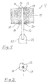
- FIG 1 shows an embodiment of an inventive Rotary tool 11.
- the rotary tool 11 includes one Dowel pin 12, a holding device with two attachable to the dowel pin Holding elements 13, 14 and one between the holding elements 13, 14 clamped tool body 15.
- the circular cylindrical dowel pin 12 is made from a blank Cut to length to the desired length. Suitable as a material especially steel, especially stainless steel.
- the roll pin 12 has one circular diameter, typically on the order of about 0.5 to 3.0 cm.
- the length of the in the embodiment dowel pin 12 shown is approximately 9.0 to 10.0 cm. smaller and larger diameters and lengths are depending on the application quite possible.
- the roll pin 12 has over its entire length a uniform cross-section.
- the first holding element 13 is located directly at one end 16 of the dowel pin 12.
- the top 17 of the first holding element 13 and the end of the dowel pin 12 form a common flush Graduation.
- the second holding element 14 is along at any point the dowel pin 12 attachable. In the described embodiment the second holding element is approximately in the middle of the Spring pin 12.
- the two are one piece Holding elements designed in the manner of a paddle wheel. You own in scope at regular intervals four in the manner of Blade-shaped axial projections 18.
- the axial projections 18 have the shape of pointed prongs in the longitudinal direction, making them relative can easily penetrate into the tool body 15.
- the Holding elements 13, 14 also each have a sleeve-shaped Middle section 20 which is in direct contact with the roll pin 12 and forms a central, cylindrical passage opening for the dowel pin.
- the holding elements 13, 14 can be easily punched out be made from a piece of sheet metal.
- the axial projections 18 can then be turned 90 ° using a suitable tool be bent.
- the tool body 15 can all for a wide variety of surface processing methods such as grinding, polishing, deburring or the like have suitable shapes. Are suitable as materials flexible, inflexible, hard or soft materials, e.g. fleece, Felts, synthetic fibers, foams, wood or the like.
- the Tool body 15 is rotationally symmetrical about dowel pin 12 arranged around. It can be made in one piece, such as in Figure 1 consist, or consist of several layers, for example several workpiece material disks, as shown in Figure 4 or 5.
- the tool body 15 shown in FIG. 1, for example, is in one piece and is made of foam.
- a clamping end 21 of the dowel pin 12, which is connected to the first holding element 13 provided end 16 is opposite, in a clamping device 22nd plugged.
- the tensioning device can be as described in FIG Shown embodiment, a chuck of a drill his.
- FIGs 3 to 5 is the manufacturing process of a rotary tool shown.
- a cut dowel pin pushed onto the first holding element 13. It is particularly advantageous in the method according to the invention that the Length and the design of the dowel pin 12 completely independent of the tool body height can be. So it can be used to manufacture different rotary tools each have the same "standard" spring pins 12 can be used.
- the diameter of the dowel pin 12 is larger than that Inner diameter of the sleeve-shaped central section of the first Holding element 13. When the feed force is removed by the press thus forms between the first holding element and the roll pin a press fit. If necessary, with radial pressing force be pressed.
- the tool body 15 threaded or attached.
- the tool body consists of several abrasive fleece discs that stacked on top of each other.
- the individual Tool body washers have a center hole for threading on the Lighten the spring pin.
- this threading can also be done by piercing the Duck pin through the tool body material.
- the Material discs are on the first holding element 13 against axial Moving fixed in the threading direction.
- the axial projections 18 of the first holding element 13 press at least into the nearest discs.
- the second Holding element 14 pushed on.
- the holding element becomes similar how the spring pin in the first step in a z. B. hydraulic operated press clamped and with feed force in his final stopping position pushed.
- the inside diameter of the is sleeve-shaped central section 20 of the second holding element 14 smaller than the diameter of the dowel pin 12. This is a Displacement along the dowel pin only by overcoming strong frictional forces possible.
- a press fit is formed automatically between the second holding element and the dowel pin 12. So they are not special Fasteners or measures such as screws, welding, Gluing, pressing or the like necessary to ensure a tight fit to ensure the second holding element on the roll pin.
- the second holding element 14 at any position along the Spring pin can be attached.
- the layers of material are divided into one
- the interior of the spring pin is very strongly compressed. In this The range is the axial spacing of the holding elements certain center height only approx. 70 to 80% or less of the stack height of a stack of disks not compressed.
- the outer contour the tool body becomes barrel-shaped.
- the tool body is at least in one Inner area near the dowel pin pressed together very strongly axially.
- the axial projections 18 of the second holding element 14 also penetrate into the tool body and secure together with the axial projections 18 of the first holding element 13 against the tool body Twist relative to the dowel pin 12 and relative to the two Holding elements 13, 14.
Landscapes
- Engineering & Computer Science (AREA)
- Mechanical Engineering (AREA)
- Polishing Bodies And Polishing Tools (AREA)
Abstract
Description
Claims (12)
- Verfahren zur Herstellung eines Rotationswerkzeuges für Oberflächenbearbeitung, insbesondere eines Schleif- oder Poliermobs, wobei das Rotationswerkzeug einen Spannstift zur Einspannung in eine rotierend antreibbare Spanneinrichtung und mindestens einen um den Spannstift herum angeordneten und an dem Spannstift befestigten Werkzeugkörper aufweist, das Verfahren mit folgenden Schritten:Befestigung eines ersten Halteelementes einer Haltevorrichtung an dem Spannstift;Aufschieben des Werkzeugkörpers auf den Spannstift bis zur Anlage eines axialen Endes des Werkzeugkörpers an dem ersten Halteelement;Aufschieben eines zweiten Halteelementes der Haltevorrichtung auf den Spannstift bis zu einer frei vorgebbaren Halteposition, in der das zweite Halteelement in Eingriff mit dem anderen axialen Ende des Werkzeugkörpers steht;Fixierung des zweiten Halteelementes an den Spannstift in der Halteposition.
- Verfahren nach Anspruch 1, dadurch gekennzeichnet, dass die Fixierung des zweiten Halteelementes an dem Spannstift ohne gesonderte Befestigungsmittel im wesentlichen über Kraftschluss zwischen Halteelement und Spannstift erfolgt.
- Verfahren nach Anspruch 1 oder 2, dadurch gekennzeichnet, dass das Aufschieben des zweiten Halteelementes in die Halteposition unter Einwirkung einer Vorschubkraft und unter Überwindung von Reibung zwischen dem zweiten Halteelement und dem Spannstift erfolgt und dass nach Wegnahme der Vorschubkraft das zweite Halteelement selbsttätig in der Halteposition an dem Spannstift kraftschlüssig festgehalten wird.
- Verfahren nach einem der vorhergehenden Ansprüche, dadurch gekennzeichnet, dass das zweite Halteelement so weit in Richtung des ersten Haltelementes auf den Spannstift aufgeschoben wird, dass der Werkzeugkörper zumindest in einem spannstiftnahen Innenbereich axial zusammengepreßt wird, vorzugsweise auf weniger als 80 %, insbesondere weniger als 50 % der axialen Länge eines kräftefreien Werkzeugkörpers.
- Verfahren nach einem der vorhergehenden Ansprüche, dadurch gekennzeichnet, dass der Werkzeugkörper ausschließlich durch die Haltelemente verdrehgesichert am Spannstift befestigt wird.
- Rotationswerkzeug für Oberflächenbearbeitung, insbesondere Schleif- oder Poliermob, mit einem Spannstift (12) zum Einspannen in eine rotierend antreibbare Spanneinrichtung (22) und mit einem Werkzeugkörper, der den Spannstift umgibt und mittels einer Halteeinrichtung am Spannstift (12) befestigt ist, wobei die Haltevorrichtung ein am Spannstift befestigbares erstes Halteelement (13) zum Eingriff an einem axialen Ende des Werkzeugkörpers (15) und ein entlang des Spannstiftes frei verschiebbares und in einer Halteposition fixierbares zweites Halteelement (14) zum Eingriff am anderen axialen Ende des Werkzeugkörpers aufweist.
- Rotationswerkzeug nach Anspruch 6, dadurch gekennzeichnet, dass mindestens eines der Halteelemente, insbesondere das zweite Halteelement (14), eine Durchgangsöffnung für den Spannstift hat, die derart zur Erzeugung eines Presssitzes zwischen Halteelement (14) und Spannstift (12) dimensioniert ist, dass das Halteelement mittels einer axial wirksamen Vorschubkraft unter Überwindung von Reibung entlang dem Spannstift verschiebbar und bei Wegnahme der Vorschubkraft selbsttätig kraftschlüssig am Spannstift fixierbar ist.
- Rotationswerkzeug nach Anspruch 6 oder 7, dadurch gekennzeichnet, dass der Werkzeugkörper (15) zumindest in einem spannstiftnahen Innenbereich aus einem zusammenpreßbaren Material besteht, wobei vorzugsweise der Werkzeugkörper mittels der Halteelemente (13, 14) zumindest in dem spannstiftnahen Innenbereich derart zusammengepreßt ist, dass der Abstand zwischen dem Halteelement wesentlich kleiner ist als die axiale Höhe des kräftefreien Werkzeugkörpers.
- Rotationswerkzeug nach Anspruch 8, dadurch gekennzeichnet, dass der axiale Abstand zwischen den Halteelementen (13, 14) weniger als 80 %, insbesondere weniger als 50 % der axialen Höhe eines kräftefreien Werkzeugkörpers (15) beträgt.
- Rotationswerkzeug nach einem der Ansprüche 6 bis 9, dadurch gekennzeichnet, dass der Werkzeugkörper (15) einen Stapel aus mehreren axial aufeinander liegenden Werkzeugmaterialscheiben aufweist, wobei die Werkzeugmaterialscheiben vorzugsweise im wesentlichen gleich dimensioniert sind und/oder aus dem gleichen Werkzeugmaterial bestehen.
- Rotationswerkzeug nach einem der Ansprüche 6 bis 10, dadurch gekennzeichnet, dass der Spannstift (12) im wesentlichen über seine gesamte Länge einen einheitlichen Querschnitt, vorzugsweise einen kreisförmigen Querschnitt aufweist.
- Rotationswerkzeug nach einem der Ansprüche 6 bis 11, dadurch gekennzeichnet, dass das erste Halteelement (13) und/oder das zweite Halteelement (14) Einrichtungen zur Verdrehsicherung des Werkzeugkörpers am Spannstift aufweist, vorzugsweise in Form axialer Vorsprünge (18), die zum Eindringen in das Material des Werkzeugkörpers ausgebildet sind.
Applications Claiming Priority (2)
| Application Number | Priority Date | Filing Date | Title |
|---|---|---|---|
| DE10110739A DE10110739A1 (de) | 2001-03-02 | 2001-03-02 | Rotationswerkzeug für Oberflächenbearbeitung und Verfahren zu seiner Herstellung |
| DE10110739 | 2001-03-02 |
Publications (2)
| Publication Number | Publication Date |
|---|---|
| EP1236541A2 true EP1236541A2 (de) | 2002-09-04 |
| EP1236541A3 EP1236541A3 (de) | 2003-11-05 |
Family
ID=7676470
Family Applications (1)
| Application Number | Title | Priority Date | Filing Date |
|---|---|---|---|
| EP02004455A Withdrawn EP1236541A3 (de) | 2001-03-02 | 2002-02-27 | Rotationswerkzeug für Oberflächenbearbeitung und Verfahren zu seiner Herstellung |
Country Status (3)
| Country | Link |
|---|---|
| US (1) | US20030000062A1 (de) |
| EP (1) | EP1236541A3 (de) |
| DE (1) | DE10110739A1 (de) |
Families Citing this family (3)
| Publication number | Priority date | Publication date | Assignee | Title |
|---|---|---|---|---|
| DE10321445B4 (de) * | 2003-05-13 | 2006-10-19 | Gerd Eisenblätter Gmbh | Walzenförmiges Schleifwerkzeug, insbesondere für eine Handarbeitsmaschine |
| RU2268137C1 (ru) * | 2004-06-21 | 2006-01-20 | Общество с ограниченной ответственностью "Торговый дом "Абразивные заводы Урала" | Способ прессования абразивного инструмента |
| US8154389B2 (en) * | 2007-03-15 | 2012-04-10 | Endotronix, Inc. | Wireless sensor reader |
Family Cites Families (3)
| Publication number | Priority date | Publication date | Assignee | Title |
|---|---|---|---|---|
| BE669070A (de) * | ||||
| DE19636474C2 (de) * | 1996-09-07 | 1997-09-04 | Rainer Dipl Phys Kleinschmidt | Verformbares Schleifwerkzeug |
| DE29804213U1 (de) * | 1998-03-10 | 1998-05-14 | August Rüggeberg GmbH & Co., 51709 Marienheide | Drehantreibbares Schleif-, Reinigungs- oder Polier-Werkzeug |
-
2001
- 2001-03-02 DE DE10110739A patent/DE10110739A1/de not_active Withdrawn
-
2002
- 2002-02-27 EP EP02004455A patent/EP1236541A3/de not_active Withdrawn
- 2002-03-01 US US10/087,575 patent/US20030000062A1/en not_active Abandoned
Also Published As
| Publication number | Publication date |
|---|---|
| EP1236541A3 (de) | 2003-11-05 |
| US20030000062A1 (en) | 2003-01-02 |
| DE10110739A1 (de) | 2002-09-05 |
Similar Documents
| Publication | Publication Date | Title |
|---|---|---|
| EP0273259A1 (de) | Spannvorrichtung für insbesondere zahnärztliche Werkzeuge | |
| DE3605569A1 (de) | Schluesselloses bohrfutter sowie verfahren zur herstellung von schluessellosen bohrfuttern | |
| DE102008045620A1 (de) | Spanneinrichtung | |
| EP2747922B1 (de) | Vorrichtung und verfahren zum spannen eines bauteils an einem rotierenden maschinenteil | |
| EP1620219A1 (de) | Ausbohrwerkzeug | |
| EP1528965A1 (de) | Werkzeug zur spanenden bearbeitung | |
| EP0286837A1 (de) | Messereinsatz | |
| DE69008758T2 (de) | Werkzeugkoppelung zwischen einem Werkzeughalter und einer Maschinenspindel. | |
| DE69809789T2 (de) | Schärfvorrichtung | |
| DE3614501C2 (de) | ||
| EP0962283A1 (de) | Kraftgetriebenes Handwerkzeug | |
| DE602006000263T2 (de) | Werkzeugspannfutter für eine drehende Maschine | |
| DE804880C (de) | Messerkopf fuer Werkzeugmaschinen | |
| EP1236541A2 (de) | Rotationswerkzeug für Oberflächenbearbeitung und Verfahren zu seiner Herstellung | |
| EP0693347A2 (de) | Eintreibgerät für Befestigungsmittel | |
| DE2112092A1 (de) | Werkzeughalter | |
| EP0972613A1 (de) | Mitnahmevorrichtung für eine Werkzeugmaschine | |
| EP0804986B1 (de) | Schneidelement | |
| DE20012746U1 (de) | Schleifwerkzeug | |
| DE3220363C2 (de) | Fräsmesserkopf für Schruppbearbeitung | |
| DE3517147A1 (de) | Werkzeug zum entgraten von bohrungsraendern | |
| DE2158779A1 (de) | Nachstellbare Maschinenreibahle | |
| DE3511580A1 (de) | Werkzeug-spannvorrichtung | |
| EP3124176A1 (de) | Schleifwerkzeug mit formprofil für ein oszillierendes schleifgerät | |
| DE7032666U (de) | Werkzeugtraeger fuer voreingestellte werkzeuge. |
Legal Events
| Date | Code | Title | Description |
|---|---|---|---|
| PUAI | Public reference made under article 153(3) epc to a published international application that has entered the european phase |
Free format text: ORIGINAL CODE: 0009012 |
|
| AK | Designated contracting states |
Kind code of ref document: A2 Designated state(s): AT BE CH CY DE DK ES FI FR GB GR IE IT LI LU MC NL PT SE TR |
|
| AX | Request for extension of the european patent |
Free format text: AL;LT;LV;MK;RO;SI |
|
| PUAL | Search report despatched |
Free format text: ORIGINAL CODE: 0009013 |
|
| AK | Designated contracting states |
Kind code of ref document: A3 Designated state(s): AT BE CH CY DE DK ES FI FR GB GR IE IT LI LU MC NL PT SE TR |
|
| AX | Request for extension of the european patent |
Extension state: AL LT LV MK RO SI |
|
| RIC1 | Information provided on ipc code assigned before grant |
Ipc: 7B 24D 13/20 B Ipc: 7B 24D 13/08 A |
|
| AKX | Designation fees paid | ||
| REG | Reference to a national code |
Ref country code: DE Ref legal event code: 8566 |
|
| STAA | Information on the status of an ep patent application or granted ep patent |
Free format text: STATUS: THE APPLICATION IS DEEMED TO BE WITHDRAWN |
|
| 18D | Application deemed to be withdrawn |
Effective date: 20040506 |