EP1236589A2 - Verbesserte Vorrichtung zum Montieren und Abmontieren von "system pax"- Leerlaufreifen und ähnliche - Google Patents
Verbesserte Vorrichtung zum Montieren und Abmontieren von "system pax"- Leerlaufreifen und ähnliche Download PDFInfo
- Publication number
- EP1236589A2 EP1236589A2 EP02075247A EP02075247A EP1236589A2 EP 1236589 A2 EP1236589 A2 EP 1236589A2 EP 02075247 A EP02075247 A EP 02075247A EP 02075247 A EP02075247 A EP 02075247A EP 1236589 A2 EP1236589 A2 EP 1236589A2
- Authority
- EP
- European Patent Office
- Prior art keywords
- implement
- tyre
- wheel rim
- support device
- bead
- Prior art date
- Legal status (The legal status is an assumption and is not a legal conclusion. Google has not performed a legal analysis and makes no representation as to the accuracy of the status listed.)
- Withdrawn
Links
- 239000011324 bead Substances 0.000 claims abstract description 42
- 239000013536 elastomeric material Substances 0.000 description 3
- 230000014759 maintenance of location Effects 0.000 description 3
- 238000003780 insertion Methods 0.000 description 1
- 230000037431 insertion Effects 0.000 description 1
Images




Classifications
-
- B—PERFORMING OPERATIONS; TRANSPORTING
- B60—VEHICLES IN GENERAL
- B60C—VEHICLE TYRES; TYRE INFLATION; TYRE CHANGING; CONNECTING VALVES TO INFLATABLE ELASTIC BODIES IN GENERAL; DEVICES OR ARRANGEMENTS RELATED TO TYRES
- B60C25/00—Apparatus or tools adapted for mounting, removing or inspecting tyres
- B60C25/01—Apparatus or tools adapted for mounting, removing or inspecting tyres for removing tyres from or mounting tyres on wheels
- B60C25/05—Machines
- B60C25/053—Support of wheel parts during machine operation
- B60C25/0545—Support of wheel parts during machine operation with rotary motion of tool or tyre support, e.g. turntables
-
- B—PERFORMING OPERATIONS; TRANSPORTING
- B60—VEHICLES IN GENERAL
- B60C—VEHICLE TYRES; TYRE INFLATION; TYRE CHANGING; CONNECTING VALVES TO INFLATABLE ELASTIC BODIES IN GENERAL; DEVICES OR ARRANGEMENTS RELATED TO TYRES
- B60C25/00—Apparatus or tools adapted for mounting, removing or inspecting tyres
- B60C25/01—Apparatus or tools adapted for mounting, removing or inspecting tyres for removing tyres from or mounting tyres on wheels
- B60C25/02—Tyre levers or the like, e.g. hand-held
- B60C25/04—Tyre levers or the like, e.g. hand-held pivotal about the wheel axis, or movable along the rim edge, e.g. rollable
-
- B—PERFORMING OPERATIONS; TRANSPORTING
- B60—VEHICLES IN GENERAL
- B60C—VEHICLE TYRES; TYRE INFLATION; TYRE CHANGING; CONNECTING VALVES TO INFLATABLE ELASTIC BODIES IN GENERAL; DEVICES OR ARRANGEMENTS RELATED TO TYRES
- B60C25/00—Apparatus or tools adapted for mounting, removing or inspecting tyres
- B60C25/01—Apparatus or tools adapted for mounting, removing or inspecting tyres for removing tyres from or mounting tyres on wheels
- B60C25/05—Machines
- B60C25/132—Machines for removing and mounting tyres
- B60C25/135—Machines for removing and mounting tyres having a tyre support or a tool, movable along wheel axis
- B60C25/138—Machines for removing and mounting tyres having a tyre support or a tool, movable along wheel axis with rotary motion of tool or tyre support
Definitions
- This invention relates to a implement intended to be associated with a usual tyre removal machine to enable the operator to mount onto and demount from a respective wheel rim a new type of self-supporting pneumatic tyre, such as that produced by the firm Michelin and known as "System Pax".
- the self-supporting tyres of System Pax type and the like enable the vehicle to travel with safety even when the inflation pressure assumes a very low value, as happens in the case of a puncture.
- said tyres essentially comprise a relatively rigid ring of elastomeric material, which is inserted into the well of the wheel rim and rests against an annular projection thereon.
- both the tyre and the wheel rim are formed with particular profiles.
- the tyre beads have different diameters, with the result that the wheel rim is non-symmetrical about a plane perpendicular to its axis, and presents seats for receiving the different-diameter beads. Moreover, to prevent the tyre beads escaping from the bead retaining flanges on the wheel rim when the vehicle travels with a punctured tyre, the profile of the tyre bead and of the matching seat present in the wheel rim are of a particular design.
- said implement comprises a wheel rim support device to be associated with the self-centering unit of the tyre removal machine.
- Said support device is composed of a disc which is gripped by the jaws with which the self-centering unit of the tyre removal machine is provided, and from which there rises an upperly threaded vertical shaft on which a cylindrical member is mounted, against which the wheel rim hub rests when the threaded shaft has been inserted into the central hole of the hub.
- the wheel rim is locked by means of known type, namely a centering cone and a quick-action locking nut.
- the aforesaid implement also comprises a roller of horizontal axis the purpose of which, during the mounting of the tyre onto the wheel rim, is to press against the side-wall of the tyre while the wheel rim is rotating, in order to facilitate the mounting of the tyre and of the toroidal ring onto the wheel rim.
- the tyre is mounted by the following operations:
- the larger-diameter bead is extracted to the outside of the wheel rim by the operator using a suitable lever which he inserts into the well of the wheel rim between the bead and the well.
- the known implement has proved suitable for the purpose if operating on wheels having a diameter not exceeding 400 mm.
- the greater rigidity of the tyre bead makes it difficult to extract the tyre bead from the wheel rim well, and to then insert the tyre bead into the corresponding seat in the wheel rim.
- An object of the present invention is to overcome the aforesaid drawbacks within the framework of a rational and reliable solution, which simplifies the operations required of the operator and accelerates them.
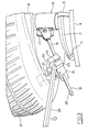
- Figure 1 is a partial side view of a tyre removal machine on which the implement of the invention, shown partly sectioned, is installed.
- Figure 2 is the view from II of Figure 1.
- Figure 3 is a partial perspective view of one of the components of the implement of the invention.
- Figures 4 and 6 show in succession the steps involved in mounting the tyre on the wheel rim using the machine of the invention.
- Figure 5 is the view from V of Figure 4.
- Said figures show the self-centering unit 1 extending upwards from the base 2 of a tyre removal machine 3.
- the self-centering unit 1 comprises a usual plate 4 provided with jaws 5 for gripping the support and locking device 6 for a wheel 7, this latter comprising the wheel rim 8, the tyre 9 and the ring 10 of elastomeric material.
- the support and locking device 6 for the wheel 7 comprises a lower circular member 11 in the shape of an inverted dish, the edge of which is intended to be gripped by the jaws 5 of the self-centering unit 1.
- Said member centrally supports a vertical shaft 12, the upper portion 120 of which is threaded; below the threaded portion, the shaft 12 supports a cup member 13 against which the hub 80 of the wheel rim 8 rests when mounted on the shaft 12.
- the wheel rim 8 is locked onto the support device 6 by a centering cone 14 and a quick-locking nut 15, of known type.
- the shaft 12 presents an annular sunken portion containing a cylindrical bush 16 free to rotate about the axis A of the support device 6.
- Said bush 16 consists of two identical semi-cylindrical parts, each of which is provided with lugs 17, said two parts being joined together by usual screws to form the cylindrical bush 16.
- a rod 18 of rectangular cross-section is hinged to one of the lugs 17, and is free to rotate within the plane of the axis A of said support device 6.
- a block 19 is mounted and freely slidable on said rod 18 and is prevented from escaping from the rod 18 by a stop 20 positioned at the free end of the rod.
- a hook-shaped tool 21 is associated with the block 19, to interact with the edge of the lower bead of the tyre 9 during the mounting of the tyre on the wheel rim 8.
- said tool 21 is fixed to a profiled member 22 hinged to the block 19 and hence free to undergo partial rotations with respect to the block.
- the member 22 is also provided on one side with a portion 23 presenting two seats 24 and 25 for receiving a lever 26 used by the operator while mounting the tyre 9 on the wheel rim, as clarified hereinafter.
- the axis of the seat 24 is orientated downwards from the axis of the rod 18, in the direction of the axis A of the support unit 6, and that the axis of the seat 25 is orientated upwards from the axis of the rod 18, in the direction of the axis A of the support unit 6.
- a vertical column 27 projects upwards from the rear of the base 2 of the tyre removal machine, and is provided with a guide 28 on which there slides a slide 29 supporting a cylinder 30 fixed to the slide 29 by two locking elements 310 of horseshoe shape.
- the slide is driven with vertical translation by a cylinder-piston unit 40, the piston rod 41 of which is fixed to the lower end of the cylinder 30.
- the sleeve 31 Free to rotate about the cylinder 30 but axially locked by two rings 32 fixed to the cylinder 30.
- the sleeve 31 supports an internally hollow cylindrical member 33 of horizontal axis internally containing a rod 34, the free end of which carries an idle roller 35 arranged to interact with the side-wall of the tyre or with the edge of the tyre bead while the tyre is being mounted on the wheel rim.
- the lateral surface of the member 33 comprises a series of holes 36 into which there is inserted a pin 37, one end of which is inserted into a hole, not shown, present in the rod 34 to prevent axial translation of the rod. It should be noted that each of the holes 36 corresponds to a determined diameter of the wheel rim on which the operation is to be carried out.
- an arm 38 which is free to rotate about the cylinder 30 and carries at its free end a second arm 39 which in its turn is free to rotate with respect to the arm 38.
- the axis of rotation of the arm 39 coincides with the axis A of the support device for the wheel 7.
- a sleeve 42 lowerly carrying a member 43 arranged to press against the side-wall of the tyre during the mounting operation.
- the member 43 consists of a vertical rod 44, to the lower end of which there is fixed a pad of elastomeric material.
- the wheel rim 8 is firstly positioned on the support device 6 and then locked in position by the centering cone 14 and the quick locking nut 15. It should be noted that to be able to carry out the mounting operation the smaller diameter edge of the wheel rim must be facing upwards as shown in the figures.
- the operator has then to return the tyre lower bead into the appropriate seat in the wheel rim.
- he uses the tool 21 in combination with the roller 35.
- the smaller-diameter tyre bead is inserted into the matching seat present in the wheel rim by using both the roller 35 and the member 43.
- the roller 35 is positioned at the tyre bead and the arm 38 is rotated such as to bring its free end onto the axis A of the support device.
- the pad 45 of the member 43 is then positioned on the side-wall of the tyre, immediately downstream of the roller 35 in the direction of rotation of the self-centering unit 1, and the cylinder-piston unit 40 is lowered so that the roller 35 and the member 43 exert a certain force on the bead and on the side-wall of the tyre respectively.
- the self-centering unit 1 is then rotated, and during rotation the roller 35 inserts the tyre bead into its seat in the wheel rim, the member 43 rotating rigidly with the wheel rim to maintain the bead inserted into the bead retention seat of the wheel rim.
- the tyre and the ring 10 are demounted from the wheel rim very easily.
- the roller 35 is merely positioned against the side-wall of the tyre at the larger diameter bead, and the self-centering unit 1 then rotated.
- the roller 35 is made to rise by the cylinder-piston unit 40. In this manner the tyre and ring are removed from the wheel rim 8 while the self-centering unit 1 rotates.
Landscapes
- Engineering & Computer Science (AREA)
- Mechanical Engineering (AREA)
- Testing Of Balance (AREA)
- Tyre Moulding (AREA)
Applications Claiming Priority (2)
| Application Number | Priority Date | Filing Date | Title |
|---|---|---|---|
| ITRE010007U | 2001-02-28 | ||
| ITRE20010007 ITRE20010007U1 (it) | 2001-02-28 | 2001-02-28 | Attrezzatura perfezionata per lo smontaggio e il montaggio di pneumatici autoportanti, del tipo system pax e simili. |
Publications (2)
| Publication Number | Publication Date |
|---|---|
| EP1236589A2 true EP1236589A2 (de) | 2002-09-04 |
| EP1236589A3 EP1236589A3 (de) | 2003-07-23 |
Family
ID=11454027
Family Applications (1)
| Application Number | Title | Priority Date | Filing Date |
|---|---|---|---|
| EP02075247A Withdrawn EP1236589A3 (de) | 2001-02-28 | 2002-01-21 | Verbesserte Vorrichtung zum Montieren und Abmontieren von "system pax"- Leerlaufreifen und ähnliche |
Country Status (2)
| Country | Link |
|---|---|
| EP (1) | EP1236589A3 (de) |
| IT (1) | ITRE20010007U1 (de) |
Cited By (4)
| Publication number | Priority date | Publication date | Assignee | Title |
|---|---|---|---|---|
| US6863110B1 (en) * | 2001-11-01 | 2005-03-08 | Service Station Products Company | Method and apparatus for removing vehicle wheel |
| EP1844959A1 (de) * | 2006-04-14 | 2007-10-17 | Bridgestone Corporation | Verfahren und Gerät zum Entfernen eines mit einem starren inneren Notlaufring versehenen Reifens |
| US7438110B2 (en) | 2006-11-03 | 2008-10-21 | Kia Motors Corporation | Tire mounting apparatus |
| US8147895B2 (en) | 2005-02-17 | 2012-04-03 | Conopco, Inc. | Process for the preparation of a spreadable dispersion |
Family Cites Families (1)
| Publication number | Priority date | Publication date | Assignee | Title |
|---|---|---|---|---|
| IT1309757B1 (it) * | 1999-04-30 | 2002-01-30 | Corghi Spa | Macchina smontagomme per pneumatici del tipo "system pax" e simili. |
-
2001
- 2001-02-28 IT ITRE20010007 patent/ITRE20010007U1/it unknown
-
2002
- 2002-01-21 EP EP02075247A patent/EP1236589A3/de not_active Withdrawn
Non-Patent Citations (1)
| Title |
|---|
| None |
Cited By (5)
| Publication number | Priority date | Publication date | Assignee | Title |
|---|---|---|---|---|
| US6863110B1 (en) * | 2001-11-01 | 2005-03-08 | Service Station Products Company | Method and apparatus for removing vehicle wheel |
| US8147895B2 (en) | 2005-02-17 | 2012-04-03 | Conopco, Inc. | Process for the preparation of a spreadable dispersion |
| EP1844959A1 (de) * | 2006-04-14 | 2007-10-17 | Bridgestone Corporation | Verfahren und Gerät zum Entfernen eines mit einem starren inneren Notlaufring versehenen Reifens |
| US7946016B2 (en) | 2006-04-14 | 2011-05-24 | Bridgestone Corporation | Method and machine for removing a tyre fitted with a rigid inner run-flat ring |
| US7438110B2 (en) | 2006-11-03 | 2008-10-21 | Kia Motors Corporation | Tire mounting apparatus |
Also Published As
| Publication number | Publication date |
|---|---|
| ITRE20010007V0 (it) | 2001-02-28 |
| EP1236589A3 (de) | 2003-07-23 |
| ITRE20010007U1 (it) | 2002-08-28 |
Similar Documents
| Publication | Publication Date | Title |
|---|---|---|
| EP0947360B1 (de) | Reifendemontiervorrichtung und Zubehör | |
| EP1157860B2 (de) | Reifenabdrückvorrichtung für ein Raddemontiergerät, und Raddemontiergerät mit einer solchen Vorrichtung | |
| US6619362B2 (en) | Automatic tyre removal and mounting device and tyre removal machines equipped therewith | |
| US9168797B2 (en) | Tyre demounting machine | |
| US7343955B2 (en) | Tire changing machine | |
| EP1052120B1 (de) | Mehrzweckstation für das Montieren und Demontieren von Konvetionell- und Spezialreifen | |
| US7438109B2 (en) | Tire changer | |
| CN101754876B (zh) | 用于换胎机的卡盘 | |
| US20010042602A1 (en) | Wheel rim locking device for tyre removal machines | |
| EP1048496B1 (de) | Reifendemontiervorrichtung für "system pax"- Reifen oder ähnlichem | |
| US3942575A (en) | Portable tire changing apparatus and method for mounting and demounting heavy duty tires on a wheel | |
| EP1844959B1 (de) | Verfahren und Gerät zum Entfernen eines mit einem starren inneren Notlaufring versehenen Reifens | |
| EP1844960B1 (de) | Verfahren und Gerät zum Entfernen und Montieren eines mit einem starren inneren Notlaufring versehenen Reifens | |
| US6145566A (en) | Center post tire changing apparatus | |
| JP2000225819A (ja) | 特殊タイヤ取付け・取外し用機械 | |
| EP1167087B1 (de) | Vorrichtung zur Operation auf "system pax"- Reifen oder ähnlichem | |
| EP0987130A2 (de) | Reifendemontiergerät | |
| US20080251176A1 (en) | Method and unit for mounting on a rim a tire provided with a safety support | |
| US3181587A (en) | Tire removal and assembly device | |
| US9573427B2 (en) | Tire machine mount and demount head and clamp foot adapter | |
| EP2905153B1 (de) | Reifenwechselmaschine | |
| EP1717064A1 (de) | Werkzeug für die Montage / Demontage von Fahrzeugreifen | |
| EP1236589A3 (de) | Verbesserte Vorrichtung zum Montieren und Abmontieren von "system pax"- Leerlaufreifen und ähnliche | |
| EP1717065A1 (de) | Werkzeug für die Montage/ Demontage von Fahrzeugreifen |
Legal Events
| Date | Code | Title | Description |
|---|---|---|---|
| PUAI | Public reference made under article 153(3) epc to a published international application that has entered the european phase |
Free format text: ORIGINAL CODE: 0009012 |
|
| AK | Designated contracting states |
Kind code of ref document: A2 Designated state(s): AT BE CH CY DE DK ES FI FR GB GR IE IT LI LU MC NL PT SE TR |
|
| AX | Request for extension of the european patent |
Free format text: AL;LT;LV;MK;RO;SI |
|
| PUAL | Search report despatched |
Free format text: ORIGINAL CODE: 0009013 |
|
| AK | Designated contracting states |
Designated state(s): AT BE CH CY DE DK ES FI FR GB GR IE IT LI LU MC NL PT SE TR |
|
| AX | Request for extension of the european patent |
Extension state: AL LT LV MK RO SI |
|
| AKX | Designation fees paid | ||
| REG | Reference to a national code |
Ref country code: DE Ref legal event code: 8566 |
|
| STAA | Information on the status of an ep patent application or granted ep patent |
Free format text: STATUS: THE APPLICATION IS DEEMED TO BE WITHDRAWN |
|
| 18D | Application deemed to be withdrawn |
Effective date: 20040124 |