EP1236611A1 - Kipperaufbau mit verbesserter Bordwandlagerung - Google Patents
Kipperaufbau mit verbesserter Bordwandlagerung Download PDFInfo
- Publication number
- EP1236611A1 EP1236611A1 EP02290424A EP02290424A EP1236611A1 EP 1236611 A1 EP1236611 A1 EP 1236611A1 EP 02290424 A EP02290424 A EP 02290424A EP 02290424 A EP02290424 A EP 02290424A EP 1236611 A1 EP1236611 A1 EP 1236611A1
- Authority
- EP
- European Patent Office
- Prior art keywords
- bucket
- edge
- cylindrical portion
- axis
- articulation
- Prior art date
- Legal status (The legal status is an assumption and is not a legal conclusion. Google has not performed a legal analysis and makes no representation as to the accuracy of the status listed.)
- Withdrawn
Links
- 230000002787 reinforcement Effects 0.000 claims description 5
- 230000003014 reinforcing effect Effects 0.000 claims description 2
- 238000006073 displacement reaction Methods 0.000 abstract description 2
- 235000003434 Sesamum indicum Nutrition 0.000 description 6
- 244000000231 Sesamum indicum Species 0.000 description 6
- 239000000463 material Substances 0.000 description 6
- 239000002184 metal Substances 0.000 description 3
- 230000000007 visual effect Effects 0.000 description 3
- 230000000295 complement effect Effects 0.000 description 2
- 239000012535 impurity Substances 0.000 description 2
- 238000012550 audit Methods 0.000 description 1
- 238000009432 framing Methods 0.000 description 1
- 230000000873 masking effect Effects 0.000 description 1
- 238000005192 partition Methods 0.000 description 1
- 238000007790 scraping Methods 0.000 description 1
Images
Classifications
-
- B—PERFORMING OPERATIONS; TRANSPORTING
- B60—VEHICLES IN GENERAL
- B60P—VEHICLES ADAPTED FOR LOAD TRANSPORTATION OR TO TRANSPORT, TO CARRY, OR TO COMPRISE SPECIAL LOADS OR OBJECTS
- B60P1/00—Vehicles predominantly for transporting loads and modified to facilitate loading, consolidating the load, or unloading
- B60P1/04—Vehicles predominantly for transporting loads and modified to facilitate loading, consolidating the load, or unloading with a tipping movement of load-transporting element
- B60P1/26—Means for controlling movement of tailboards or sideboards
-
- B—PERFORMING OPERATIONS; TRANSPORTING
- B62—LAND VEHICLES FOR TRAVELLING OTHERWISE THAN ON RAILS
- B62D—MOTOR VEHICLES; TRAILERS
- B62D33/00—Superstructures for load-carrying vehicles
- B62D33/02—Platforms; Open load compartments
- B62D33/023—Sideboard or tailgate structures
- B62D33/027—Sideboard or tailgate structures movable
- B62D33/03—Sideboard or tailgate structures movable by swinging down
Definitions
- the invention relates to skips.
- Drop sides are generally bordered by partitions which, when articulated, are called drop sides.
- the drop sides can be articulated from above, or from below. They facilitate loading or unloading the bucket, which can be fixed or tilting. We usually finds top hinged drop sides at the rear of the skips tilting vehicle to facilitate unloading.
- the drop sides articulated from below generally form the side walls of the bucket, and aim to facilitate both the loading and unloading of the bucket by the side.
- the invention relates to a bucket comprising a bottom and at least one drop side extending along an edge of said bottom and articulated relative to said bottom about an axis parallel to said edge.
- a bucket of this type is known from document EP-A-0 623 502, in the name of the plaintiff.
- edge and the side wall have surfaces complementary cylindrical.
- the drop side tends, when it opens and from closing, scraping against the edge of the bottom of the bucket, which tends to damage them both, especially when the edge has a sharp edge. Seizure can also occur which interferes with the movement of the drop side, especially when the edge of the bottom of the bucket and the drop side have complementary cylindrical surfaces, impurities tending to creep between the edge of the bottom of the bucket and the drop side, impurities of which there is difficult to get rid of without removing the drop side.
- the edge of the bottom of the bucket is visible from the outside of the bucket, both in the closed position and in the open from the drop side.
- the bucket does not offer a visual appearance perfectly clean.
- the invention provides a bucket having a bottom and at less a drop side extending along an edge of said bottom, and articulated relative to said bottom around an axis parallel to said edge, where the axis of articulation of said side panel is moved away from said edge towards the outside, and where said side panel has the end a cylindrical portion adapted to cooperate, on at least part of its angular movement, with said edge.
- the cylindrical portion of the drop side forms an obstacle to projections of materials during a possible transport of the bucket.
- the cylindrical portion has a cross section which belongs to a circle centered on the axis of articulation, and tangent to said edge.
- the edge of the bucket is for example formed by a rim having a surface at the right of which is the axis of articulation, and with which is adapted to cooperate with said cylindrical portion.
- the articulation of the drop side can be achieved by means of less a hinge comprising a tab integral with said bottom and projecting from this, as well as a yoke provided on said drop side and formed by a notch formed in said cylindrical portion, bordered by two plates opposite and integral with said cylindrical portion, said tab being inserted in said notch between the plates, said tab and said plates being joined by a rod forming the hinge axis of the drop side.
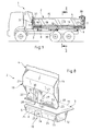
- Figure 1 a vehicle 1 carrying a bucket 2 comprising a bottom 3 laterally bordered by two side panels 4 of which only one is visible in Figure 1.
- the bottom 3 has a rectilinear, or substantially lateral edge 5 straight, along which the drop side 4 extends over the entire length of the bucket 2, between a front post 6 and a rear post 7.
- the drop side 4 is articulated from below relative to the bottom 3, around an axis Parallel, or substantially parallel, to edge 5 by means of hinges, in the occurrence of the front 8 and rear 9 hinges, and a central hinge 10.
- the bottom of the bucket 3 has a substantially flat floor 11, thus a cross member 12 extended over the entire length of the bucket 2, forming a rim of the skip bottom 3, disposed under the floor 11 and subject to the latter.
- the rim 12 is in the form of a metal section section transverse in the shape of a trapezoid, the small base of which faces downwards, and which forms a reinforcement of the bottom of the bucket 3.
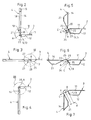
- the rim 12 has a surface 13, said to be external, flat or substantially flat, which is inclined relative to normal to the floor 11, such that it appears in Figures 2 to 7.
- the side wall 4 is able to pivot relative to the bottom of the bucket 3 between a so-called closed position in which it forms a right or substantially right angle with the bottom of the bucket 3 and hinders access to the interior of the bucket 2 ( Figures 2 and 5), and a so-called open position in which it hangs freely from the bottom of bucket 3 and thus allows access to the interior of the bucket 2 ( Figures 4 and 7).
- a intermediate position, in which the drop side 4 is located in the extension of the bottom of the bucket 3, is illustrated in FIGS. 3 and 6.
- the drop side 4 is now described, assumed to be fixed in the closed position for more convenience.
- the side wall 4 has a substantially flat wall 14 formed by a metal plate, bordered upwards by a crosspiece 15, called upper, towards front by a front upright 16, rear by a rear upright 17.
- the drop side 4 can be reinforced by a series of parallel longitudinal members 18 arranged oblique.
- the side wall 4 is bordered downwards by a crosspiece 19, called the bottom, formed by a metal profile secured to the wall 14 along a lower edge 20 of it.
- This lower cross member 19 has an upper portion 21, located in line with the wall 14 and having a U-shaped cross section or trapezoid-shaped, extended by a lower portion 22 projecting from the wall 14 and curved outwards.
- the hinge axis A of the side panel 4 is moved away from edge 5 of the platform base 3 outwardly, being situated in line with the outer surface 13 of flange 12. It is noted d the distance of the hinge axis A at the outer surface 13 of the rim 12, measured along the normal n to this surface 13, passing through the hinge axis A.
- the lower portion 22 of the lower cross member 19 is cylindrical. She is adapted to cooperate on at least part of the angular displacement of the drop side 4, with the outer surface 13 of the rim 12.
- the cylindrical lower portion 22 belongs to a circle C centered on the articulation axis A, and which has a radius r equal to the distance d , so that this circle C is tangent to the outer surface 13 of the ledge 12.
- cylindrical portion 22 extends angularly, around the axis of articulation A, according to an angular opening ⁇ preferably understood between 90 ° and 180 °. According to an embodiment illustrated in FIGS. 5 to 7, this angular opening ⁇ is substantially equal to 120 °.
- the cylindrical portion 22 follows the circle C during the pivoting of the drop side 4, so that, whatever the angular position of the drop side 4 between the closed position and a discarded position, called limit contact position, in which the drop side 4 forms with the bottom of the bucket 3 an angle equal to the opening angular ⁇ , its cylindrical portion 22 is located, via a face 23 in contact with the outer surface 13 of the rim 12 along a fixed line 24 of contact parallel to the hinge axis A.
- the cylindrical portion 22 leaves the outer surface 13, so that a gap appears between the side wall 4 and the skip bottom 3, this gap allowing the flow of materials initially trapped between the lower cross member 21 and the flange 12.
- hinge central 10 allowing the articulation of the drop side 4 to the bottom of the bucket 3, in reference to Figures 2 to 4, and to Figure 8.
- the hinge 10 comprises on the one hand a tab 25 integral with the bottom of bucket 3 and projecting therefrom outwards, in line with the external surface 13 edge 12.
- this tab 25 is made a through hole 26 in section circular, centered on the hinge axis A of the drop side 4.
- the hinge 10 further comprises a yoke 27 provided on the side wall 4, and formed by a notch 28 formed in the cylindrical portion 22 to height of the articulation axis A, and by two facing plates 29, 30 integral of the cylindrical portion 22 and framing the notch 28.
- the plates 29, 30 are for example welded to the lower cross member 19, and in each of them a through hole 31, 32 with a circular section centered on the axis is made hinge A of the drop side 4.
- the tab 25 is inserted into the notch 28 between the plates 29, 30, the leg 25 and the plates 29, 30 being joined by a cylindrical rod 33 passing through the holes 26, 31, 32 and forming the hinge pin A of the drop side 4.
- the opening and closing of the side panel 4 can be controlled from mechanically by means of a hydraulic opening device 36 fixed by example under the skip bottom 3. Furthermore, the drop side 4 can be maintained in the closed position by a hydraulic locking device 36 'fixed by example to one of the posts 6, 7 of the bucket 2. For the realization of such devices, reference may be made in particular to document EP-A-0 623 502.
- Locking the drop side 4 in the closed position can be completed at means of shims 37, 38 associated with the front and rear uprights 16.17.
- tubular part 34 shown in broken lines on FIG. 6 extended parallel to the hinge axis A of the drop side 4, and secured to a free end 35 of the cylindrical portion 22, which could be sharp.
- the cylindrical portion can extend at an angular opening greater than 120 °.
- this cylindrical portion is bent towards and up to the upper portion of the profile forming the bottom rail.
Landscapes
- Engineering & Computer Science (AREA)
- Transportation (AREA)
- Mechanical Engineering (AREA)
- Chemical & Material Sciences (AREA)
- Combustion & Propulsion (AREA)
- Load-Engaging Elements For Cranes (AREA)
Applications Claiming Priority (2)
| Application Number | Priority Date | Filing Date | Title |
|---|---|---|---|
| FR0102733 | 2001-02-28 | ||
| FR0102733A FR2821324B1 (fr) | 2001-02-28 | 2001-02-28 | Benne comportant une articulation perfectionnee d'une ridelle par rapport au fond de benne |
Publications (1)
| Publication Number | Publication Date |
|---|---|
| EP1236611A1 true EP1236611A1 (de) | 2002-09-04 |
Family
ID=8860553
Family Applications (1)
| Application Number | Title | Priority Date | Filing Date |
|---|---|---|---|
| EP02290424A Withdrawn EP1236611A1 (de) | 2001-02-28 | 2002-02-21 | Kipperaufbau mit verbesserter Bordwandlagerung |
Country Status (2)
| Country | Link |
|---|---|
| EP (1) | EP1236611A1 (de) |
| FR (1) | FR2821324B1 (de) |
Citations (5)
| Publication number | Priority date | Publication date | Assignee | Title |
|---|---|---|---|---|
| DE834179C (de) * | 1951-02-02 | 1952-03-17 | Josef Wimmer | Schlitzabdeckung zwischen Seitenwand und Kastenboden an Fahrzeugen |
| GB1341508A (de) * | 1971-10-07 | 1973-12-25 | ||
| JPS58139880A (ja) * | 1982-02-15 | 1983-08-19 | Tokyu Car Corp | 煽戸ヒンジ装置 |
| DE3339224A1 (de) * | 1982-11-02 | 1984-05-03 | Hans Brantner & Sohn Fahrzeugbaugesellschaft mbH, 2136 Laa an der Thaya | Ladeplattform |
| EP0623502A1 (de) | 1993-05-03 | 1994-11-09 | Marrel | Steuersystem für eine an ihrer Unterseite beweglich befestigte Fahrzeuglade-Bordwand |
-
2001
- 2001-02-28 FR FR0102733A patent/FR2821324B1/fr not_active Expired - Fee Related
-
2002
- 2002-02-21 EP EP02290424A patent/EP1236611A1/de not_active Withdrawn
Patent Citations (5)
| Publication number | Priority date | Publication date | Assignee | Title |
|---|---|---|---|---|
| DE834179C (de) * | 1951-02-02 | 1952-03-17 | Josef Wimmer | Schlitzabdeckung zwischen Seitenwand und Kastenboden an Fahrzeugen |
| GB1341508A (de) * | 1971-10-07 | 1973-12-25 | ||
| JPS58139880A (ja) * | 1982-02-15 | 1983-08-19 | Tokyu Car Corp | 煽戸ヒンジ装置 |
| DE3339224A1 (de) * | 1982-11-02 | 1984-05-03 | Hans Brantner & Sohn Fahrzeugbaugesellschaft mbH, 2136 Laa an der Thaya | Ladeplattform |
| EP0623502A1 (de) | 1993-05-03 | 1994-11-09 | Marrel | Steuersystem für eine an ihrer Unterseite beweglich befestigte Fahrzeuglade-Bordwand |
Non-Patent Citations (1)
| Title |
|---|
| PATENT ABSTRACTS OF JAPAN vol. 007, no. 257 (M - 256) 16 November 1983 (1983-11-16) * |
Also Published As
| Publication number | Publication date |
|---|---|
| FR2821324B1 (fr) | 2003-08-08 |
| FR2821324A1 (fr) | 2002-08-30 |
Similar Documents
| Publication | Publication Date | Title |
|---|---|---|
| EP1081063B1 (de) | Vorrichtung zum automatisch durch Schwerkraft Verriegeln und Entriegeln des Deckels eines Behälters sowie Behälter mit einer derartigen Vorrichtung | |
| LU88046A1 (de) | ||
| FR2666076A1 (fr) | Conteneur comprenant un verrou de couvercle. | |
| EP0408478A1 (de) | Abgabeverschluss mit abreissbarem Garantiestreifen | |
| WO2020193645A1 (fr) | Rack de stockage a acces facilite | |
| FR2928633A1 (fr) | Benne pour le transport et/ou le stockage de charge(s) | |
| EP3763568B1 (de) | Fördergefäss, das mit einer klappe ausgestattet ist | |
| EP1236611A1 (de) | Kipperaufbau mit verbesserter Bordwandlagerung | |
| EP0857448B1 (de) | Grillrost aus scharnierartig verbundenen Rostelementen | |
| FR2837806A1 (fr) | Toit a ouverture du type accordeon pour conteneur du type benne et conteneur ainsi equipe | |
| FR2978960A1 (fr) | Conteneur de collecte des dechets dote d'un systeme d'actionnement de trappes perfectionne | |
| EP0591028B1 (de) | Unteres Bordwandscharnier für Fahrzeugladepritschen | |
| EP1134341B1 (de) | Gelenktürsystem für Fahrzeuge, Behälter und dergleichen | |
| FR2847781A1 (fr) | Meuble de rangement, du type comportant un rideau deformable de fermeture monte coulissant | |
| FR3029187A1 (fr) | Dispositif de chargement en dechets d'une benne de dechetterie depuis une plateforme | |
| FR3041946A1 (fr) | Dispositif de chargement en dechets d'un receptacle, tel qu'une benne de dechetterie depuis une plate-forme | |
| FR2730254A1 (fr) | Support mobile de panneau de signalisation | |
| EP0728608A1 (de) | Gelenktürsystem für Fahrzeuge, Behälter und ähnliche Verwendungen | |
| FR2942263A1 (fr) | Dispositif d'ouverture/fermeture a double charniere | |
| FR2758802A1 (fr) | Conteneur forme de deux coquilles pivotantes, notamment pour la recuperation de materiaux | |
| FR2866867A1 (fr) | Bennes a dispositif antivol inamovible | |
| EP0225268B1 (de) | Ladevorrichtung für Müllsammelbehälter auf Müllfahrzeugen | |
| FR3112134A1 (fr) | Quai de déchargement équipé d’au moins un dispositif de déchargement comportant une paroi supérieure inclinée | |
| EP0211733A1 (de) | Vorrichtung zum Halten einer Containertür in geschlossener Stellung und Container mit einer solchen Vorrichtung | |
| WO2011070263A1 (fr) | Ensemble a cadre et tampon de fermeture du cadre notamment pour regard de chaussee |
Legal Events
| Date | Code | Title | Description |
|---|---|---|---|
| PUAI | Public reference made under article 153(3) epc to a published international application that has entered the european phase |
Free format text: ORIGINAL CODE: 0009012 |
|
| AK | Designated contracting states |
Kind code of ref document: A1 Designated state(s): AT BE CH CY DE DK ES FI FR GB GR IE IT LI LU MC NL PT SE TR |
|
| AX | Request for extension of the european patent |
Free format text: AL;LT;LV;MK;RO;SI |
|
| 17P | Request for examination filed |
Effective date: 20020808 |
|
| AKX | Designation fees paid |
Designated state(s): DE ES FR |
|
| STAA | Information on the status of an ep patent application or granted ep patent |
Free format text: STATUS: THE APPLICATION IS DEEMED TO BE WITHDRAWN |
|
| 18D | Application deemed to be withdrawn |
Effective date: 20060901 |