EP1236634A1 - Verfahren und Vorrichtung zur Feststellung des Zustandes eines Gleises - Google Patents
Verfahren und Vorrichtung zur Feststellung des Zustandes eines Gleises Download PDFInfo
- Publication number
- EP1236634A1 EP1236634A1 EP02251176A EP02251176A EP1236634A1 EP 1236634 A1 EP1236634 A1 EP 1236634A1 EP 02251176 A EP02251176 A EP 02251176A EP 02251176 A EP02251176 A EP 02251176A EP 1236634 A1 EP1236634 A1 EP 1236634A1
- Authority
- EP
- European Patent Office
- Prior art keywords
- track
- rail
- crack
- information
- cracks
- Prior art date
- Legal status (The legal status is an assumption and is not a legal conclusion. Google has not performed a legal analysis and makes no representation as to the accuracy of the status listed.)
- Withdrawn
Links
- 238000000034 method Methods 0.000 title claims abstract description 118
- 238000007689 inspection Methods 0.000 claims abstract description 28
- 230000005855 radiation Effects 0.000 claims description 31
- 238000007635 classification algorithm Methods 0.000 claims description 13
- 238000013528 artificial neural network Methods 0.000 claims description 12
- 238000004140 cleaning Methods 0.000 claims description 12
- 238000013016 damping Methods 0.000 claims description 6
- 230000007246 mechanism Effects 0.000 claims description 4
- 238000001514 detection method Methods 0.000 abstract description 14
- 230000003137 locomotive effect Effects 0.000 abstract description 8
- 238000004458 analytical method Methods 0.000 description 40
- 238000003384 imaging method Methods 0.000 description 24
- 238000004422 calculation algorithm Methods 0.000 description 15
- 230000007547 defect Effects 0.000 description 13
- 238000005286 illumination Methods 0.000 description 12
- 230000035515 penetration Effects 0.000 description 7
- 238000003708 edge detection Methods 0.000 description 5
- 230000000149 penetrating effect Effects 0.000 description 5
- 238000004590 computer program Methods 0.000 description 4
- 230000006870 function Effects 0.000 description 4
- 230000003287 optical effect Effects 0.000 description 4
- 238000012545 processing Methods 0.000 description 4
- 238000003860 storage Methods 0.000 description 4
- 238000012360 testing method Methods 0.000 description 4
- 238000013459 approach Methods 0.000 description 3
- 230000004907 flux Effects 0.000 description 3
- 238000010845 search algorithm Methods 0.000 description 3
- 230000003321 amplification Effects 0.000 description 2
- 239000013590 bulk material Substances 0.000 description 2
- 238000004891 communication Methods 0.000 description 2
- 238000013481 data capture Methods 0.000 description 2
- 239000000428 dust Substances 0.000 description 2
- 238000011065 in-situ storage Methods 0.000 description 2
- 238000005304 joining Methods 0.000 description 2
- 238000004519 manufacturing process Methods 0.000 description 2
- 238000007620 mathematical function Methods 0.000 description 2
- 239000002184 metal Substances 0.000 description 2
- 238000003199 nucleic acid amplification method Methods 0.000 description 2
- 230000035945 sensitivity Effects 0.000 description 2
- 238000012546 transfer Methods 0.000 description 2
- XLYOFNOQVPJJNP-UHFFFAOYSA-N water Substances O XLYOFNOQVPJJNP-UHFFFAOYSA-N 0.000 description 2
- 241000931526 Acer campestre Species 0.000 description 1
- 206010012411 Derailment Diseases 0.000 description 1
- 238000012896 Statistical algorithm Methods 0.000 description 1
- 230000009471 action Effects 0.000 description 1
- 230000002547 anomalous effect Effects 0.000 description 1
- 230000009286 beneficial effect Effects 0.000 description 1
- 230000008901 benefit Effects 0.000 description 1
- 238000004364 calculation method Methods 0.000 description 1
- 230000008859 change Effects 0.000 description 1
- 230000000295 complement effect Effects 0.000 description 1
- 238000005336 cracking Methods 0.000 description 1
- 230000001419 dependent effect Effects 0.000 description 1
- 238000011161 development Methods 0.000 description 1
- 230000004069 differentiation Effects 0.000 description 1
- 231100001261 hazardous Toxicity 0.000 description 1
- 230000003993 interaction Effects 0.000 description 1
- 230000001788 irregular Effects 0.000 description 1
- 239000000463 material Substances 0.000 description 1
- 238000005259 measurement Methods 0.000 description 1
- 230000005055 memory storage Effects 0.000 description 1
- 238000012986 modification Methods 0.000 description 1
- 230000004048 modification Effects 0.000 description 1
- 238000012544 monitoring process Methods 0.000 description 1
- 238000007781 pre-processing Methods 0.000 description 1
- 230000008569 process Effects 0.000 description 1
- 230000000717 retained effect Effects 0.000 description 1
- 238000005070 sampling Methods 0.000 description 1
- 238000011896 sensitive detection Methods 0.000 description 1
- 239000002689 soil Substances 0.000 description 1
- 239000007787 solid Substances 0.000 description 1
- 238000012066 statistical methodology Methods 0.000 description 1
- 238000002604 ultrasonography Methods 0.000 description 1
- 230000000007 visual effect Effects 0.000 description 1
- 238000011179 visual inspection Methods 0.000 description 1
Images





Classifications
-
- B—PERFORMING OPERATIONS; TRANSPORTING
- B61—RAILWAYS
- B61L—GUIDING RAILWAY TRAFFIC; ENSURING THE SAFETY OF RAILWAY TRAFFIC
- B61L23/00—Control, warning or like safety means along the route or between vehicles or trains
- B61L23/04—Control, warning or like safety means along the route or between vehicles or trains for monitoring the mechanical state of the route
- B61L23/042—Track changes detection
- B61L23/044—Broken rails
-
- B—PERFORMING OPERATIONS; TRANSPORTING
- B61—RAILWAYS
- B61K—AUXILIARY EQUIPMENT SPECIALLY ADAPTED FOR RAILWAYS, NOT OTHERWISE PROVIDED FOR
- B61K9/00—Railway vehicle profile gauges; Detecting or indicating overheating of components; Apparatus on locomotives or cars to indicate bad track sections; General design of track recording vehicles
- B61K9/08—Measuring installations for surveying permanent way
- B61K9/10—Measuring installations for surveying permanent way for detecting cracks in rails or welds thereof
-
- B—PERFORMING OPERATIONS; TRANSPORTING
- B61—RAILWAYS
- B61L—GUIDING RAILWAY TRAFFIC; ENSURING THE SAFETY OF RAILWAY TRAFFIC
- B61L23/00—Control, warning or like safety means along the route or between vehicles or trains
- B61L23/04—Control, warning or like safety means along the route or between vehicles or trains for monitoring the mechanical state of the route
- B61L23/042—Track changes detection
- B61L23/047—Track or rail movements
-
- B—PERFORMING OPERATIONS; TRANSPORTING
- B61—RAILWAYS
- B61L—GUIDING RAILWAY TRAFFIC; ENSURING THE SAFETY OF RAILWAY TRAFFIC
- B61L2205/00—Communication or navigation systems for railway traffic
- B61L2205/04—Satellite based navigation systems, e.g. global positioning system [GPS]
Definitions
- This invention relates to determining track condition.
- the invention relates to crack detection and alignment checking in tracks. Aspects of the invention relate to inspecting the condition of a track, to identifying the location and an aspect of a noteworthy situation and to determining whether a crack is present in a section of track. Examples of the invention described below relate to tracks in a transport system, in particular railway tracks.
- rack used herein should be interpreted broadly (unless it is clear from the context otherwise) to refer to any kind of flaw, defect or damage to the track. Such “cracks” may be the result of manufacture and/or damage during service.
- One known method for identifying cracks in rails involves the use of ultrasound. This requires the testing equipment to be in direct contact with the rail, which restricts the speed of a testing vehicle which in turn means longer inspection times and further disruption to scheduled operation.
- An object of embodiments of the invention is to solve and/or mitigate one or more of the aforementioned problems.
- a method of inspecting the condition of a track used in a transport system comprising: fitting an inspection device to a transport vehicle of the transport system; and using the device to inspect the track.
- the track is a railway track
- the vehicle is a train
- the transport system is a railway.
- the invention also covers other types of transport systems and vehicles including, but not restricted to, monorails, trams, cable cars and roller coasters.
- the track may include any appropriate guide for the vehicle.
- the device may comprise a single unit, or more than one unit.
- the device is used during a scheduled service of the vehicle.
- the time taken for inspection and thus the cost is reduced, and disruption to normal services can be minimised.
- Embodiments of the invention described herein are able to be used on a vehicle running at variable speeds ranging from very low speeds to above about 140 mph in some examples.
- the device is used spaced apart from the track.
- the vehicle can run at a higher speed during the inspection.
- using the device comprises obtaining information relating to an aspect of the condition of the track.
- aspects of the condition which can be investigated include, the presence of cracks and other defects in the track, and the alignment of the track.
- the information may comprise information relating to the integrity of the track.
- obtaining information comprises emitting radiation towards a portion of the track, and detecting radiation which has interacted with the track.
- the radiation may be any type of radiation which would allow information regarding aspects of the track to be obtained, and may be either pulsed or continuous.
- the radiation is light.
- Interaction may include, for example, reflection, or passing through a portion of the track.
- Obtaining information may comprise using a light source to illuminate a portion of the track and detecting the light emitted by the light source which is reflected by the track.
- information relating to partial cracks in the track may be obtained.
- Obtaining information may comprise using a light source to illuminate a portion of the track and detecting light emitted by the light source which passes through the track.
- information relating to full cracks in the track may be obtained.
- the radiation is emitted by a laser.
- laser light By using laser light, very small amounts of light from the track can be detected. It is also possible to filter out other light by excluding wavelengths other than the known wavelength of the laser light. It is envisaged, however, that other radiation sources could also be used, for example maser.
- the laser may be a continuous wave laser, or it may be a pulsed laser as this may be beneficial in terms of gating the optical CCD photon collection system.
- a further aspect of the invention provides a method of determining the condition of a track in a transport system, comprising: emitting laser light towards a portion of the track; and detecting laser light emitted which has interacted with the track.
- both light reflected from the track and light passing through the track can be detected using a single source.
- a source and detector pair is used to detect each of type of defect.
- one or more of the different methods for obtaining information may be used, as appropriate.
- detecting the emitted radiation comprises detecting the radiation at an angle to its emission. This reduces the risk of radiation from the source directly hitting the detector, which might damage the sensitive detection equipment.
- Obtaining information may further comprise obtaining an image of the track.
- a camera may be used.
- the image may be used to detect the general condition of the track and/or alignment of the track.
- Preferably the image is the image ahead of the vehicle; this is thought to give a better image.
- Image quality behind the vehicle may be reduced as a result of dust or other objects thrown up by the passing vehicle.
- the headlights at the front of the train may also provide illumination for the camera.
- obtaining information comprises obtaining a plurality of discrete pieces of information.
- the information obtained comprises a sequence of pieces of information.
- the method further comprises varying the rate at which the information is obtained.
- the method includes determining the speed of the vehicle and varying the rate at which the information is obtained relatively to the determined speed of the vehicle.
- the method further comprises obtaining GPS data relating to the location of the vehicle.
- GPS data relating to the location of the vehicle.
- Information relating to the time may also be obtained. This feature is of particular importance and is thus provided independently.
- a further aspect of the invention provides a method of identifying the location and an aspect of a noteworthy situation, comprising: obtaining GPS data relating to the location of an occurrence of the situation from a GPS receiver located at the location of the occurrence; and obtaining information relating to an aspect of the situation from a sensor located at the location of the occurrence.
- GPS can also be used to track the vehicle.
- the method further comprises storing the information together with the GPS data.
- the information and data can then be analysed off-line, for example after the end of the journey.
- the method further comprises transmitting the information together with the GPS data.
- the information can be monitored in real time and an alert can be given if a noteworthy situation is detected.
- Obtaining information from a sensor may comprise obtaining an image from a camera.
- the information may, for example, comprise an image of the occurrence.
- a noteworthy situation may, for example, be a crack or flaw in a track.
- the method further comprises analysing the information to determine the condition of a track. This feature is of particular importance and is thus provided independently.
- a further aspect of the invention provides a method of determining the condition of the track in a transport system, comprising: receiving information pertaining to the condition of the track; and analysing the information in order to determine the condition of the track.
- the information may comprise a sequence of images of the track.
- the image may comprise a physical image and/or data relating to an image, for example an electronic or digital representation of an image.
- Preferably analysing the information comprises classifying information depending on whether it contains a feature related to a crack.
- the classification may comprise classifying each image.
- analysing the information comprises classifying information including a crack-related feature depending on the type of crack the feature relates to.
- analysing the information comprises comparing an image of a portion of the track with a reference image.
- This can be carried out manually or using a computer. In this way, images of known crack types can be used to obtain a more accurate classification.
- Preferably analysing the information is carried out using a classification algorithm, preferably a neural network based image classification algorithm. It has been found that neural networks are well suited to the image classification task. The system can learn types of crack morphology and can recognise crack-related features. This feature is of particular importance and is thus provided independently.
- a further aspect of the invention provides a method of determining whether a crack is present in a section of track, comprising: obtaining an image of the section of track; and using an image classification algorithm based on a neural network to determine if a crack is present in the section of track.
- the method further comprises determining the dimensions of a feature relating to a crack.
- the method further comprises using the dimensions determined in order to determine the type of crack.
- a reference database can be used to match crack dimensions against known types of crack and thus information relating to the type of crack can be obtained.
- the method further comprises inspecting the information manually in order to determine the condition of the track.
- An expert can look for further information on further track condition aspects not covered by the automatic inspection and/or analyse further any images identified by the automatic system as being of interest.
- the analysis may comprise first identifying a region of the image containing a crack-related feature and then carrying out the detailed analysis only on the identified region. This can greatly reduce the time required for analysis.
- the method further comprises: carrying out a plurality of inspections of a section of track; and comparing the information obtained from the plurality of inspections in order to identify changes in the condition of the track. This makes it possible to monitor the track and any defects over time and to look for worsening condition.
- the method further comprises: identifying a plurality of features corresponding to a plurality of sections of the track in an image; and determining the alignment of the plurality of features. In that way, the alignment of the track can be determined and thus checked against predefined tolerance limits.
- identifying the plurality of features comprises using an edge detection algorithm.
- the information may comprise a sequence of light intensity values, and preferably the method comprises analysing the sequence of light intensity values.
- the presence of cracks can be identified, for example by detecting light or dark sections in the image which may relate to a crack feature.
- Any suitable detector may be used in the various source/detector arrangements.
- a PMT is used.
- a PMT can detect very low levels of light.
- the analysing step may be carried out whilst the inspection device is being used.
- real-time information can be obtained and an alarm may be given if a noteworthy or dangerous situation (for example a crack or defect) is detected.
- the method may comprise analysing the information after the inspection device has been used.
- the information may be analysed off-line. Less on-board processing is required. For example, at the end of the vehicle's journey, a storage device including all the stored information and data may be removed and sent for analysis. This also allows for more extensive analysis of the information.
- the method further comprises cleaning the track ahead of the transport vehicle.
- Any appropriate cleaning method could be used, for example using air/water jets, brushes or vacuum cleaner. This can lead to higher accuracy of the sensing and analysis of the track condition.
- the transport vehicle is a train.
- the invention further provides an apparatus for inspecting the condition of a track used in a transport system comprising an inspection device for inspecting the track, the device being adapted to be fitted to a transport vehicle of the transport system.
- the device is adapted to be used during a scheduled service of the vehicle.
- the device is adapted to be used spaced apart from the track.
- the apparatus comprises a housing.
- the housing protects the device from dust and debris.
- the apparatus comprises a vibration damping mechanism.
- the vibration damping can reduce vibration transfer from the vehicle which can, for example, reduce point accuracy of illumination lasers and affect the geometry of the collection optics and imaging devices.
- Suitable vibration damping mechanisms are known, for example, in relation to aircraft.
- the apparatus comprises a source for emitting radiation towards a portion of the track, and a detector for detecting radiation which has interacted with the track.
- the apparatus comprises a light source for illuminating a portion of the track and a detector for detecting the light emitted by the light source which is reflected by the track.
- the apparatus may comprise a light source for illuminating a portion of the track and a detector for detecting any light emitted by the light source which passes through the track.
- the source comprises a laser.
- the apparatus may include baffles to reduce the amount of ambient light illuminating the part of the track to be inspected.
- a further aspect of the invention provides an apparatus for determining the condition of a track in a transport system, comprising: a laser for emitting laser light towards a portion of the track; and a detector for detecting the laser light emitted which has interacted with the track.
- the detector is adapted to detect the radiation at an angle to its emission.
- the apparatus may further comprise a camera for obtaining an image of the track.
- the device is adapted to vary the rate at which information is obtained.
- the apparatus further comprises a GPS receiver.
- a further aspect of the invention provides an apparatus for identifying the location and an aspect of a noteworthy situation, comprising: a GPS receiver for obtaining GPS data relating to the location of an occurrence of the situation; and a sensor for obtaining information relating to an aspect of the situation.
- the apparatus further includes a memory for storing the information together with the GPS data.
- the apparatus further comprises a transmitter adapted to transmit the information together with the GPS data.
- the apparatus may further include an alarm for notifying a noteworthy situation.
- the apparatus further comprises an analyser, for analysing the information to determine the condition of a track.
- the analysis may be carried out using a computer.
- the analyser, receiver and other features of the apparatus may be embodied in computer hardware, for example, a computer processor and/or memory storage devices and/or computer software.
- a further aspect of the invention provides apparatus for determining the condition of the track in a transport system, comprising: means for receiving information pertaining to the condition of the track; and an analyser for analysing the information in order to determine the condition of the track.
- the analyser is adapted to analyse a sequence of images of the track.
- the analyser is adapted to classify an image depending on whether it contains a feature related to a crack and/or depending on the type of crack the feature relates to.
- the apparatus further comprises a plurality of reference images, the analyser being adapted to compare an image of the track with a reference image.
- the analyser is adapted to analyse the image using a classification algorithm, preferably a neural-network based image classification algorithm.
- a further aspect of the invention provides apparatus for determining whether a crack is present in a section of track, comprising: a sensor for obtaining an image of the section of track; and an analyser for analysing the image using an image classification algorithm based on a neural network to determine if a crack is present in the section of track.
- the sensor may include a camera and/or one or more radiation source/detector arrangements.
- the apparatus further comprises a reference database of features relating to a crack. This feature may be provided independently.
- the analyser is adapted to compare information obtained from a plurality of inspections in order to identify changes in the condition of the track.
- the apparatus further comprises an alignment analyser for determining the alignment of the track.
- the apparatus further includes a cleaner for cleaning the track ahead of the transport vehicle.
- the transport vehicle is a train.
- the invention also provides a train comprising a crack detection apparatus described herein.
- a further aspect of the invention provides a sequence of images obtained by a method described herein and/or using an apparatus described herein.
- a further aspect of the invention provides a database relating to the condition of a track in a transport system, the database including information obtained by a method described herein and/or using an apparatus described herein.
- the database includes information relating to the condition of a plurality of tracks of the transport system.
- a further aspect of the invention provides the use of laser light in detecting a crack in a track.
- track shall preferably be taken to include all features of the track, including rails, rail joints, sleepers and connecting bolts. Some preferred embodiments of the invention are concerned with the detection of cracks specifically in rails.
- a method of inspecting for cracks in a rail used in a transport system comprising: fitting an inspection device to a transport vehicle of the transport system; and using the device to obtain information pertaining to the presence or absence of a crack in the rail.
- the device is used during a scheduled service of the vehicle, and may be used spaced apart from the track.
- the method may further comprise cleaning the track ahead of the transport vehicle.
- the transport vehicle is a train.
- obtaining information comprises emitting radiation towards a portion of the rail, and detecting radiation which has interacted with the rail.
- a method of inspecting a rail for cracks comprising: emitting radiation towards a portion of the rail; and detecting radiation emitted which has interacted with the rail.
- the method further comprises using a light source to illuminate a portion of the rail and detecting the light emitted by the light source which is reflected by the rail.
- the method may further comprise using a light source to illuminate a portion of the rail and detecting light emitted by the light source which passes through the rail.
- a method for detecting a crack in a sample comprising using a radiation source, preferably a light source, to irradiate a portion of the sample; and detecting radiation emitted by the radiation source which passes through the sample.
- a radiation source preferably a light source
- the radiation may preferably be emitted by a laser.
- obtaining information further comprises obtaining an image or a sequence of images of the rail.
- the method may further comprise obtaining a plurality of images of the rail, and may include varying the rate at which the images are obtained in dependence on the speed of the vehicle.
- the method further comprises obtaining position data, for example GPS data, relating to the location of the vehicle.
- a method of identifying the location and an aspect of a noteworthy situation comprising: obtaining GPS data relating to the location of an occurrence of the situation from a GPS receiver located at the location of the occurrence; and obtaining information relating to an aspect of the situation from a sensor located at the location of the occurrence.
- the method further comprises storing and/or transmitting the information together with the position data, for example the GPS data.
- the method comprises analysing the information to determine whether or not a crack is present in the rail.
- a method of determining whether a crack is present in a rail comprising: receiving information pertaining to the presence or absence of a crack in the rail; and analysing the information in order to determine whether a crack is present in the rail.
- a method of determining whether a crack is present in a portion of a rail comprising: obtaining an image of the portion of the rail; and using an image classification algorithm based on a neural network to determine if a crack is present in the portion of the rail.
- apparatus for inspecting for cracks in a track used in a transport system comprising an inspection device for inspecting the track, the device being adapted to be fitted to a transport vehicle of the transport system.
- the device is adapted to be used spaced apart from the track.
- the apparatus comprises a vibration damping mechanism.
- apparatus for determining the condition of a track in a transport system comprising: means for emitting radiation towards a portion of the track; and means for detecting the radiation emitted which has interacted with the track.
- apparatus for determining the condition of the track in a transport system comprising: means for receiving information pertaining to the condition of the track; and means for analysing the information in order to determine the condition of the track.
- a further aspect of the invention provides the use of laser light in detecting a crack in a track.
- the invention also provides a method substantially as described herein with reference to Figures 1 to 11 of the accompanying drawings, and apparatus substantially as described herein with reference to and as illustrated in the accompanying drawings.
- the invention also provides a computer program and a computer program product for carrying out any of the methods, or any part of the methods, described herein and/or for embodying any of the apparatus features, or part of the apparatus features, described herein, and a computer readable medium having stored thereon a program for carrying out any of the methods, or any part of the methods, described herein and/or for embodying any of the apparatus features, or any part of the apparatus features, described herein.
- the invention also provides a signal embodying a computer program for carrying out any of the methods described herein and/or for embodying any of the apparatus features described herein, a method of transmitting such a signal, and a computer product having an operating system which supports a computer program for carrying out any of the methods described herein and/or for embodying any of the apparatus features described herein.
- Method features may be applied to apparatus features, and vice versa, as appropriate.
- Examples described below may be employed for real-time, in-situ track analysis at train velocities in excess of 140 mph (140 mph is the highest U.K. train velocity presently allowed, but train velocities are higher in other countries).
- the track inspection device of the examples would normally be mounted on the front or back of trains so that all of the tracks are analysed in real-time on a train journey.
- the entire route can be analysed each time the train transits the route.
- With a single device covering each route in the country effectively all the tracks in the country are analysed several times a day.
- the data collected is referenced to GPS time and positional data to provide accurate location of any problems diagnosed.
- Small gaps in the GPS data may occur, for example, when the train goes through a tunnel, but knowing the train's velocity before and after the tunnel will allow accurate calculation of the position of any cracks detected in the tunnel.
- the GPS system is thought to provide the train velocity to better accuracy than a conventional analogue speedometer.
- Examples below employ two methodologies for diagnosing track defects.
- Light penetrating the cross-sectional volume of the track will be employed to diagnose a "full" track defect. That is to say that there is a crack or fissure that extends from one side surface of the track through to the other side.
- a convenient, moderate output solid-state laser wavelength is employed with a photo multiplier tube (PMT) to detect very low levels of photons penetrating the track.
- PMT photo multiplier tube
- the advantage of using a laser light source over a conventional lamp is that it produces higher photon fluxes (photons per cm 2 ) which equates to a better detection sensitivity since more photons are available to penetrate cracks the track. This technique is now referred to as Penetration Method.
- a light "back-scattering" technique will be employed to diagnose partial cracks or fissures that extend from one side surface into the track, but do not extend fully to the other side surface; these might not be detected by the penetration method.
- a convenient solid-state laser wavelength can be employed for track illumination and a digital monochrome CCD camera can be employed to image the back-scattered light. Only a low output laser source is required here so as not to burn out the CCD camera with excessive back-scattered photon fluxes.
- Machine Vision software can be employed to quantify the extent of the crack/fissure at the surface of the track, i.e. length and width of crack/fissure. This technique is now referred to as Back-Scatter Method.
- the alignment of the tracks from one section to the next can be inspected by use of a full-colour digital CCD camera coupled to machine vision software which will calculate the track alignment parameters and compare these observables to tolerances specified by the railtrack manufacturer or operator. Further, the images of the track will be available for human visual inspection of the general condition of the track and its immediate environment. This may include assessment of the condition of the track support sleepers. This technique is now referred to as Track Imaging.
- Fig. 1 shows the overall structure of the preferred embodiment of an aspect of the invention.
- a full crack sensor 2 a partial crack sensor 4 and a track imaging camera 6 are connected to a computer 10 comprising storage means.
- a GPS receiver 8 Also connected to computer 10 is a GPS receiver 8.
- the apparatus thus described is fitted to a vehicle, in this example a train, and used to inspect the rail track during a regular scheduled service of the train.
- the computer 10 receives information from the full crack sensor 2, the partial crack sensor 4 and the track imaging camera 6, and associates each piece of information with GPS time and position data received from GPS receiver 8 and stores it. After the journey, the data is transferred to an analysis computer 12, where it is analysed in order to determine the condition of the track.
- computer 10 is a standard PC equipped with data capture facilities.
- the information received by the data capture facilities is stored in a database held in the storage means (and may be stored in a compressed form); the storage means being provided by a removable hard disk drive.
- This enables easy transfer of the sensor data after the journey.
- the analysis may be performed in real time during the vehicle's journey.
- the PC could further be equipped with hardware support for the analysis tasks, such as digital signal processing (DSP) hardware.
- DSP digital signal processing
- the rate at which information is received and stored in the computer is dependent on the speed of the vehicle (as given by an analogue speedometer or the GPS data), either by adjusting the sampling rate of the sensors (for example the imaging rate of a camera), or by storing only a subset of the information received from the sensors. For example, it may only be necessary to store every tenth image received from a camera to ensure coverage of the entire track at a particular speed.
- the full crack sensor 2 is designed to provide information related to cracks that run from one side of the rail to the other by identifying light emitted from a laser source which passes through the track. This method of crack detection will be referred to as the Penetration Method and will be described in detail with reference to Figures 2 and 3 later.
- the partial crack sensor 4 is designed to provide information related to cracks that do not stretch through the entire rail; for example shallow surface cracks. This is achieved by imaging the light from a laser source reflected off the surface of the rail and will be referred to as the Back-Scatter Method, described in more detail with reference to Figure 4 later.
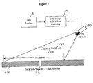
- the track imaging camera 6 provides high quality images of the track ahead of the train, which are used to check the alignment of track sections and other aspects of general track condition. This will be referred to as the Track Imaging Method and will be described with reference to Figure 5 later.
- the basic outline of this technique is shown schematically in Figure 2.
- the output from a convenient continuous wave/illumination (CW) laser source 20 is employed.
- CW continuous wave/illumination
- the output from the 2 nd harmonic of a Nd:YAG laser (intracavity frequency doubled) at 532 nm (green) would provide suitable power/photon flux, and would be a relatively robust system for this application (other sources at other wavelengths are available but will not be discussed here).
- the laser output light 22 from the laser source 20 is expanded by use of a single beam expander lens 24 (or multiple telescopic optics) to fill the side view of the track 28.
- a single beam expander lens 24 or multiple telescopic optics
- Any photons that penetrate the track through a crack or fissure, as shown in Figure 2 by the path taken by the beam 26 through rail track cross section 28, are collected by a telescopic optical system comprising telescopic collection lenses 32 and 34 (though other arrangements of one or more lenses are, of course, possible), and focused onto the front plate of a suitable PMT 38 sensitive to the laser output wavelength of the laser source 20.
- Such a PMT will provide signal amplifications of >10 6 per photon so that even minute light levels exiting the smallest hairline cracks are easily detected.
- a narrow band pass optical filter 36 is placed between the collection optics comprising lenses 32 and 34 and the PMT 38 to reject any background light of wavelengths other than the laser source (for example ⁇ 20 nm; 512 ⁇ 532>552 nm if a Nd:YAG laser is employed).
- Standard digital photon counting techniques are employed to minimize background noise levels to improve the detection sensitivity.
- Scattered light from the laser source 20 is prevented from entering the PMT detector 38 by use of suitable light baffles 30 and, as exemplified by Figure 2, it is relatively simple to prevent light spillage over the top of the rail track.
- the digital signal from the PMT 38 is continuously recorded on a PC 10 as a function of GPS time (GMT) and positional data received from the GPS receiver 8 to provide easy and precise locations of any cracks detected.
- the PC employs standard data logging techniques with milli- or micro-second time-resolution per measurement, which require minimal PC hard-drive memory allocation.
- the alignment of the illumination laser 20 and the collection/detection system comprising lenses 32 and 34, filter 36 and PMT 38. It is possible that light from the laser could directly enter the detector through a well-developed crack/fissure. In some cases it is useful to ensure that light from the laser can never directly impinge upon the detector, since this may cause damage to the detector. In some arrangements of the invention, this can be overcome by employing a sufficient angle between laser source 20 and the collection/detection system to prevent the scenario above whilst maintaining efficient collection of photons penetrating the track.
- the tracks are made up of sections, and there can be a significant gap between adjacent sections through which the laser illumination light might pass directly. As above, it may be preferable to reduce the risk of the light directly hitting the detector, and in some examples this is also achieved by viewing angle adjustments (although other techniques are also possible, such as only enabling the detector on rail sections).
- the optical system is configured in such a manner so as to allow detection of some of this light to demarcate the individual sections of track in the data log. The signal from this light which passes through the gaps in the track will be much greater than light which passes through cracks.
- an intensified CCD video camera could be employed to image the light penetrating the track, and the crack's dimensions could then be extracted from the image.
- the signal amplification with even an intensified CCD camera is orders of magnitude lower than with a PMT, and therefore hairline cracks might not be observed.
- Figure 3 shows an alternative example in which a different probing geometry is used.
- the laser source 20' and beam expander lens 24' are arranged so as to illuminate the top of the rail 28'.
- the light baffles 30' are arranged so as to avoid stray light from the laser source reaching the detectors 38'a and 38'b, which are mounted so as to detect light passing through cracks/fissures in the track 28' and exiting the track on either side.
- the Penetration Method can normally only detect cracks/fissures that run from one side-on surface of the track to the other.
- the Back-Scatter method seeks to detect cracks/fissures which do not penetrate the track entirely. These partial cracks are potentially hazardous in themselves, and may develop into full cracks.
- laser source and camera are also possible; for example the side and top of a section of track could be imaged in a single image given suitable illumination and viewing angles.
- the back-scatter images are recorded on a PC 10 as a function of GPS time and position as received by a GPS receiver 8.
- the images can be analysed on-the-fly via fast DSP techniques or the images/GPS data can be transferred to a computer at the end of the train journey for off-line analysis.
- MVS machine vision software
- cracks or fissures are thought to be longer than they are wide, and thus the width would be the critical observable.
- As a rough estimate of crack width detection limit consider a moderate camera resolution of 1000x1000 pixels (higher resolution is easily achievable) which images a track area of 10 cm 2 ; thus an individual pixel will relate to a crack width of 1 / 10 mm. Therefore, as a conservative estimate, the system is expected to detect cracks which are > 1 / 10 mm in width.
- the detection limit for cracks may be around 1 ⁇ 4 mm in width.
- the camera 70 is mounted at such a vertical height and viewing angle so as to provide an effective field of view 72 of e.g. a 10 metre section of the track 74.
- This field of view will enable images of the entire track to be obtained including gaps 76 between sections of track.
- the tracks and the gaps between the track sections can be isolated by MVS and used as a reference point to calculate the track alignment parameters. This can be compared automatically with critical tolerances supplied by track specialists to determine when the alignment exceeds these tolerance limits. The analysis of the information resulting from use of the Track Imaging Method will be described with reference to Figure 10 later.
- the GPS system is employed to measure the speed of the train and automatically adjust the rate of the camera imaging, meaning that a lower imaging rate is used at slower speed.
- an alert feature can be provided, whereby on identification of a fault or flaw, a notification is sent.
- This notification may include data gathered about the flaw, including images of the flaw.
- the notification may be sent to a central monitoring station, for example using wireless communications, where appropriate action may be taken.
- the data obtained using the penetration method comprises a series of intensity values of laser light detected by the PMT detector at any given point along the track.
- each value is classified to determine whether it corresponds to an unbroken track segment, a crack, or a gap or joining plate between adjacent track sections. If the outcome of the classification indicates a crack (decision step 102), then the information relating to the crack is recorded in step 104.
- Autonomous MVS may be employed either on-the-fly or off-line to analyze the image data from the CCD cameras to detect cracks/fissures in back-scattered images and the track alignment in track imaging images.
- images can be analyzed very rapidly via a computer, removing the need for slow human visual analysis, which is prone to error.
- This process is facilitated as the observable shapes are known, particularly so in the case of the tracks; they are essentially long rectangular shapes which may be curved or have kinks. These shapes are easy to approximate mathematically so that the MVS can fit the observed track images with these shapes and determine the "goodness" of the fit.
- the section of track is well represented mathematically.
- the next step is to compare the mathematical shapes of the tracks at both sides of the gap between two track sections.
- the shapes of the cracks/fissure are not as well defined as the predictable regularity of the rail tracks.
- a neural network can be trained to be sensitive to such shapes defined by brightness levels.
- the cracks/fissures are selected from the background light intensity. Then their length and width (overall shape) can be extracted accurately from the image, since the track coverage per pixel will be known (for example, 1 pixel ⁇ 1 / 10 mm 2 ).
- each new crack's features can be referenced to assess whether the crack is serious or negligible, or whether it should be monitored in the future to see how it develops.
- This database can be constructed from experimental observations of the surface and bulk characteristic of a wide range of cracks, and would be an excellent diagnostic reference. Indeed, the ability to monitor the development of cracks over a period of time is an important feature of the device; the GPS data can provide the location of each crack/fissure to be monitored.
- GPS and its variants do not yet provide sufficient accuracy to exactly locate a crack or other flaw. It is thought that Differential GPS, when used on a moving train, would provide positional information accurate to within a few metres. If several cracks or flaws are present in close proximity to each other, GPS may therefore not provide sufficient accuracy to distinguish between them. This, however, may be overcome by using features of the crack or flaw, such as its dimensions, in identifying a crack or flaw once an approximate location has been established from GPS data.
- the identification of cracks/fissures from the images produced by the back-scatter method will now be described with reference to Figure 7.
- the gray-scale image of a section of track is pre-processed in step 120 in order to separate dark features in the image from the background.
- a classification step 122 determines whether the image contains a feature indicative of a crack.
- the classification step is preferably implemented using an image classification algorithm.
- the image classification algorithm is based on a neural network, for example a standard three-layer back-propagation network, which can be trained from existing images of rail sections with and without cracks.
- the image classification algorithm should be able to distinguish between cracks and other features (such as gaps and joining plates between rails, and leaves and other debris).
- the dimensions of the feature are extracted from the image in step 126.
- a further classification step 128 determines the type and severity of crack represented by the feature. In one example, this is achieved by comparing the dimensions of the feature to an empirical database of known crack types. In another example, a neural-network based image classification algorithm can be used. Finally in step 130, all information regarding the crack is recorded.
- the classification steps 122 and 128 can be combined into one classification step. In that case, rather than first deciding whether a crack is present and then determining its type, the new classification step would have as its possible outcomes the different types of cracks as well as an outcome for when no crack is present.
- the pre-processing step 120 will now be described in more detail, and three possible examples will be described.
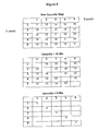
- Each image is made up of an X-Y grid of pixels, e.g. 1000x1000 which translates to 10 6 pixels in total. It is assumed that a crack will be discernable as a less intense or "dark/black" region of this X-Y pixel space. Since the image is monochrome its intensity can be treated at the 8-bit level, thus an individual pixel has an X-Y position register and an 8-bit intensity value, which is treated as a third Z-coordinate. Thus, the 2D image is treated in 3D space, the 3 rd dimension being the intensity value (X-Y position register, and Z intensity register). Further, it may be considered also as a 2D array of intensity values.
- This method requires a single iteration; it just takes the raw intensity map and performs the "binning" for every pixel. Thus the crack's pixellated dimensions are extracted.
- the first derivative of the 3D intensity map provides a measure of the slope or gradient of the surface. By definition, if the first derivative is zero, then there is no slope or gradient and that region of the surface is flat (or of uniform intensity). Thus, non-zero first derivative values within the X-Y grid indicate sloped regions, that is to say cracks.
- the second derivative of the 3D intensity map provides a measure of the rate of change of the slope, and its sign can be used to confirm that the sloping regions do indeed form troughs or cracks (as opposed to anomalous maxima).
- intensity f (x, y)
- intensity is the 8-bit pixel intensity value in the Z-plane
- x and y are the position registers of the pixels in the X- and Y- planes. The differentiation is carried out with respect to x and y.
- the algorithm differentiates the intensity with respect to x and y and produces another 3D surface where the Z-coordinate is a numerical representation of "slope". Uniform intensity regions will be zero on this new surface and troughs/cracks will be non-zero.
- the algorithm selects the non-zero values, subjects them to the second derivative test to confirm a minimum, and stores the X-Y coordinates of these regions. Thus the crack's pixellated dimensions are extracted. Again this is a non-iterative approach.
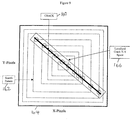
- a search technique can be applied. Instead of processing every pixel in the X-Y grid, an initial search pattern may be followed which is intended to find only small parts of the crack in X-Y space and use a simple interpolation method to join these parts together and thus localize the general position (X-Y area) of the crack.
- the same differential calculus is employed as above to locate minima in the 3D intensity surface. With the crack located, full pixel-by-pixel analysis of the localized area can be performed. This is illustrated schematically in Figure 9.
- the crack 160 is shown as a bold black line, and the search pattern 162 is shown as a dotted line.
- the width of the search pattern may be several pixels to allow sufficient resolution to isolate parts of the crack a few pixels in length. Thus the search only covers a small area of the total X-Y space 164 of the 3D intensity surface. Parts of the crack are isolated (circles in Figure 9, X-Y locations) and then an interpolation is performed to join up these parts to form a line. The line is then used to construct the "localized crack X-Y space" 166 shown in Figure 9.
- This localized X-Y space is then analysed as above on a pixel-by-pixel basis to obtain the X-Y coordinates of the pixels which represent the crack.
- This may allow this technique to be employed for real-time, in-situ track analysis.
- the search pattern can be of any shape but must be sufficiently "tight" to detect cracks which are relatively short.
- eleven points represented by circles
- At the extreme, at least two points on a crack are required for the interpolation. This places restrictions on the tightness of the search, and several iterations of the algorithm may be required with increasing tightness of search pattern to find cracks.
- a feature identification step 180 features that could represent the track in the image are extracted from the image. This can be achieved by the use of a standard edge detection algorithm, for example Robert's Cross edge detection algorithm or the Canny edge detector.
- a mathematical representation of these features is calculated (the details of this step depend on the edge detection algorithm used).
- a selection step 184 identifies those features representing actual segments of track; i.e. in this example rails or rail sections. This can be achieved by using previous knowledge of the expected features; alternatively, a neural-network based classification algorithm is used to identify those features relating to track segments.
- step 186 adjoining track segments are identified (where there may be joins or gaps between two rails).
- step 188 the mathematical representations of two adjoining segments are compared and the alignment between the two is calculated. The calculated alignment parameters are then compared in step 190 against tolerance limits predefined by experts to determine if an alignment problem exists.
- a mount may be used which is capable of providing sufficient vibrational damping to maintain both the pointing accuracy of the illumination lasers and the geometry of the collection optics and imaging devices. Furthermore, damage to the electronic detection devices can be avoided by using suitable field-tested "flight-hardware" housings.
- the lasers and optics can be protected from any flying stones or other debris. It may be useful to prepare the track surface prior to probing by cleaning off any debris such as soil or leaves that may be present on the track. This can be achieved by using a brush or other cleaning device mounted up-track from the detectors.
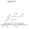
- Figure 11 shows an example of the apparatus as mounted on a train locomotive 200.
- a track imaging camera is mounted at the front of the locomotive 200.
- the full and partial crack sensors are mounted together as sensing apparatus 204 underneath the front of the locomotive, close to the rail 210.
- a track cleaning device 212 is mounted in front of the sensing apparatus 204. Examples of suitable cleaning devices include air jets, water jets, vacuum cleaners and brushes, as well as suitable combinations of such devices.
- a PC 206 is provided inside the driver's cabin.
- a GPS receiver 208 is mounted in a position suitable for the reception of GPS data, in this example on top of the locomotive.
- the track cleaning device 212 at the front of the locomotive clears the rail of debris, for example leaves or dirt.
- the sensing apparatus 204 is mounted in a vibration-dampened casing which also protects the sensors from other debris, for example flying stones.
- sensing apparatus 204, track imaging camera 202 and cleaning device 212 are provided in duplicate; e.g. one of each is provided per rail.
- any or all of these features can be provided in a detachable manner, enabling them to be detached from one side of the vehicle and remounted on the other; or are installed so that they can be moved from one rail to the other.
- Another example of a possible arrangement is to provide these aspects for one rail only on each locomotive. If the locomotives at either end of the train have these aspects provided for different rails, then both rails can be inspected; one rail on the outward journey and one on the return journey. There are, of course, other possible arrangements of these or any of the other features.
- the cleaning device 212 clears the track ahead of the vehicle.
- Sensing apparatus 204 and track imaging camera 202 gather information and transmit the information to PC 206, which stores the information together with GPS data from GPS receiver 208.
- the data can then be transferred from PC 206 to an external computer for analysis, or, as previously discussed, the analysis may be performed during the journey given a suitably equipped PC.
- some or all of the information gathered during the inspection of the track and some or all of the results of any of the above analysis methods can be retained in a database for future reference. This makes it possible to compare information and analysis results from a later inspection of the same section of track with the original information and analysis results. Flaws in the track can then be monitored over time; for example, cracks can be monitored to determine if they have grown. Also, such a database provides an extensive log of the condition of any inspected section of track. Over time, it is possible to build up a comprehensive database of the condition of the entire track in a rail network.
- the devices and methods outlined above are not restricted in application to rail track inspection. They may also be applied to transport systems other than railways, for example, to monorails, cable cars or roller coasters.
- the devices and methods outlined above can also be applied to any context where cracks/fissures are observed in bulk materials.
- the device could be condensed into a hand-held device for inspection of the condition of metal structures from bridges to electrical cable support systems. It is possible that overhead electrical cables could be inspected by a small device that propels itself along the cable and relays the data obtained via a wireless communication link to a remote computer.
- the bulk material is not restricted to metal, and the techniques could be applied to concrete or plastic structures. It could be used on production lines to test for defects in manufactured items susceptible to cracking. Finally, it could be employed on the roads to identify and accurately locate potholes or other defects.
Landscapes
- Engineering & Computer Science (AREA)
- Mechanical Engineering (AREA)
- Investigating Materials By The Use Of Optical Means Adapted For Particular Applications (AREA)
- Length Measuring Devices By Optical Means (AREA)
Applications Claiming Priority (2)
| Application Number | Priority Date | Filing Date | Title |
|---|---|---|---|
| GB0104166A GB2372315A (en) | 2001-02-20 | 2001-02-20 | Determining the track condition in a transport system |
| GB0104166 | 2001-02-20 |
Publications (1)
| Publication Number | Publication Date |
|---|---|
| EP1236634A1 true EP1236634A1 (de) | 2002-09-04 |
Family
ID=9909132
Family Applications (1)
| Application Number | Title | Priority Date | Filing Date |
|---|---|---|---|
| EP02251176A Withdrawn EP1236634A1 (de) | 2001-02-20 | 2002-02-20 | Verfahren und Vorrichtung zur Feststellung des Zustandes eines Gleises |
Country Status (2)
| Country | Link |
|---|---|
| EP (1) | EP1236634A1 (de) |
| GB (1) | GB2372315A (de) |
Cited By (42)
| Publication number | Priority date | Publication date | Assignee | Title |
|---|---|---|---|---|
| WO2005070743A1 (en) * | 2004-01-26 | 2005-08-04 | Force Technology | Detecting rail defects |
| DE102006026048A1 (de) * | 2006-06-01 | 2007-12-20 | Gbm Wiebe Gleisbaumaschinen Gmbh | GPS gestütztes, kontinuierliches Trassenerkundungssystem mit Multisensorik |
| EP1970279A1 (de) * | 2007-03-12 | 2008-09-17 | Strukton Railinfra Installatietechniek B.V. | Kameraeinheit zur Überwachung einer Gleisanlage |
| EP1970278A1 (de) * | 2007-03-12 | 2008-09-17 | Strukton Railinfra Installatietechniek B.V. | Verfahren und Anordnung zur Vermessung eines Gleisabschnitts |
| WO2008144163A1 (en) * | 2007-05-18 | 2008-11-27 | General Electric Company | System and method for capturing an image of a vicinity at an end of a rail vehicle |
| WO2009080070A1 (en) * | 2007-12-20 | 2009-07-02 | Tomtom International B.V. | Improved navigation device and method |
| CN101769877B (zh) * | 2008-12-26 | 2011-07-20 | 中国铁道科学研究院基础设施检测研究所 | 轨道表面擦伤检测系统 |
| CN102565068A (zh) * | 2011-12-12 | 2012-07-11 | 关持循 | 一种钢轨损伤自动检测装置 |
| EP2463175A3 (de) * | 2010-12-13 | 2012-08-15 | AIT Austrian Institute of Technology GmbH | Verfahren zum Auffinden von Oberflächenfehlern |
| US8412393B2 (en) | 2008-07-01 | 2013-04-02 | General Electric Company | Apparatus and method for monitoring of infrastructure condition |
| CN103863357A (zh) * | 2014-03-21 | 2014-06-18 | 杭州海聚动力科技有限公司 | 一种轨道交通接触轨测量装置及测量方法 |
| WO2014163864A1 (en) * | 2013-03-12 | 2014-10-09 | Wabtec Holding Corp. | System, method, and apparatus to detect and report track structure defects |
| US8913131B2 (en) | 2002-06-04 | 2014-12-16 | General Electric Company | Locomotive wireless video recorder and recording system |
| US9481385B2 (en) | 2014-01-09 | 2016-11-01 | General Electric Company | Systems and methods for predictive maintenance of crossings |
| CN106274980A (zh) * | 2016-09-28 | 2017-01-04 | 成都奥克特科技有限公司 | 基于激光监测的轨道状态在线监测方法 |
| GB2542115A (en) * | 2015-09-03 | 2017-03-15 | Rail Vision Europe Ltd | Rail track asset survey system |
| CN106794853A (zh) * | 2014-08-05 | 2017-05-31 | 帕纳塞克公司 | 正向列车控制系统以及用于其的装置 |
| US9873442B2 (en) | 2002-06-04 | 2018-01-23 | General Electric Company | Aerial camera system and method for identifying route-related hazards |
| US9875414B2 (en) | 2014-04-15 | 2018-01-23 | General Electric Company | Route damage prediction system and method |
| CN108099956A (zh) * | 2017-12-14 | 2018-06-01 | 西北铁道电子股份有限公司 | 机车调车装置、方法和双目摄像机的夹角确定方法 |
| US10006877B2 (en) | 2014-08-20 | 2018-06-26 | General Electric Company | Route examining system and method |
| CN108334908A (zh) * | 2018-03-07 | 2018-07-27 | 中国铁道科学研究院 | 铁路钢轨伤损检测方法及装置 |
| US10049298B2 (en) | 2014-02-17 | 2018-08-14 | General Electric Company | Vehicle image data management system and method |
| CN109305179A (zh) * | 2017-07-26 | 2019-02-05 | 中国铁道科学研究院集团有限公司 | 铁路线路设备外观巡检系统 |
| US10501102B2 (en) | 2017-02-06 | 2019-12-10 | Avante International Technology, Inc. | Positive train control system and apparatus employing RFID devices |
| CN110588712A (zh) * | 2019-10-09 | 2019-12-20 | 哈尔滨市科佳通用机电股份有限公司 | 一种基于3d信息的车载铁路路轨检测系统 |
| US10518791B2 (en) | 2015-10-20 | 2019-12-31 | Sameer Singh | Integrated rail and track condition monitoring system with imaging and inertial sensors |
| WO2020102297A1 (en) | 2018-11-15 | 2020-05-22 | Avante International Technology, Inc. | Image-based monitoring and detection of track/rail faults |
| DE102013216892B4 (de) * | 2012-09-12 | 2020-08-13 | International Business Machines Corporation | Standortbestimmung für ein Objekt unter Verwendung von visuellen Daten |
| US11124207B2 (en) | 2014-03-18 | 2021-09-21 | Transportation Ip Holdings, Llc | Optical route examination system and method |
| US11196981B2 (en) | 2015-02-20 | 2021-12-07 | Tetra Tech, Inc. | 3D track assessment apparatus and method |
| US11305799B2 (en) | 2018-06-01 | 2022-04-19 | Tetra Tech, Inc. | Debris deflection and removal method for an apparatus and method for gathering data from sensors oriented at an oblique angle relative to a railway track |
| US11377130B2 (en) | 2018-06-01 | 2022-07-05 | Tetra Tech, Inc. | Autonomous track assessment system |
| US11673590B2 (en) | 2017-08-17 | 2023-06-13 | Robert Hydro | Inspection system for amusement rides having tracks |
| CN116461563A (zh) * | 2022-01-20 | 2023-07-21 | 株式会社东芝 | 铁路线路检测装置以及程序 |
| US11782160B2 (en) | 2019-05-16 | 2023-10-10 | Tetra Tech, Inc. | System and method for generating and interpreting point clouds of a rail corridor along a survey path |
| CN117141547A (zh) * | 2023-05-04 | 2023-12-01 | 苏州智轨科技有限公司 | 一种车载轨道质量检测装置及检测系统 |
| CN117197136A (zh) * | 2023-11-06 | 2023-12-08 | 中数智科(杭州)科技有限公司 | 跨座式单轨轨道梁损伤检测定位系统、方法和存储介质 |
| US11861819B2 (en) | 2018-11-20 | 2024-01-02 | Bnsf Railway Company | Systems and methods for calibrating image capturing modules |
| CN117944734A (zh) * | 2024-03-26 | 2024-04-30 | 中铁第四勘察设计院集团有限公司 | 基于数据外循环与监测内循环的钢轨状态监测方法及系统 |
| US12033312B2 (en) | 2018-11-20 | 2024-07-09 | Bnsf Railway Company | Systems and methods for determining defects in physical objects |
| US12367570B2 (en) | 2022-09-15 | 2025-07-22 | Bnsf Railway Company | System and method for railroad track geometry measurement |
Families Citing this family (10)
| Publication number | Priority date | Publication date | Assignee | Title |
|---|---|---|---|---|
| GB2412261A (en) * | 2004-03-17 | 2005-09-21 | Laser Rail Ltd | Apparatus for determining the profile of structures alongside railway tracks |
| WO2005120924A1 (en) * | 2004-06-11 | 2005-12-22 | Stratech Systems Limited | Method and system for rail track scanning and foreign object detection |
| BRPI0817039A2 (pt) | 2007-08-24 | 2015-07-21 | Stratech Systems Ltd | Sistema e método de vigilância de pista de pouso e decolagem |
| US11538256B2 (en) | 2017-09-12 | 2022-12-27 | Rowan University | Systems and methods for data collection and performance monitoring of transportation infrastructure |
| CN108535414B (zh) * | 2018-04-03 | 2020-01-10 | 北京戴纳实验科技有限公司 | 轨道式巡检系统 |
| CN109668896A (zh) * | 2018-12-19 | 2019-04-23 | 成都精工华耀科技有限公司 | 一种接触网刚性支撑装置缺陷检测分时全景成像系统 |
| DE102019212261A1 (de) * | 2019-08-15 | 2021-02-18 | Siemens Mobility GmbH | Verfahren, Vorrichtung und Schienenfahrzeug |
| US11834082B2 (en) | 2019-09-18 | 2023-12-05 | Progress Rail Services Corporation | Rail buckle detection and risk prediction |
| CN113085948B (zh) * | 2021-06-09 | 2021-10-19 | 成都国铁电气设备有限公司 | 一种轨道综合检测系统 |
| CN114897803A (zh) * | 2022-04-26 | 2022-08-12 | 中国电信集团工会上海市委员会 | 基于无人机和边缘计算的外墙裂缝检测方法和系统 |
Citations (5)
| Publication number | Priority date | Publication date | Assignee | Title |
|---|---|---|---|---|
| JPH0720064A (ja) * | 1993-06-30 | 1995-01-24 | Nippon Steel Corp | 反射赤外法による敷設レール疲労損傷評価法その装置 |
| US5570431A (en) * | 1993-10-20 | 1996-10-29 | Societe Nationale D'etude Et De Construction De Moteurs D'aviation "Snecma" | Process and apparatus for automatically characterizing, optimizing and checking a crack detection analysis method |
| GB2305796A (en) * | 1995-09-26 | 1997-04-16 | London Underground Ltd | Monitoring track condition |
| US6044698A (en) * | 1996-04-01 | 2000-04-04 | Cairo Systems, Inc. | Method and apparatus including accelerometer and tilt sensor for detecting railway anomalies |
| US6064428A (en) * | 1996-08-05 | 2000-05-16 | National Railroad Passenger Corporation | Automated track inspection vehicle and method |
Family Cites Families (5)
| Publication number | Priority date | Publication date | Assignee | Title |
|---|---|---|---|---|
| JPS6356087A (ja) * | 1986-08-26 | 1988-03-10 | Omron Tateisi Electronics Co | 軌条検査方法 |
| JPH0815181A (ja) * | 1994-06-30 | 1996-01-19 | East Japan Railway Co | レール面探傷装置 |
| US5578758A (en) * | 1995-06-21 | 1996-11-26 | Pandrol Jackson Technologies, Inc. | Rail investigating ultrasonic transducer |
| IT1299784B1 (it) * | 1998-04-27 | 2000-04-04 | Azienda Trasporti Municipali M | Metodo ed apparato per rilevare le anomalie di armamenti ferroviari e tranviari |
| DE19957494C1 (de) * | 1999-11-19 | 2001-08-23 | Deutsch Zentr Luft & Raumfahrt | Verfahren und Vorrichtung zur Inspektion von Schienen und Gleisbett |
-
2001
- 2001-02-20 GB GB0104166A patent/GB2372315A/en not_active Withdrawn
-
2002
- 2002-02-20 EP EP02251176A patent/EP1236634A1/de not_active Withdrawn
Patent Citations (5)
| Publication number | Priority date | Publication date | Assignee | Title |
|---|---|---|---|---|
| JPH0720064A (ja) * | 1993-06-30 | 1995-01-24 | Nippon Steel Corp | 反射赤外法による敷設レール疲労損傷評価法その装置 |
| US5570431A (en) * | 1993-10-20 | 1996-10-29 | Societe Nationale D'etude Et De Construction De Moteurs D'aviation "Snecma" | Process and apparatus for automatically characterizing, optimizing and checking a crack detection analysis method |
| GB2305796A (en) * | 1995-09-26 | 1997-04-16 | London Underground Ltd | Monitoring track condition |
| US6044698A (en) * | 1996-04-01 | 2000-04-04 | Cairo Systems, Inc. | Method and apparatus including accelerometer and tilt sensor for detecting railway anomalies |
| US6064428A (en) * | 1996-08-05 | 2000-05-16 | National Railroad Passenger Corporation | Automated track inspection vehicle and method |
Non-Patent Citations (1)
| Title |
|---|
| PATENT ABSTRACTS OF JAPAN * |
Cited By (64)
| Publication number | Priority date | Publication date | Assignee | Title |
|---|---|---|---|---|
| US8913131B2 (en) | 2002-06-04 | 2014-12-16 | General Electric Company | Locomotive wireless video recorder and recording system |
| US9873442B2 (en) | 2002-06-04 | 2018-01-23 | General Electric Company | Aerial camera system and method for identifying route-related hazards |
| US7516662B2 (en) | 2004-01-26 | 2009-04-14 | Force Technology | Detecting rail defects |
| WO2005070743A1 (en) * | 2004-01-26 | 2005-08-04 | Force Technology | Detecting rail defects |
| DE102006026048A1 (de) * | 2006-06-01 | 2007-12-20 | Gbm Wiebe Gleisbaumaschinen Gmbh | GPS gestütztes, kontinuierliches Trassenerkundungssystem mit Multisensorik |
| EP1970279A1 (de) * | 2007-03-12 | 2008-09-17 | Strukton Railinfra Installatietechniek B.V. | Kameraeinheit zur Überwachung einer Gleisanlage |
| EP1970278A1 (de) * | 2007-03-12 | 2008-09-17 | Strukton Railinfra Installatietechniek B.V. | Verfahren und Anordnung zur Vermessung eines Gleisabschnitts |
| WO2008144163A1 (en) * | 2007-05-18 | 2008-11-27 | General Electric Company | System and method for capturing an image of a vicinity at an end of a rail vehicle |
| NL2002105C2 (en) * | 2007-12-20 | 2011-04-05 | Tomtom Int Bv | IMPROVED NAVIGATION DEVICE AND METHOD. |
| WO2009080070A1 (en) * | 2007-12-20 | 2009-07-02 | Tomtom International B.V. | Improved navigation device and method |
| US8412393B2 (en) | 2008-07-01 | 2013-04-02 | General Electric Company | Apparatus and method for monitoring of infrastructure condition |
| CN101769877B (zh) * | 2008-12-26 | 2011-07-20 | 中国铁道科学研究院基础设施检测研究所 | 轨道表面擦伤检测系统 |
| EP2463175A3 (de) * | 2010-12-13 | 2012-08-15 | AIT Austrian Institute of Technology GmbH | Verfahren zum Auffinden von Oberflächenfehlern |
| CN102565068A (zh) * | 2011-12-12 | 2012-07-11 | 关持循 | 一种钢轨损伤自动检测装置 |
| DE102013216892B4 (de) * | 2012-09-12 | 2020-08-13 | International Business Machines Corporation | Standortbestimmung für ein Objekt unter Verwendung von visuellen Daten |
| US8914162B2 (en) | 2013-03-12 | 2014-12-16 | Wabtec Holding Corp. | System, method, and apparatus to detect and report track structure defects |
| WO2014163864A1 (en) * | 2013-03-12 | 2014-10-09 | Wabtec Holding Corp. | System, method, and apparatus to detect and report track structure defects |
| US9481385B2 (en) | 2014-01-09 | 2016-11-01 | General Electric Company | Systems and methods for predictive maintenance of crossings |
| US10049298B2 (en) | 2014-02-17 | 2018-08-14 | General Electric Company | Vehicle image data management system and method |
| US11124207B2 (en) | 2014-03-18 | 2021-09-21 | Transportation Ip Holdings, Llc | Optical route examination system and method |
| CN103863357A (zh) * | 2014-03-21 | 2014-06-18 | 杭州海聚动力科技有限公司 | 一种轨道交通接触轨测量装置及测量方法 |
| US9875414B2 (en) | 2014-04-15 | 2018-01-23 | General Electric Company | Route damage prediction system and method |
| EP3569471A1 (de) * | 2014-08-05 | 2019-11-20 | Avante International Technology, Inc. | Positives zugkontrollsystem und vorrichtung dafür |
| US10315673B2 (en) | 2014-08-05 | 2019-06-11 | Avante International Technology, Inc. | Positive train control system, apparatus and method |
| US10611388B2 (en) | 2014-08-05 | 2020-04-07 | Avante International Technology, Inc. | Positive train control system and method |
| EP3177502A4 (de) * | 2014-08-05 | 2018-04-11 | Panasec Corporation | Positives zugsteuerungssystem und vorrichtung dafür |
| CN106794853A (zh) * | 2014-08-05 | 2017-05-31 | 帕纳塞克公司 | 正向列车控制系统以及用于其的装置 |
| US10006877B2 (en) | 2014-08-20 | 2018-06-26 | General Electric Company | Route examining system and method |
| US11259007B2 (en) | 2015-02-20 | 2022-02-22 | Tetra Tech, Inc. | 3D track assessment method |
| US11196981B2 (en) | 2015-02-20 | 2021-12-07 | Tetra Tech, Inc. | 3D track assessment apparatus and method |
| US11399172B2 (en) | 2015-02-20 | 2022-07-26 | Tetra Tech, Inc. | 3D track assessment apparatus and method |
| US10081376B2 (en) | 2015-09-03 | 2018-09-25 | Sameer Singh | Rail track asset survey system |
| GB2542115B (en) * | 2015-09-03 | 2017-11-15 | Rail Vision Europe Ltd | Rail track asset survey system |
| US10040463B2 (en) | 2015-09-03 | 2018-08-07 | Sameer Singh | Railroad track survey system |
| GB2542115A (en) * | 2015-09-03 | 2017-03-15 | Rail Vision Europe Ltd | Rail track asset survey system |
| US10518791B2 (en) | 2015-10-20 | 2019-12-31 | Sameer Singh | Integrated rail and track condition monitoring system with imaging and inertial sensors |
| CN106274980A (zh) * | 2016-09-28 | 2017-01-04 | 成都奥克特科技有限公司 | 基于激光监测的轨道状态在线监测方法 |
| US10501102B2 (en) | 2017-02-06 | 2019-12-10 | Avante International Technology, Inc. | Positive train control system and apparatus employing RFID devices |
| CN109305179A (zh) * | 2017-07-26 | 2019-02-05 | 中国铁道科学研究院集团有限公司 | 铁路线路设备外观巡检系统 |
| US11673590B2 (en) | 2017-08-17 | 2023-06-13 | Robert Hydro | Inspection system for amusement rides having tracks |
| CN108099956A (zh) * | 2017-12-14 | 2018-06-01 | 西北铁道电子股份有限公司 | 机车调车装置、方法和双目摄像机的夹角确定方法 |
| CN108334908A (zh) * | 2018-03-07 | 2018-07-27 | 中国铁道科学研究院 | 铁路钢轨伤损检测方法及装置 |
| CN108334908B (zh) * | 2018-03-07 | 2022-06-24 | 中国铁道科学研究院集团有限公司 | 铁路钢轨伤损检测方法及装置 |
| US11305799B2 (en) | 2018-06-01 | 2022-04-19 | Tetra Tech, Inc. | Debris deflection and removal method for an apparatus and method for gathering data from sensors oriented at an oblique angle relative to a railway track |
| US11560165B2 (en) | 2018-06-01 | 2023-01-24 | Tetra Tech, Inc. | Apparatus and method for gathering data from sensors oriented at an oblique angle relative to a railway track |
| US11919551B2 (en) | 2018-06-01 | 2024-03-05 | Tetra Tech, Inc. | Apparatus and method for gathering data from sensors oriented at an oblique angle relative to a railway track |
| US11377130B2 (en) | 2018-06-01 | 2022-07-05 | Tetra Tech, Inc. | Autonomous track assessment system |
| US10752271B2 (en) | 2018-11-15 | 2020-08-25 | Avante International Technology, Inc. | Image-based monitoring and detection of track/rail faults |
| US11433931B2 (en) | 2018-11-15 | 2022-09-06 | Avante International Technology, Inc. | Image-based monitoring and detection of track/rail faults |
| US10953899B2 (en) | 2018-11-15 | 2021-03-23 | Avante International Technology, Inc. | Image-based monitoring and detection of track/rail faults |
| WO2020102297A1 (en) | 2018-11-15 | 2020-05-22 | Avante International Technology, Inc. | Image-based monitoring and detection of track/rail faults |
| US12033312B2 (en) | 2018-11-20 | 2024-07-09 | Bnsf Railway Company | Systems and methods for determining defects in physical objects |
| US11861819B2 (en) | 2018-11-20 | 2024-01-02 | Bnsf Railway Company | Systems and methods for calibrating image capturing modules |
| US12249060B2 (en) | 2018-11-20 | 2025-03-11 | Bnsf Railway Company | Systems and methods for calibrating image capturing modules |
| US11782160B2 (en) | 2019-05-16 | 2023-10-10 | Tetra Tech, Inc. | System and method for generating and interpreting point clouds of a rail corridor along a survey path |
| CN110588712A (zh) * | 2019-10-09 | 2019-12-20 | 哈尔滨市科佳通用机电股份有限公司 | 一种基于3d信息的车载铁路路轨检测系统 |
| CN116461563A (zh) * | 2022-01-20 | 2023-07-21 | 株式会社东芝 | 铁路线路检测装置以及程序 |
| EP4223614A1 (de) * | 2022-01-20 | 2023-08-09 | Kabushiki Kaisha Toshiba | Vorrichtung und programm zur erkennung von schienenverzweigungen |
| US12367570B2 (en) | 2022-09-15 | 2025-07-22 | Bnsf Railway Company | System and method for railroad track geometry measurement |
| CN117141547A (zh) * | 2023-05-04 | 2023-12-01 | 苏州智轨科技有限公司 | 一种车载轨道质量检测装置及检测系统 |
| CN117197136B (zh) * | 2023-11-06 | 2024-01-26 | 中数智科(杭州)科技有限公司 | 跨座式单轨轨道梁损伤检测定位系统、方法和存储介质 |
| CN117197136A (zh) * | 2023-11-06 | 2023-12-08 | 中数智科(杭州)科技有限公司 | 跨座式单轨轨道梁损伤检测定位系统、方法和存储介质 |
| CN117944734B (zh) * | 2024-03-26 | 2024-05-28 | 中铁第四勘察设计院集团有限公司 | 基于数据外循环与监测内循环的钢轨状态监测方法及系统 |
| CN117944734A (zh) * | 2024-03-26 | 2024-04-30 | 中铁第四勘察设计院集团有限公司 | 基于数据外循环与监测内循环的钢轨状态监测方法及系统 |
Also Published As
| Publication number | Publication date |
|---|---|
| GB2372315A (en) | 2002-08-21 |
| GB0104166D0 (en) | 2001-04-11 |
Similar Documents
| Publication | Publication Date | Title |
|---|---|---|
| EP1236634A1 (de) | Verfahren und Vorrichtung zur Feststellung des Zustandes eines Gleises | |
| US11142230B2 (en) | Broken wheel detection system | |
| US8547530B2 (en) | System and method to detect foreign objects on a surface | |
| KR101111569B1 (ko) | 궤도차량을 이용한 철도시설물 감시시스템 및 방법 | |
| US7697727B2 (en) | Automated surface distress measurement system | |
| KR101214645B1 (ko) | 트롤리선 마모 측정 장치 | |
| CN102435173B (zh) | 一种基于机器视觉的隧道病害快速调查系统及调查方法 | |
| US7801333B2 (en) | Vision system and a method for scanning a traveling surface to detect surface defects thereof | |
| JP4230395B2 (ja) | 監視移動体 | |
| KR102390003B1 (ko) | 배전선로 애자 연결 점검 시스템 | |
| AU2010248084A1 (en) | System and method for inspecting surfaces using optical wavelength filtering | |
| WO1997007380A2 (en) | Automated system for vehicle condition evaluation | |
| CN107941170A (zh) | 道路检测装置及系统 | |
| CN114572273B (zh) | 一种轨道车辆轮对踏面3d图像检测方法 | |
| CN115035087A (zh) | 一种新型铁路线路图像检测方法及系统 | |
| CN211347924U (zh) | 一种光路垂直分布的道路柴油货车尾气遥测系统 | |
| CN220947814U (zh) | 一种机场跑道巡检无人车 | |
| CN104374375B (zh) | 一种车载应答器外观检测系统 | |
| Nichoha et al. | Development of modern methods and directions of rapid diagnostics of railway tracks defects by television methods | |
| KR20230104333A (ko) | 라이다 및 영상 분석을 통한 도로정보변화 감지 시스템 및 방법 | |
| JP3522256B2 (ja) | 地表状態検出方法、地表状態検出システム、及び地表状態検出装置 | |
| CN115731388A (zh) | 一种道路健康状态一体化快速检测方法及系统 | |
| RU2642687C1 (ru) | Способ комплексной диагностики рельсов | |
| EP1891273B1 (de) | Beobachtungssystem und verfahren zum abtasten einer fahrfläche zur erfassung von oberflächendefekten davon | |
| CN111046765A (zh) | 一种用于高铁的危险预警方法和系统 |
Legal Events
| Date | Code | Title | Description |
|---|---|---|---|
| PUAI | Public reference made under article 153(3) epc to a published international application that has entered the european phase |
Free format text: ORIGINAL CODE: 0009012 |
|
| AK | Designated contracting states |
Kind code of ref document: A1 Designated state(s): AT BE CH CY DE DK ES FI FR GB GR IE IT LI LU MC NL PT SE TR |
|
| AX | Request for extension of the european patent |
Free format text: AL;LT;LV;MK;RO;SI |
|
| AKX | Designation fees paid | ||
| REG | Reference to a national code |
Ref country code: DE Ref legal event code: 8566 |
|
| STAA | Information on the status of an ep patent application or granted ep patent |
Free format text: STATUS: THE APPLICATION IS DEEMED TO BE WITHDRAWN |
|
| 18D | Application deemed to be withdrawn |
Effective date: 20030305 |