EP1236664A2 - Aiguillage de tuyaux notamment pour l'embranchement des courants de matière en vrac - Google Patents
Aiguillage de tuyaux notamment pour l'embranchement des courants de matière en vrac Download PDFInfo
- Publication number
- EP1236664A2 EP1236664A2 EP20020002120 EP02002120A EP1236664A2 EP 1236664 A2 EP1236664 A2 EP 1236664A2 EP 20020002120 EP20020002120 EP 20020002120 EP 02002120 A EP02002120 A EP 02002120A EP 1236664 A2 EP1236664 A2 EP 1236664A2
- Authority
- EP
- European Patent Office
- Prior art keywords
- sealing ring
- housing
- rotary plug
- switch according
- side cover
- Prior art date
- Legal status (The legal status is an assumption and is not a legal conclusion. Google has not performed a legal analysis and makes no representation as to the accuracy of the status listed.)
- Withdrawn
Links
- 239000000463 material Substances 0.000 title description 2
- 238000007789 sealing Methods 0.000 claims abstract description 42
- 239000013590 bulk material Substances 0.000 claims abstract description 3
- 229920001971 elastomer Polymers 0.000 claims description 4
- 239000000806 elastomer Substances 0.000 claims description 4
- 239000002184 metal Substances 0.000 claims description 4
- 230000000712 assembly Effects 0.000 description 3
- 238000000429 assembly Methods 0.000 description 3
- 238000004140 cleaning Methods 0.000 description 2
- 238000012423 maintenance Methods 0.000 description 2
- 230000001419 dependent effect Effects 0.000 description 1
- 230000000694 effects Effects 0.000 description 1
- 238000005516 engineering process Methods 0.000 description 1
- 238000000034 method Methods 0.000 description 1
- 239000004810 polytetrafluoroethylene Substances 0.000 description 1
- 229920001343 polytetrafluoroethylene Polymers 0.000 description 1
Images


Classifications
-
- B—PERFORMING OPERATIONS; TRANSPORTING
- B65—CONVEYING; PACKING; STORING; HANDLING THIN OR FILAMENTARY MATERIAL
- B65G—TRANSPORT OR STORAGE DEVICES, e.g. CONVEYORS FOR LOADING OR TIPPING, SHOP CONVEYOR SYSTEMS OR PNEUMATIC TUBE CONVEYORS
- B65G53/00—Conveying materials in bulk through troughs, pipes or tubes by floating the materials or by flow of gas, liquid or foam
- B65G53/34—Details
- B65G53/52—Adaptations of pipes or tubes
- B65G53/56—Switches
Definitions
- the invention relates to a switch, in particular for branching pneumatically promoted bulk material flows, comprising a housing with input and Output connections by means of a in a recess of the housing rotatably arranged, spherically curved rotary plug optionally with each other can be connected, as well as sealing ring arrangements used in the housing, that lie sealingly on the surface of the rotary plug.
- a generic switch is from the Japanese patent application Hei-4-116005 known. It consists of a housing with detachably attached Flange pieces that form an inlet and two outlet connections. A spherical rotary plug is inserted in a recess in the housing, which is provided with an arched passage. Depending on the position of the rotary plug becomes the input port with one of the output ports brought into flow connection. The recess of the housing is on the side closed by a lid.
- each of a Pipe part with lip seal attached on the front is provided, each of a Pipe part with lip seal attached on the front.
- the lip seal just lies on the spherical surface of the rotary plug and surrounds it Through channel fully in the relevant rotary position.
- the head start of Lid thus fills the remaining distance between the housing and the rotary plug essentially from, with the lead in the area of input and Outlet connections are semicircular excepted. sealing arrangements between rotary plug and housing, of whatever type, are according to this status the technology is not provided. A seal is only made by a corresponding close fit between rotary plug and the housing or Projections of the lid achieved.
- Removing the chick is relatively easy because after removing the chick Lid and the protrusions integrally connected to it on the side can be pulled out. An expansion of the switch from the A pipe system is not required for this.
- the present invention has for its object a sealed switch to provide, in which an exchange of seals and cleaning of Housing recess and rotary plug also possible with little effort is when the switch is installed in a pipe system.
- the housing at least one side cover in the gap between the housing and Has rotary projections protruding, which with a concave arch Inner circumference and a congruent to the housing bore Are provided on the outer circumference and the sealing ring arrangements in the area of Grip half of the inlet and outlet connections.
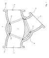
- the bulk diverter shown in FIGS. 1 and 2 consists of a housing 1 with an input port 2, a first aligned with this Outgoing connection 3 and a second branch connection branching off at an angle 4.
- a Rotary plug 6 arranged with a spherically curved outer circumference.
- the Rotary plug 6 has an arcuate through channel 7, which depending on Position of the rotary plug 6 the input port 2 with one of the Outgoing connections 3, 4 connects.
- the rotary plug 6 is via a shaft 8 in Side covers 9, 9 'mounted and adjustable by means of a drive device 10, which are connected in a rotationally fixed manner to one end of the shaft 8 via a plug connection 11 and is attached to the side cover 9.
- the input port 2 and the Outlets 3, 4 are provided with flanges 12 which are integral with the Housing 1 are connected and by means of which the switch with further Delivery lines can be screwed.
- annular projections 13, 13 ' which are integral with the associated side covers 9, 9 'are connected and in the plane of symmetry of Push housing 1 or rotary plug 6 flush against each other.
- the projections 13, 13 ' In the area of the input port 2 and the output ports 3, 4 are the projections 13, 13 'provided with semicircular recesses 14, 14' (see Figure 3).
- sealing ring arrangements 15 in each case embedded, which are fixed in the housing 1 and sealed on the relative to the sealing ring arrangements 15 movable spherical surface of the Rotary plug 6 rest.
- the sealing ring arrangements 15 are each of the associated halves of the recesses 14 and 14 'encompassed on one side. With The sealing ring arrangements rest on their outward-facing end faces plan worked areas in the housing, each orthogonal to the Radius of the recess 5 aligned, the inlet 2 and the outlet connections 3, 4 surrounding level 16 forms, which is to avoid Undercuts extend across the entire width of the housing. In the the remaining areas, the recess 5 is cylindrical.
- the Projections 13, 13 ' are on the outer circumference in these areas corresponding flats 17 provided, which are also over the entire The width of the projections 13, 13 'extend to the side covers 9, 9'.
- Figure 3 shows the switch described above after removing the rotary plug 6. Since this is possible from the side, the switch must be removed from the Pipe system not required. For expansion, the Side cover 9 'detached from housing 1, while the drive side cover 9 can remain on the housing.
- the invention therefore basically also includes Embodiments in which the drive side cover 9 integrally with is connected to the housing.
- the multi-part design shown with the advantage that the drive side of the switch depending on available space in the conveyor system can be changed with little effort can be.
- the side cover 9 ', the rotary plug 6 and the three Sealing ring arrangements 15 as a unit from the recess 5 pulled out. This is easily possible because none of these components Undercuts in the housing 1 or the drive side cover 9 having.
- these are removed detachable fasteners fixed to the side cover.
- one screw 18 each from the outside through the side cover 9 ' and screwed to the associated sealing ring arrangement 15. By loosening the Screws 18 can the sealing ring assemblies 15 subsequently outwards removed and the shaft 8 of the rotary plug 6 pulled out of the side cover 9 ' become.
- FIG. 4 shows different embodiments of the Sealing ring arrangement 15.
- the variant according to FIG. 4 consists of a metal ring 19 with a groove 20, which is preferably produced as a turned part.
- the groove 20 is a relatively rigid sealing ring 22, for example made of PTFE, axially displaceable embedded, which protrudes a little from the groove 20 and through one Elastomer ring 23 is pressed onto the surface of the rotary plug 6.
- metallic springs can be used come.
- the sealing ring 22 is also on the end face of the circumference of the rotary plug 6 adapted, but can also be used to achieve a labyrinth effect Many concentric grooves are provided.
- the one described Sealing ring arrangement 15 ensures that the flow channel in the switch is always bordered by metallic walls.
- the relatively complex Execution of the sealing ring 22 in connection with the elastomer ring 23 is particularly advantageous when conveying powdery bulk materials.
- the sealing ring arrangement 15 consists of two spaced, coaxial arranged metallic pipe sections 24, 25 of different lengths, which are in the range of Contact surface on the rotary plug 6 are arranged offset. Between the inner pipe sections 24 and the outer pipe section 25 is a elastic sealing ring 22 integrally introduced, which to the rotary plug 6 over protrudes the pipe sections 24, 25 and on the surface of the rotary plug 6 is applied.
- the flow channel is also in this relatively inexpensive version essentially surrounded by a metal wall. It is especially for the Suitable for conveying granular bulk goods.
Landscapes
- Engineering & Computer Science (AREA)
- Mechanical Engineering (AREA)
- Switch Cases, Indication, And Locking (AREA)
- Air Transport Of Granular Materials (AREA)
Applications Claiming Priority (2)
| Application Number | Priority Date | Filing Date | Title |
|---|---|---|---|
| DE2001109916 DE10109916C1 (de) | 2001-03-01 | 2001-03-01 | Weiche, insbesondere zum Verzweigen von Schüttgutströmen |
| DE10109916 | 2001-03-01 |
Publications (1)
| Publication Number | Publication Date |
|---|---|
| EP1236664A2 true EP1236664A2 (fr) | 2002-09-04 |
Family
ID=7675962
Family Applications (1)
| Application Number | Title | Priority Date | Filing Date |
|---|---|---|---|
| EP20020002120 Withdrawn EP1236664A2 (fr) | 2001-03-01 | 2002-01-29 | Aiguillage de tuyaux notamment pour l'embranchement des courants de matière en vrac |
Country Status (2)
| Country | Link |
|---|---|
| EP (1) | EP1236664A2 (fr) |
| DE (1) | DE10109916C1 (fr) |
Cited By (1)
| Publication number | Priority date | Publication date | Assignee | Title |
|---|---|---|---|---|
| WO2004026740A1 (fr) * | 2002-09-12 | 2004-04-01 | Zeppelin Silo- Und Apparatetechnik Gmbh | Dispositif de bifurcation, servant notamment a faire bifurquer des flux de matieres en vrac |
Families Citing this family (2)
| Publication number | Priority date | Publication date | Assignee | Title |
|---|---|---|---|---|
| DE102009057650A1 (de) * | 2009-12-09 | 2011-06-16 | GESRA Gerätebau GmbH | Förderrohrweiche |
| CN101934936A (zh) * | 2010-09-03 | 2011-01-05 | 江门市正曦输送机械设备有限公司 | 一种粉末浆料输送装置 |
Family Cites Families (1)
| Publication number | Priority date | Publication date | Assignee | Title |
|---|---|---|---|---|
| DE4439620C2 (de) * | 1994-11-05 | 1998-07-16 | Reimelt Dietrich Kg | Rohrweiche |
-
2001
- 2001-03-01 DE DE2001109916 patent/DE10109916C1/de not_active Expired - Fee Related
-
2002
- 2002-01-29 EP EP20020002120 patent/EP1236664A2/fr not_active Withdrawn
Cited By (2)
| Publication number | Priority date | Publication date | Assignee | Title |
|---|---|---|---|---|
| WO2004026740A1 (fr) * | 2002-09-12 | 2004-04-01 | Zeppelin Silo- Und Apparatetechnik Gmbh | Dispositif de bifurcation, servant notamment a faire bifurquer des flux de matieres en vrac |
| US7278449B2 (en) | 2002-09-12 | 2007-10-09 | Zeppelin Silo- Und Apparatetechnik Gmbh | Switch, especially for branching off bulk material flows |
Also Published As
| Publication number | Publication date |
|---|---|
| DE10109916C1 (de) | 2002-07-25 |
Similar Documents
| Publication | Publication Date | Title |
|---|---|---|
| DE3828693C1 (fr) | ||
| DE69602233T2 (de) | Anbohr-Anschlussstück | |
| DE1288392B (de) | Drehschieber | |
| DE2313983A1 (de) | In eine fluidleitung einschaltbare kupplungseinrichtung zur aufnahme mindestens einer beeinflussungsvorrichtung fuer das fluid | |
| DE3014874A1 (de) | Absperrventil | |
| EP0305821B1 (fr) | Dispositif pour fermer l'embranchement d'un tube | |
| DE69829508T2 (de) | Vorrichtung und verfahren zum montieren eines sattels auf einer druckrohrleitung und dafür geeignetes ventil | |
| EP0696699A1 (fr) | Soupape de vidange | |
| DE10109916C1 (de) | Weiche, insbesondere zum Verzweigen von Schüttgutströmen | |
| DE19542568C2 (de) | Absperrorgan mit einer verschwenkbaren Drehklappe und einer entropieelastischen Ringdichtung | |
| DE3616964C2 (de) | Anschlußverbindungsstück | |
| DE3120115C2 (fr) | ||
| DE4003733C2 (fr) | ||
| DE202022106965U1 (de) | Rohrweiche zur Herstellung einer Verzweigungsstelle in einem pneumatischen Fütterungssystem | |
| DE3149066C2 (de) | Drehdurchführung für Rohrleitungen an einem Lagerzapfen eines schwenkbaren Konverters | |
| DE8524858U1 (de) | Doppeltellerventil | |
| DE3541754C2 (fr) | ||
| DE19925200C1 (de) | Schüttgutweiche | |
| EP0733835A2 (fr) | Système d'étanchéité pour un robinet-vanne | |
| EP0355301A2 (fr) | Vanne d'arrêt | |
| DE3003480A1 (de) | Rueckschlagventil | |
| DE3901466C2 (fr) | ||
| DE202018101406U1 (de) | Drehauswerfer für Fördergut | |
| DE3044513C2 (de) | Kupplung für eine Rohrsteckverbindung | |
| EP0036535B1 (fr) | Accouplement à réparation |
Legal Events
| Date | Code | Title | Description |
|---|---|---|---|
| PUAI | Public reference made under article 153(3) epc to a published international application that has entered the european phase |
Free format text: ORIGINAL CODE: 0009012 |
|
| AK | Designated contracting states |
Kind code of ref document: A2 Designated state(s): AT BE CH CY DE DK ES FI FR GB GR IE IT LI LU MC NL PT SE TR |
|
| AX | Request for extension of the european patent |
Free format text: AL;LT;LV;MK;RO;SI |
|
| STAA | Information on the status of an ep patent application or granted ep patent |
Free format text: STATUS: THE APPLICATION HAS BEEN WITHDRAWN |
|
| 18W | Application withdrawn |
Withdrawal date: 20021108 |