EP1236867B1 - Méthode et dispositif de montage et d'ajustage des aubes de guidage pivotables d'une turbine - Google Patents
Méthode et dispositif de montage et d'ajustage des aubes de guidage pivotables d'une turbine Download PDFInfo
- Publication number
- EP1236867B1 EP1236867B1 EP02004744A EP02004744A EP1236867B1 EP 1236867 B1 EP1236867 B1 EP 1236867B1 EP 02004744 A EP02004744 A EP 02004744A EP 02004744 A EP02004744 A EP 02004744A EP 1236867 B1 EP1236867 B1 EP 1236867B1
- Authority
- EP
- European Patent Office
- Prior art keywords
- nozzle
- vanes
- turbine
- link mechanism
- annular link
- Prior art date
- Legal status (The legal status is an assumption and is not a legal conclusion. Google has not performed a legal analysis and makes no representation as to the accuracy of the status listed.)
- Expired - Lifetime
Links
- 238000000034 method Methods 0.000 title claims abstract description 37
- 239000000470 constituent Substances 0.000 claims abstract description 8
- 230000013011 mating Effects 0.000 claims 8
- 238000005266 casting Methods 0.000 claims 1
- 238000002485 combustion reaction Methods 0.000 description 3
- 238000004519 manufacturing process Methods 0.000 description 3
- 238000010276 construction Methods 0.000 description 2
- 230000000712 assembly Effects 0.000 description 1
- 238000000429 assembly Methods 0.000 description 1
- 238000007796 conventional method Methods 0.000 description 1
- 230000007423 decrease Effects 0.000 description 1
- 230000001419 dependent effect Effects 0.000 description 1
- 239000000463 material Substances 0.000 description 1
Images




Classifications
-
- F—MECHANICAL ENGINEERING; LIGHTING; HEATING; WEAPONS; BLASTING
- F02—COMBUSTION ENGINES; HOT-GAS OR COMBUSTION-PRODUCT ENGINE PLANTS
- F02B—INTERNAL-COMBUSTION PISTON ENGINES; COMBUSTION ENGINES IN GENERAL
- F02B37/00—Engines characterised by provision of pumps driven at least for part of the time by exhaust
- F02B37/12—Control of the pumps
- F02B37/24—Control of the pumps by using pumps or turbines with adjustable guide vanes
-
- F—MECHANICAL ENGINEERING; LIGHTING; HEATING; WEAPONS; BLASTING
- F01—MACHINES OR ENGINES IN GENERAL; ENGINE PLANTS IN GENERAL; STEAM ENGINES
- F01D—NON-POSITIVE DISPLACEMENT MACHINES OR ENGINES, e.g. STEAM TURBINES
- F01D17/00—Regulating or controlling by varying flow
- F01D17/10—Final actuators
- F01D17/12—Final actuators arranged in stator parts
- F01D17/14—Final actuators arranged in stator parts varying effective cross-sectional area of nozzles or guide conduits
- F01D17/16—Final actuators arranged in stator parts varying effective cross-sectional area of nozzles or guide conduits by means of nozzle vanes
- F01D17/165—Final actuators arranged in stator parts varying effective cross-sectional area of nozzles or guide conduits by means of nozzle vanes for radial flow, i.e. the vanes turning around axes which are essentially parallel to the rotor centre line
-
- F—MECHANICAL ENGINEERING; LIGHTING; HEATING; WEAPONS; BLASTING
- F05—INDEXING SCHEMES RELATING TO ENGINES OR PUMPS IN VARIOUS SUBCLASSES OF CLASSES F01-F04
- F05D—INDEXING SCHEME FOR ASPECTS RELATING TO NON-POSITIVE-DISPLACEMENT MACHINES OR ENGINES, GAS-TURBINES OR JET-PROPULSION PLANTS
- F05D2220/00—Application
- F05D2220/40—Application in turbochargers
-
- F—MECHANICAL ENGINEERING; LIGHTING; HEATING; WEAPONS; BLASTING
- F05—INDEXING SCHEMES RELATING TO ENGINES OR PUMPS IN VARIOUS SUBCLASSES OF CLASSES F01-F04
- F05D—INDEXING SCHEME FOR ASPECTS RELATING TO NON-POSITIVE-DISPLACEMENT MACHINES OR ENGINES, GAS-TURBINES OR JET-PROPULSION PLANTS
- F05D2230/00—Manufacture
- F05D2230/60—Assembly methods
- F05D2230/64—Assembly methods using positioning or alignment devices for aligning or centring, e.g. pins
-
- Y—GENERAL TAGGING OF NEW TECHNOLOGICAL DEVELOPMENTS; GENERAL TAGGING OF CROSS-SECTIONAL TECHNOLOGIES SPANNING OVER SEVERAL SECTIONS OF THE IPC; TECHNICAL SUBJECTS COVERED BY FORMER USPC CROSS-REFERENCE ART COLLECTIONS [XRACs] AND DIGESTS
- Y10—TECHNICAL SUBJECTS COVERED BY FORMER USPC
- Y10T—TECHNICAL SUBJECTS COVERED BY FORMER US CLASSIFICATION
- Y10T29/00—Metal working
- Y10T29/49—Method of mechanical manufacture
- Y10T29/49316—Impeller making
- Y10T29/4932—Turbomachine making
Definitions
- the present invention relates to a method and device for assembling and adjusting the adjustable nozzle mechanism of a radial flow turbine used as the supercharger of an internal combustion engine (exhaust turbocharger) and so forth, the turbine being configured so that the actuating gas flows from the spiral scroll formed in the turbine casing to the turbine rotor in the radial direction via a plurality of nozzle vanes of variable wing angle to rotate the turbine rotor.
- a supercharger with such a variable capacity turbine is equipped with an adjustable nozzle mechanism in order to change the turbine capacity.
- the adjustable nozzle mechanism can change the wing angle of the nozzle vanes through rotating the nozzle vanes by means of an annular link mechanism (ring assembly) which is driven to rotate around the rotation center of the turbine rotor by an actuator by way of an actuator rod.
- DE 4 309 636 shows the prior state of the art.
- a jig should be placed in the inner radius of the nozzle vane to perform the setup for perfect closing of the nozzle vane and the ring assembly to be driven for rotations around the turbine rotor shaft.
- the jig therein can be put in contact with the rear edge of the nozzle vane, wherein the stopper pin is mounted after the nozzle vane and the lever plates are welded together upon putting the nozzle vane in contact with the jig in the state that the stopper pin, that is to be fitted into the long slots located at multiple positionsalongthecircumferentialdirectionofthelinkplate, is made non-functional or non-existing, and upon fitting the matching pin into the phase matching hole to finalize the entire ring assembly in the perfect closing phase.
- the setup for perfect closing of the adjustable nozzle mechanism is done by fitting each stopper pin into each long slot provided on the link plate along the circumferential direction and matching the contact angle with the lever plate by contacting the tail end of the nozzle bane with the jig, so variations in setup for perfect closing tend to occur resulting in setup error.
- the perfect closing position of the adjustable nozzle mechanism is influenced by the accuracy of such constituent parts as described above, the adjustment is difficult after assembling turbine.
- the object of this invention is to provide a method and device for assembling and adjusting a variable capacity turbine, which simplifies the assembling and adjustment process of an adjustable nozzle mechanism to reduce man-hours and costs for assembling and adjustment, is capable of setting up the positions of the nozzle vanes of an adjustable nozzle mechanism with good accuracy without influenced by the accuracy in dimension of the constituent parts such as nozzle vanes, annular link assemblies (ring assembly), etc., and is capable of adjusting the adjustable nozzle mechanism whenever necessary even after they are assembled.
- the invention proposes a method according to Claim 1 of and a device according to claim 8 for assembling and adjusting a variable capacity turbine having a plurality of nozzle vanes disposed along the circumferential direction of a turbine rotor in the inner radius side of a spiral scroll formed in a turbine casing and supported for rotation on a supporting part of a nozzle mount.
- the assembling and adjustment procedure is extremely simplified compared with the prior art disclosed on Japanese Patent No.3085210 in which the adjustment of perfect closing position is done in the assembling process of nozzle vanes by use of a plurality of long slots in the link plate, stopperpins, andajig. Therefore, man-hours for assembling and adjustment decreases and accordingly manufacturing costs is reduced.
- reference number 30 is a turbine casing
- 38 is a scroll passage formed in spiral around the circumference section in the turbine casing
- 39 is an exhaust inlet to the scroll passage 38
- 49 is an exhaust gas outlet for letting out the exhaust gas having done expansion work in the turbine wheel 34.
- Reference number 31 is a compressor casing
- 36 is a bearing housing which connects the compressor casing 31 with the turbine casing 30.
- Reference number 34 is a turbine wheel
- 35 is a compressor wheel
- 33 is a turbine rotor shaft connecting the compressor wheel 35 to the turbine wheel 34
- 37 are bearings provided in the bearing housing 36 for supporting the turbine rotor shaft 33.
- Reference number 1 are nozzle vanes which are positioned around the circumferential inlet of the turbine wheel 34 in the inner side of the scroll passage 38 spaced at regular intervals.
- the nozzle pins (see FIG.1 ) formed integral with the nozzle vanes are supported free for rotation in a nozzle mount 4 fixed to the turbine casing 30, and thus the wing angle of the nozzle vanes is able to be changed.
- Reference number 100 is an adjustable nozzle mechanism.
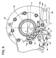
- An actuator drives an actuator rod 40(see FIG.8 ) to rotate a ring assembly 10 (annular link mechanism, see FIG.1 ) around the rotation axis 8 of the turbine rotor shaft 33.
- the nozzle vanes are rotated by the rotation of the ring assembly 10 to be changed in their wing angle.
- the exhaust gas from an internal combustion engine enters into the scroll passage 38 and flows in the nozzle vanes 1 circling along the spiral of the scroll passage 38.
- the exhaust gas flows through the wing space between the nozzle vanes, enters into the turbine wheel 34 from the outer circumference thereof, flows in the radial inward direction expanding while executing work to the turbine wheel 34, and exits from the exhaust outlet 49 in the longitudinal direction.
- the means of assembling and adjusting the adjustable nozzle mechanism of the variable capacity turbine is improved as described hereinafter.
- reference number 10 is a ring assembly comprising a link plate 3 of disk like shape and lever plates 2 connected with the link plate 3 by means of link parts 10a.
- the same number of the link parts 10a and lever plates 2 as that of the nozzle vanes 1 are provided, each corresponding to each nozzle vane, spaced at regular circular intervals as shown in FIG.3 .
- Reference number 03 is a connection part of the link plate 3. As shown in FIG.8 , a drive lever 41 which is connected to an actuator rod 40 is connected to the connection part 03 by means of a connection pin 9 fitted to the connection part.
- Reference number 4 is an annular shape nozzle mount fixed to the turbine casing 30, 5 is a disk like nozzle plate. A number of nozzle supports 7 are provided along the circumferential direction to fix the nozzle plate 5 to the nozzle mount 4.
- the nozzle vanes 1 are disposed inside the nozzle support between the nozzle mount 4 and nozzle plate 5.
- Nozzle pins 6 fixed to the nozzle vanes (or integral with the nozzle vanes) are supported free of rotation by the nozzle mount 4.
- Each nozzle pin 6 fixed to each nozzle vane is fixed to the lever plate 2 at the lower end part thereof by staking at its end part as indicated by reference number 2a.
- the drive lever 41 is supported by the turbine casing 30 at its center part by the support shaft 42.
- An end part of the drive lever 41 is connected to the connection part 03 of the link plate 3 by means of the connection pin 9, and the other end is connected to the actuator rod 40 extending from an actuator not shown in the drawing.
- the drive lever 41 swings around the support shaft 42 according to the reciprocating motion of the actuator rod 40, and the link plate 3 is driven to rotate around the rotation axis 8 of the turbine by means of the connection part 03 of the link plate 3 to which the drive lever 41 is connected.
- the reciprocating movement of the actuator rod 40 and the swing movement of the nozzle vanes are the same as those of the ordinary variable capacity turbines.
- the method of assembling and adjusting the adjustable nozzle mechanism 100 of the variable capacity turbine equipped with the adjustable nozzle mechanism 100 of the construction described above will be explained.
- the plurality of the nozzle vanes 1 are disposed to contact each other in a perfectly closed state and encircled with a belt 11 to be temporarily bound. By this, a number of the nozzle vanes 1 are all set to the perfectly closed state.
- the member for binding the nozzle vanes 1 is not limited to be the belt 11, a string, a rubber member, and the like may be usable as far as it is easy to bind and release the vanes.
- the ring assembly 10 is prepared beforehand by fitting an end side of each of the link parts 10a free for rotation to the link plate 3 and further fitting the upper end part of each of the lever plates 2 free for rotation to the other end of each of the link parts 10a.
- Each of the nozzle vanes 1 is fitted between the nozzle mount 4 and nozzle plate 5, the nozzle mount 4 and nozzle plate 5 are positioned and fixed to the nozzle supports 7 by the conventional method.
- the position of the ring assembly 10 corresponding to the perfect closing position of the nozzle vanes is determined by one of the following two methods.
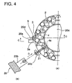
- FIG.4 and FIG.5 represent the first method.
- a radial matching hole 4a is drilled in the nozzle mount 4 at the position apart from the center of the connection pin 9 which is to connect the drive lever 41 (see FIG.8 ) by an angle A as shown in FIG.3 .
- the position of the ring assembly 10 relative to the matching hole 4a of the nozzle mount 4 is determined by use of a jig (A) 20 of which the central angle between the contact face 20d of the contact part 20a and the center of the angle locating part 20b is pre-determined and a rod like jig (B) 21, through inserting the end part of the jig (B) 21 inserted in the angle locating part 20b of the jig (A) into the matching hole 4a and allowing the side face 3a of the connection part 03 of the link plate 3 to contact with the contact face 20d of the jig(A) 20.
- nozzle pins 6 which is integral with the nozzle vanes and supported free for rotation in the nozzle mount 4 are fixed to the lever plates 2 by staking in the holes at the lower end part of the lever plates 2 which constitute the connection parts of the ring assembly 10.
- a staking port ion is indicated in FIG.1 by reference number 2a.
- FIG.6 the second method is represented in FIG.6 , in which a radial matching hole 4a is drilled in the nozzle mount 4 at the position apart from the center of the connection pin 9 by an angle A the same as the case of the first method.
- the position of the ring assembly 10 relative to the matching hole 4a of the nozzle mount 4 is determined by use of a jig(C) 22 of which an arm 22a is provided with a hole 22c at an end part thereof into which said jig (B) 21 inserted and with a groove 22b which is formed so that the head part of the link pin 9 of the link plate 3 (or the connection part 03 shown in FIG.3 ) can be inserted and the center angle between the hole 22c and the groove 22b is pre-determined to be A, by inserting the end part of the jig (B) 21 inserted into the hole 22c of the jig(C) 22 into the matching hole 4a of the nozzle mount 4 and fitting the groove 22b to the head part of the connection pin 9 (or the connection part 03 shown in FIG.3 ).
- the perfect closing positions of all the nozzle vanes 1 are thus determined in the ring assembly 10.
- the adjustment of the perfect closing position after the adjustable nozzle mechanism 100 adjusted as described above is installed into a variable capacity turbine can be done as follows: the nozzle vanes 1 bound with the belt 11 (binding member) to keep the temporarily fixed state are released from the bound state, and the position of the set of the nozzle vanes is adjusted by the adjusting screw 44a and the locking nut 44b of a shutdown side stopper 44 which is provided for limiting the shift of the drive lever 41 connecting the ring assembly 10 to the actuator rod 40 as shown in FIG.8 . This adjustment can be done in the state where the variable capacity turbine is assembled.
- the stopper mechanism provided for setting perfect closing position in the prior art nozzle assembly is unnecessary and omitted, variations in dimensions of the nozzle vanes 1 and the ring assembly can be absorbed, assembling of the nozzle assembly including nozzle vanes 1 is simplified, and the setting of various specifications of the adjustable nozzle mechanism is possible with the same nozzle assembly.
- Reference number 43 is a maximum stopper, wherein the adjustment of the full open position can be done by an adjusting screw 43a and a lock nut 43b of the maximum stopper 43 in the state the adjustable capacity turbine is assembled.
- a plurality of the nozzle vanes 1 are bound temporarily by encircling them with a belt 11 (binding member) capable of easy binding/releasing to fix them in a perfect closed state with the vanes contacting to each other, then the positioning of the nozzle vane 1 side (nozzle assembly) relative to the ring assembly (annular link mechanism) 10 side is done by the first or second method using the jigs (A) and (B), or (B) and (C), and each of the nozzle pins which are fixed to the nozzle vanes to be integral with the vanes is fixed to each lever plate 2 constituting the connection part of the ring assembly by staking, so the adjustment of perfect closing position of the vanes in the nozzle assembling process is unnecessary and the adjustment of the perfect closing position can be done freely by the minimum stopper 44 in the state when the variable capacity turbine is assembled.
- the adjustable nozzle mechanism 100 is set by this simple method in which a plurality of the nozzle vanes 1 are bound by an encircling band 11 (binding member), the relative position of the nozzle assembly to the ring assembly is determined by use of jigs, and each nozzle vane is fixed to each lever plate, and which eliminates the necessity of adjustment of the perfect closing position in nozzle assembling process, the assembling and adjustment procedure is extremely simplified resulting in reduction of man-hours for assembling and adjustment, accordingly manufacturing cost is reduced compared with the prior art according to Japanese Patent No.3085210 in which the adjustment of the perfect closing position is done by use of a plurality of long slots in the link plate, stopper pins and jigs in the nozzle assembling process.
- a plurality of the nozzle vanes 1 are bound by encircling them with the belt 11 to determine the perfect closing position, each nozzle vane is fixed to the lever plate 2, and the adjustment of the perfect closing position is done as a whole by the minimum stopper 44 in the assembled state of the variable capacity turbine, so errors in dimensions of the nozzle assembly including nozzle vanes 1 and the ring assembly in their assembled states can be absorbed. Therefore, the perfect closing position of each nozzle vane is not determined uniquely according to the accuracy of the constituent parts and the setting of the perfect closing position is possible with good accuracy without being influenced by the accuracy in dimensions of the nozzle assembly and ring assembly, contrary to the case of Japanese Patent No.
- variable capacity turbine has the same function as the exhaust brake of a truck and so forth by adjusting the perfect closing position by the minimum stopper 44.
- adjustable nozzle mechanism assembly 100 can be transferred and assembled into the turbine in the state in which a plurality of the nozzle vanes 1 are encircled and bound with the belt 11 and fixed to the supporting parts of the nozzle mount 4, damage to the constituent parts of the nozzle assembly due to vibration or impact is prevented.
- a plurality of nozzle vanes are encircled with a binding member capable of binding/releasing to temporarily fix the vanes in a state where the vanes are perfectly closed with the vanes contacting to each other; then the positioning of the nozzle vane side, i.e. the nozzle assembly side relative to the annular link mechanism side, is performed by use of jigs in the temporarily fixed state; and the driving part of each nozzle vane is fixed to each connection part of the annular link mechanism; so the adjustment of the perfect closing position is unnecessary in the nozzle assembling process, and the adjustment of perfect closing position is possible in the assembled state of the variable capacity turbine.
- the adjustable nozzle mechanism is set by this simple method in which a plurality of the nozzle vanes are bound by an encircling binding member, the relative position of the nozzle assembly to the annular link mechanism is determined by use of jigs, and each nozzle vane is fixed to each lever plate, and which eliminates the necessity of adjustment of perfect closing position in nozzle assembling process, the assembling and adjustment procedure is extremely simplified resulting in reduction of man-hours for assembling and adjustment, accordingly manufacturing cost reduces.
- each nozzle vane is fixed to the lever plate 2, and the adjustment of the perfect closing position is done as a whole by a minimum stopper in the assembled state of the variable capacity turbine, errors in dimensions of the nozzle assembly including nozzle vanes and the ring assembly including the link plate and link parts in their assembled states can be absorbed. Therefore, the setting of the adjustable nozzle mechanism is possible with good accuracy without being influenced by the accuracy in dimensions of the nozzle assembly and ring assembly, and also the adjustable nozzle mechanism is adaptable to various specifications.
- variable capacity turbine has the same function as the exhaust brake of truck and so forth by adjusting the perfect closing position by the minimum stopper.
- the adjustment of the full open position of the nozzle vanes is possible by the maximum stopper in the assembled state of the variable capacity turbine.
- the adjustable nozzle mechanism assembly can be transferred and installed into the turbine in the state in which a plurality of the nozzle vanes are temporarily encircled and bound with the binding member and fixed to the supporting parts of the nozzle mount 4, damage to the constituent parts of the nozzle assembly due to vibration or impact is prevented.
Landscapes
- Engineering & Computer Science (AREA)
- Mechanical Engineering (AREA)
- General Engineering & Computer Science (AREA)
- Chemical & Material Sciences (AREA)
- Combustion & Propulsion (AREA)
- Supercharger (AREA)
- Control Of Turbines (AREA)
- Turbine Rotor Nozzle Sealing (AREA)
- Structures Of Non-Positive Displacement Pumps (AREA)
- Hydraulic Turbines (AREA)
Claims (10)
- Procédé de montage et de réglage d'une turbine à capacité variable comprenant :une pluralité d'aubes de distributeur (1) disposées le long de la direction de la circonférence d'un rotor de turbine du côté du rayon interne d'un élément en spirale (38) formé dans un carter de turbine (30) et supporté de manière à pouvoir tourner sur une partie de support d'une monture de distributeur (4) ;dans lequel le rotor de turbine est supporté dans le carter de turbine (3) de manière à pouvoir tourner autour d'un axe de rotation (8) ; etdans lequel un mécanisme de liaison annulaire (10) est monté de manière à pouvoir tourner par rapport à l'axe de rotation (8) et comporte des parties de connexion (2, 10a) dont chacune est connectée à une partie d'entraînement (6) de chacune desdites aubes de distributeur (1) et à une extrémité de sortie d'un mécanisme de commande (40, 41) ;ledit procédé étant caractérisé par les étapes de :encerclement et attache temporaire de ladite pluralité d'aubes de distributeur (1) dans un état dans lequel les aubes de distributeur (1) sont parfaitement fermées et sont en contact les unes avec les autres avec un élément d'attache (11) qui est capable d'attacher / de libérer lesdites aubes de distributeur (1), et ensuite,fixation de la partie d'entraînement (6) de chaque aube de distributeur (1) sur la partie de connexion respective (2, 10a) du mécanisme de liaison annulaire (10), les aubes de distributeur (1) étant dans l'état de liaison temporaire.
- Procédé selon la revendication 1, dans lequel des axes de distributeur (6) qui constituent ladite partie d'entraînement et qui sont fixées sur ou qui sont intégrées à l'une des aubes de distributeur (1) et qui sont supportés dans ladite monture de distributeur (4) de manière à pouvoir tourner sont fixés sur des plaques de levier (2) des parties de connexion du mécanisme de liaison annulaire (10) par des moyens d'agrafage ou similaires dans l'état d'attache temporaire, les aubes de distributeur (1) étant parfaitement fermées.
- Procédé selon la revendication 1 ou la revendication 2, dans lequel les parties constitutives sont transférées ou montées à l'intérieur de la turbine dans un état où un assemblage de distributeur est temporairement fixé sur la partie de support de ladite monture de distributeur (4) par encerclement et attache des aubes de distributeur (1) grâce à l'élément d'attache (11) dans l'état dans lequel les aubes de distributeur (1) sont parfaitement fermées et sont en contact les unes avec les autres.
- Procédé selon la revendication 2, dans lequel :une partie d'ajustement du côté de l'aube de distributeur (4a) est disposée dans la monture de distributeur (4) ;une partie d'ajustement du côté de la liaison est disposée dans le mécanisme de liaison annulaire (10) ;il est préparé un gabarit (20, 21 ; 21, 22) sur lequel une partie est formée sur un côté d'extrémité destinée à déterminer la position du côté de l'aube de distributeur et sur lequel une partie est formée sur l'autre côté d'extrémité destinée à déterminer la position du côté du mécanisme de liaison annulaire, ladite partie dudit gabarit (20, 21 ; 21, 22) destinée à déterminer la position du côté de l'aube de distributeur est ajustée avec ladite partie d'ajustement du côté de l'aube de distributeur (4a) de ladite monture de distributeur (4) et ladite partie d'ajustement du côté de la liaison est ajustée avec ladite partie destinée à déterminer la position du côté du mécanisme de liaison annulaire, chaque aube de distributeur (1) étant temporairement fixée dans la position de fermeture parfaite ; etla position de fermeture parfaite du côté de l'aube de distributeur et du côté du mécanisme de liaison annulaire est établie en fixant lesdits axes de distributeur (6) sur lesdites plaques de levier (2) par agrafage ou similaire.
- Procédé selon la revendication 4, dans lequel :ladite monture de distributeur (4) comporte un orifice d'ajustement (4a) qui sert de partie d'ajustement du côté de ladite aube de distributeur ;ledit gabarit (20, 21) comporte une saillie en forme d'axe qui sert de dite partie destinée à déterminer la position du côté de l'aube de distributeur et une face de contact (20d) capable d'être en contact avec une face d'une plaque de liaison (3) dudit mécanisme de liaison annulaire (10) qui sert de dite partie destinée à déterminer la position du côté du mécanisme de liaison annulaire.
- Procédé selon la revendication 4, dans lequel :ladite monture de distributeur (4) comporte un orifice d'ajustement (4a) qui sert de partie d'ajustement du côté de ladite aube de distributeur ;ledit gabarit (21, 22) comporte une saillie en forme d'axe qui sert de dite partie destinée à déterminer la position du côté de l'aube de distributeur et une gorge (22b) capable de s'engager avec un axe de connexion (9) d'une plaque de liaison (3) dudit mécanisme de liaison annulaire (10) qui sert de dite partie destinée à déterminer la position du côté du mécanisme de liaison annulaire.
- Procédé selon l'une quelconque des revendications 1 à 6, dans lequel ledit élément d'attache (11) utilisé pour encercler et attacher ladite pluralité des aubes de distributeur (1) dans un état dans lequel les aubes de distributeur (1) sont parfaitement fermées et en contact les unes avec les autres est une courroie, une corde ou un élément en caoutchouc.
- Dispositif de montage et de réglage d'une turbine à capacité variable comprenant :une pluralité d'aubes de distributeur (1) disposées le long de la direction de la circonférence d'un rotor de turbine du côté du rayon interne d'un élément en spirale (38) formé dans un carter de turbine (30) et supporté de manière à pouvoir tourner sur une partie de support d'une monture de distributeur (4) ;dans lequel le rotor de turbine est supporté dans le carter de turbine (3) de manière à pouvoir tourner autour d'un axe de rotation (8) ; etdans lequel un mécanisme de liaison annulaire (10) est monté de manière à pouvoir tourner par rapport à l'axe de rotation (8) et comporte des parties de connexion (2, 10a) dont chacune est connectée à une partie d'entraînement (6) de chacune desdites aubes de distributeur (1) et une extrémité de sortie d'un mécanisme de commande (40, 41) ; ledit dispositif comprenant :un élément d'attache (11) qui est capable d'attacher / de libérer par encerclement ladite pluralité des aubes de distributeur (1) afin de les fixer dans une position de fermeture parfaite, les aubes de distributeur (1) étant en contact les unes avec les autres ; etun dispositif d'arrêt minimum (44) destiné à limiter le déplacement d'une liaison (41) qui connecte ledit mécanisme de commande (40, 41) et ledit mécanisme de liaison annulaire (10) vers un côté de fermeture parfaite.
- Dispositif selon la revendication 8, comprenant en outre un dispositif d'arrêt maximum (43) destiné à limiter le déplacement de la liaison (41) vers un côté d'ouverture totale.
- Dispositif selon la revendication 8 ou la revendication 9, dans lequel ledit élément d'attache (11) est une courroie, une corde ou un élément en caoutchouc.
Applications Claiming Priority (2)
| Application Number | Priority Date | Filing Date | Title |
|---|---|---|---|
| JP2001057834 | 2001-03-02 | ||
| JP2001057834A JP3482196B2 (ja) | 2001-03-02 | 2001-03-02 | 可変容量タービンの組立・調整方法およびその装置 |
Publications (3)
| Publication Number | Publication Date |
|---|---|
| EP1236867A2 EP1236867A2 (fr) | 2002-09-04 |
| EP1236867A3 EP1236867A3 (fr) | 2005-09-21 |
| EP1236867B1 true EP1236867B1 (fr) | 2008-12-03 |
Family
ID=18917650
Family Applications (1)
| Application Number | Title | Priority Date | Filing Date |
|---|---|---|---|
| EP02004744A Expired - Lifetime EP1236867B1 (fr) | 2001-03-02 | 2002-03-01 | Méthode et dispositif de montage et d'ajustage des aubes de guidage pivotables d'une turbine |
Country Status (7)
| Country | Link |
|---|---|
| US (1) | US6669442B2 (fr) |
| EP (1) | EP1236867B1 (fr) |
| JP (1) | JP3482196B2 (fr) |
| KR (1) | KR100504052B1 (fr) |
| AT (1) | ATE416301T1 (fr) |
| BR (1) | BR0200633B1 (fr) |
| DE (1) | DE60230083D1 (fr) |
Families Citing this family (35)
| Publication number | Priority date | Publication date | Assignee | Title |
|---|---|---|---|---|
| JP3482196B2 (ja) * | 2001-03-02 | 2003-12-22 | 三菱重工業株式会社 | 可変容量タービンの組立・調整方法およびその装置 |
| JP4008404B2 (ja) * | 2002-10-18 | 2007-11-14 | 三菱重工業株式会社 | 可変容量型排気ターボ過給機 |
| US7150151B2 (en) * | 2002-11-19 | 2006-12-19 | Cummins Inc. | Method of controlling the exhaust gas temperature for after-treatment systems on a diesel engine using a variable geometry turbine |
| US7207176B2 (en) * | 2002-11-19 | 2007-04-24 | Cummins Inc. | Method of controlling the exhaust gas temperature for after-treatment systems on a diesel engine using a variable geometry turbine |
| EP1635040A1 (fr) * | 2004-09-08 | 2006-03-15 | BorgWarner Inc. | Procédé de montage d'un système d'aubes de guidage variables et gabarit pour ledit procédé |
| US20060185464A1 (en) * | 2005-02-22 | 2006-08-24 | Borgwarner Inc. | Rotary actuator |
| JP4545068B2 (ja) * | 2005-08-25 | 2010-09-15 | 三菱重工業株式会社 | 可変容量型排気ターボ過給機及び可変ノズル機構構成部材の製造方法 |
| FR2890136B1 (fr) * | 2005-08-30 | 2007-11-09 | Snecma | Bielle a longueur evolutive en fonctionnement |
| KR100802762B1 (ko) * | 2006-11-01 | 2008-02-12 | 현대자동차주식회사 | 가변 형상 터보차저의 최소 유량 제어 장치 및 방법 |
| JP4885118B2 (ja) * | 2007-12-21 | 2012-02-29 | 三菱重工業株式会社 | 可変ノズル機構を備えた可変容量型排気ターボ過給機 |
| US8545173B2 (en) | 2008-02-12 | 2013-10-01 | Honeywell International, Inc. | Process for calibrating a variable-nozzle assembly of a turbocharger and a variable-nozzle assembly facilitating such process |
| US8122716B2 (en) * | 2008-06-04 | 2012-02-28 | Honeywell International Inc. | VNT flow calibration adjustment |
| US8347635B2 (en) * | 2008-11-28 | 2013-01-08 | Pratt & Whitey Canada Corp. | Locking apparatus for a radial locator for gas turbine engine mid turbine frame |
| US8061969B2 (en) * | 2008-11-28 | 2011-11-22 | Pratt & Whitney Canada Corp. | Mid turbine frame system for gas turbine engine |
| US8099962B2 (en) * | 2008-11-28 | 2012-01-24 | Pratt & Whitney Canada Corp. | Mid turbine frame system and radial locator for radially centering a bearing for gas turbine engine |
| US8245518B2 (en) * | 2008-11-28 | 2012-08-21 | Pratt & Whitney Canada Corp. | Mid turbine frame system for gas turbine engine |
| US20100132377A1 (en) * | 2008-11-28 | 2010-06-03 | Pratt & Whitney Canada Corp. | Fabricated itd-strut and vane ring for gas turbine engine |
| US8091371B2 (en) * | 2008-11-28 | 2012-01-10 | Pratt & Whitney Canada Corp. | Mid turbine frame for gas turbine engine |
| US20100132371A1 (en) * | 2008-11-28 | 2010-06-03 | Pratt & Whitney Canada Corp. | Mid turbine frame system for gas turbine engine |
| US8347500B2 (en) * | 2008-11-28 | 2013-01-08 | Pratt & Whitney Canada Corp. | Method of assembly and disassembly of a gas turbine mid turbine frame |
| US8231326B2 (en) * | 2009-03-31 | 2012-07-31 | Nuovo Pignone S.P.A. | Nozzle adjusting mechanism and method |
| JP5353635B2 (ja) * | 2009-10-27 | 2013-11-27 | 株式会社Ihi | ベーン整列装置及びベーン整列方法 |
| JP5407814B2 (ja) * | 2009-12-01 | 2014-02-05 | 株式会社Ihi | ベーン整列装置 |
| WO2011068267A1 (fr) * | 2009-12-04 | 2011-06-09 | (주)계양정밀 | Dispositif à tuyère variable de turbocompresseur |
| KR101619334B1 (ko) * | 2009-12-07 | 2016-05-10 | 볼보 라스트바그나르 아베 | 베인 이동 조절 스크루 |
| JP5787988B2 (ja) * | 2010-05-19 | 2015-09-30 | ボーグワーナー インコーポレーテッド | ターボチャージャ |
| DE112012002909T5 (de) * | 2011-08-08 | 2014-03-27 | Borgwarner Inc. | Abgasturbolader |
| JP5409741B2 (ja) | 2011-09-28 | 2014-02-05 | 三菱重工業株式会社 | 可変ノズル機構の開度規制構造および可変容量型ターボチャージャ |
| US9429033B2 (en) | 2013-11-08 | 2016-08-30 | Honeywell International Inc. | Drive arrangement for a unison ring of a variable-vane assembly |
| US9903451B2 (en) * | 2014-10-31 | 2018-02-27 | Trane International Inc. | Linkage to actuate inlet guide vanes |
| CN112805462B (zh) | 2018-10-09 | 2022-05-27 | 株式会社Ihi | 可变容量机构以及增压器 |
| WO2020194651A1 (fr) * | 2019-03-28 | 2020-10-01 | 三菱重工エンジン&ターボチャージャ株式会社 | Dispositif buse et turbocompresseur d'échappement |
| CN113356933B (zh) * | 2021-07-05 | 2022-02-01 | 无锡发那特机械科技有限公司 | 具有快拆式限流片的可变截面喷嘴环 |
| CN114654137B (zh) * | 2022-04-14 | 2022-12-06 | 无锡发那特机械科技有限公司 | 一种涡轮增压器用喷嘴环焊接装置及其焊接方法 |
| CN115929414B (zh) * | 2022-12-30 | 2025-05-27 | 抚州发那特机械科技有限公司 | 一种可调涡轮增加喷嘴环结构 |
Family Cites Families (14)
| Publication number | Priority date | Publication date | Assignee | Title |
|---|---|---|---|---|
| US2860827A (en) * | 1953-06-08 | 1958-11-18 | Garrett Corp | Turbosupercharger |
| DE3722253A1 (de) * | 1987-07-06 | 1989-01-26 | Kuehnle Kopp Kausch Ag | Verstellvorrichtung eines radialverdichters |
| JP2922927B2 (ja) * | 1989-08-22 | 1999-07-26 | 三菱重工業株式会社 | 上包み包装機 |
| DE4309636C2 (de) * | 1993-03-25 | 2001-11-08 | Abb Turbo Systems Ag Baden | Radialdurchströmte Abgasturboladerturbine |
| FR2746141B1 (fr) * | 1996-03-14 | 1998-04-17 | Dispositif de commande pour pivot integre dans un collecteur | |
| JPH1037754A (ja) * | 1996-07-24 | 1998-02-10 | Toyota Motor Corp | 可変ノズルターボチャージャ |
| JP3085210B2 (ja) * | 1996-09-20 | 2000-09-04 | トヨタ自動車株式会社 | 可変容量ターボチャージャの組立方法 |
| JPH11141343A (ja) * | 1997-11-10 | 1999-05-25 | Mitsubishi Heavy Ind Ltd | 可変容量タービン |
| US5851104A (en) * | 1997-12-15 | 1998-12-22 | Atlas Copco Rotoflow, Inc. | Nozzle adjusting mechanism |
| JP3377172B2 (ja) * | 1998-04-28 | 2003-02-17 | 日野自動車株式会社 | 可変静翼型ターボチャージャ |
| JP3411822B2 (ja) * | 1998-06-25 | 2003-06-03 | 株式会社アキタファインブランキング | 可変容量タービンの可変ノズル駆動装置 |
| JP3732724B2 (ja) * | 2000-07-27 | 2006-01-11 | トヨタ自動車株式会社 | 可変ノズルベーン付きターボチャージャの組付け方法 |
| EP1234950B1 (fr) * | 2001-02-26 | 2006-01-18 | Mitsubishi Heavy Industries, Ltd. | Système de réglage des aubes de turbine et procédé de réalisation |
| JP3482196B2 (ja) * | 2001-03-02 | 2003-12-22 | 三菱重工業株式会社 | 可変容量タービンの組立・調整方法およびその装置 |
-
2001
- 2001-03-02 JP JP2001057834A patent/JP3482196B2/ja not_active Expired - Lifetime
-
2002
- 2002-02-28 KR KR10-2002-0010755A patent/KR100504052B1/ko not_active Expired - Fee Related
- 2002-03-01 DE DE60230083T patent/DE60230083D1/de not_active Expired - Lifetime
- 2002-03-01 AT AT02004744T patent/ATE416301T1/de not_active IP Right Cessation
- 2002-03-01 EP EP02004744A patent/EP1236867B1/fr not_active Expired - Lifetime
- 2002-03-04 BR BRPI0200633-2A patent/BR0200633B1/pt not_active IP Right Cessation
- 2002-03-04 US US10/086,450 patent/US6669442B2/en not_active Expired - Lifetime
Also Published As
| Publication number | Publication date |
|---|---|
| BR0200633A (pt) | 2002-12-10 |
| EP1236867A3 (fr) | 2005-09-21 |
| US6669442B2 (en) | 2003-12-30 |
| JP2002256879A (ja) | 2002-09-11 |
| EP1236867A2 (fr) | 2002-09-04 |
| KR20020070847A (ko) | 2002-09-11 |
| ATE416301T1 (de) | 2008-12-15 |
| US20030077167A1 (en) | 2003-04-24 |
| JP3482196B2 (ja) | 2003-12-22 |
| KR100504052B1 (ko) | 2005-07-27 |
| BR0200633B1 (pt) | 2010-06-29 |
| DE60230083D1 (de) | 2009-01-15 |
Similar Documents
| Publication | Publication Date | Title |
|---|---|---|
| EP1236867B1 (fr) | Méthode et dispositif de montage et d'ajustage des aubes de guidage pivotables d'une turbine | |
| JP3735262B2 (ja) | 可変容量タービン用可変ノズル機構およびその製作方法 | |
| US6659718B2 (en) | Nozzle angle regulator for adjustable nozzle mechanism and its production method | |
| US7771161B2 (en) | Adjustable guide device | |
| CN100373033C (zh) | 可变喷嘴废气涡轮增压器及其制造方法 | |
| KR100511184B1 (ko) | 가변용량 터빈 | |
| JP2001329851A (ja) | 可変容量タービンの可変ノズル機構 | |
| EP1867840B1 (fr) | Dispositif doté d'une buse variable | |
| KR20030020389A (ko) | 판금 쉬라우드가 구비된 가변 노즐 터보차저 | |
| MXPA02007528A (es) | Paleta mejorada para turbocargador de boquilla variable. | |
| US6763587B2 (en) | Manufacturing method of component part for variable capacity turbine, and the structure | |
| JP4370253B2 (ja) | 排気ターボ過給機の可変ノズル機構、それを備えた排気ターボ過給機及びその製造方法 | |
| CN101680356B (zh) | 带有隔离开的构件的可变几何形状涡轮增压器 | |
| JP3732724B2 (ja) | 可変ノズルベーン付きターボチャージャの組付け方法 | |
| JP2000008870A (ja) | 可変容量タービンの可変ノズル駆動装置 | |
| US20190112972A1 (en) | Manufacturing method for turbocharger | |
| JP2002206427A (ja) | 可変容量過給機の可変ノズル装置 | |
| JPH1162603A (ja) | 可変容量過給機 | |
| CN121429486A (zh) | 一种涡轮增压设备 |
Legal Events
| Date | Code | Title | Description |
|---|---|---|---|
| PUAI | Public reference made under article 153(3) epc to a published international application that has entered the european phase |
Free format text: ORIGINAL CODE: 0009012 |
|
| 17P | Request for examination filed |
Effective date: 20020301 |
|
| AK | Designated contracting states |
Kind code of ref document: A2 Designated state(s): AT BE CH CY DE DK ES FI FR GB GR IE IT LI LU MC NL PT SE TR |
|
| AX | Request for extension of the european patent |
Free format text: AL;LT;LV;MK;RO;SI |
|
| PUAL | Search report despatched |
Free format text: ORIGINAL CODE: 0009013 |
|
| AK | Designated contracting states |
Kind code of ref document: A3 Designated state(s): AT BE CH CY DE DK ES FI FR GB GR IE IT LI LU MC NL PT SE TR |
|
| AX | Request for extension of the european patent |
Extension state: AL LT LV MK RO SI |
|
| AKX | Designation fees paid |
Designated state(s): AT BE CH CY DE DK ES FI FR GB GR IE IT LI LU MC NL PT SE TR |
|
| GRAP | Despatch of communication of intention to grant a patent |
Free format text: ORIGINAL CODE: EPIDOSNIGR1 |
|
| GRAS | Grant fee paid |
Free format text: ORIGINAL CODE: EPIDOSNIGR3 |
|
| GRAS | Grant fee paid |
Free format text: ORIGINAL CODE: EPIDOSNIGR3 |
|
| GRAA | (expected) grant |
Free format text: ORIGINAL CODE: 0009210 |
|
| AK | Designated contracting states |
Kind code of ref document: B1 Designated state(s): AT BE CH CY DE DK ES FI FR GB GR IE IT LI LU MC NL PT SE TR |
|
| REG | Reference to a national code |
Ref country code: GB Ref legal event code: FG4D |
|
| REG | Reference to a national code |
Ref country code: CH Ref legal event code: EP |
|
| REG | Reference to a national code |
Ref country code: IE Ref legal event code: FG4D |
|
| REF | Corresponds to: |
Ref document number: 60230083 Country of ref document: DE Date of ref document: 20090115 Kind code of ref document: P |
|
| REG | Reference to a national code |
Ref country code: SE Ref legal event code: TRGR |
|
| PG25 | Lapsed in a contracting state [announced via postgrant information from national office to epo] |
Ref country code: ES Free format text: LAPSE BECAUSE OF FAILURE TO SUBMIT A TRANSLATION OF THE DESCRIPTION OR TO PAY THE FEE WITHIN THE PRESCRIBED TIME-LIMIT Effective date: 20090314 |
|
| PGFP | Annual fee paid to national office [announced via postgrant information from national office to epo] |
Ref country code: AT Payment date: 20090323 Year of fee payment: 8 |
|
| PG25 | Lapsed in a contracting state [announced via postgrant information from national office to epo] |
Ref country code: FI Free format text: LAPSE BECAUSE OF FAILURE TO SUBMIT A TRANSLATION OF THE DESCRIPTION OR TO PAY THE FEE WITHIN THE PRESCRIBED TIME-LIMIT Effective date: 20081203 |
|
| PGFP | Annual fee paid to national office [announced via postgrant information from national office to epo] |
Ref country code: NL Payment date: 20090324 Year of fee payment: 8 |
|
| PG25 | Lapsed in a contracting state [announced via postgrant information from national office to epo] |
Ref country code: BE Free format text: LAPSE BECAUSE OF FAILURE TO SUBMIT A TRANSLATION OF THE DESCRIPTION OR TO PAY THE FEE WITHIN THE PRESCRIBED TIME-LIMIT Effective date: 20081203 |
|
| PG25 | Lapsed in a contracting state [announced via postgrant information from national office to epo] |
Ref country code: PT Free format text: LAPSE BECAUSE OF FAILURE TO SUBMIT A TRANSLATION OF THE DESCRIPTION OR TO PAY THE FEE WITHIN THE PRESCRIBED TIME-LIMIT Effective date: 20090504 |
|
| PGFP | Annual fee paid to national office [announced via postgrant information from national office to epo] |
Ref country code: SE Payment date: 20090325 Year of fee payment: 8 |
|
| PLBE | No opposition filed within time limit |
Free format text: ORIGINAL CODE: 0009261 |
|
| STAA | Information on the status of an ep patent application or granted ep patent |
Free format text: STATUS: NO OPPOSITION FILED WITHIN TIME LIMIT |
|
| PG25 | Lapsed in a contracting state [announced via postgrant information from national office to epo] |
Ref country code: MC Free format text: LAPSE BECAUSE OF NON-PAYMENT OF DUE FEES Effective date: 20090331 Ref country code: DK Free format text: LAPSE BECAUSE OF FAILURE TO SUBMIT A TRANSLATION OF THE DESCRIPTION OR TO PAY THE FEE WITHIN THE PRESCRIBED TIME-LIMIT Effective date: 20081203 |
|
| REG | Reference to a national code |
Ref country code: CH Ref legal event code: PL |
|
| 26N | No opposition filed |
Effective date: 20090904 |
|
| REG | Reference to a national code |
Ref country code: IE Ref legal event code: MM4A |
|
| PG25 | Lapsed in a contracting state [announced via postgrant information from national office to epo] |
Ref country code: IE Free format text: LAPSE BECAUSE OF NON-PAYMENT OF DUE FEES Effective date: 20090301 Ref country code: LI Free format text: LAPSE BECAUSE OF NON-PAYMENT OF DUE FEES Effective date: 20090331 Ref country code: CH Free format text: LAPSE BECAUSE OF NON-PAYMENT OF DUE FEES Effective date: 20090331 |
|
| REG | Reference to a national code |
Ref country code: NL Ref legal event code: V1 Effective date: 20101001 |
|
| PG25 | Lapsed in a contracting state [announced via postgrant information from national office to epo] |
Ref country code: GR Free format text: LAPSE BECAUSE OF FAILURE TO SUBMIT A TRANSLATION OF THE DESCRIPTION OR TO PAY THE FEE WITHIN THE PRESCRIBED TIME-LIMIT Effective date: 20090304 |
|
| EUG | Se: european patent has lapsed | ||
| PG25 | Lapsed in a contracting state [announced via postgrant information from national office to epo] |
Ref country code: AT Free format text: LAPSE BECAUSE OF NON-PAYMENT OF DUE FEES Effective date: 20100301 |
|
| PG25 | Lapsed in a contracting state [announced via postgrant information from national office to epo] |
Ref country code: NL Free format text: LAPSE BECAUSE OF NON-PAYMENT OF DUE FEES Effective date: 20101001 |
|
| PG25 | Lapsed in a contracting state [announced via postgrant information from national office to epo] |
Ref country code: LU Free format text: LAPSE BECAUSE OF NON-PAYMENT OF DUE FEES Effective date: 20090301 |
|
| PG25 | Lapsed in a contracting state [announced via postgrant information from national office to epo] |
Ref country code: TR Free format text: LAPSE BECAUSE OF FAILURE TO SUBMIT A TRANSLATION OF THE DESCRIPTION OR TO PAY THE FEE WITHIN THE PRESCRIBED TIME-LIMIT Effective date: 20081203 |
|
| PG25 | Lapsed in a contracting state [announced via postgrant information from national office to epo] |
Ref country code: CY Free format text: LAPSE BECAUSE OF FAILURE TO SUBMIT A TRANSLATION OF THE DESCRIPTION OR TO PAY THE FEE WITHIN THE PRESCRIBED TIME-LIMIT Effective date: 20081203 |
|
| PG25 | Lapsed in a contracting state [announced via postgrant information from national office to epo] |
Ref country code: SE Free format text: LAPSE BECAUSE OF NON-PAYMENT OF DUE FEES Effective date: 20100302 |
|
| REG | Reference to a national code |
Ref country code: FR Ref legal event code: PLFP Year of fee payment: 15 |
|
| PGFP | Annual fee paid to national office [announced via postgrant information from national office to epo] |
Ref country code: IT Payment date: 20160324 Year of fee payment: 15 |
|
| REG | Reference to a national code |
Ref country code: FR Ref legal event code: PLFP Year of fee payment: 16 |
|
| REG | Reference to a national code |
Ref country code: FR Ref legal event code: PLFP Year of fee payment: 17 |
|
| PG25 | Lapsed in a contracting state [announced via postgrant information from national office to epo] |
Ref country code: IT Free format text: LAPSE BECAUSE OF NON-PAYMENT OF DUE FEES Effective date: 20170301 |
|
| REG | Reference to a national code |
Ref country code: DE Ref legal event code: R082 Ref document number: 60230083 Country of ref document: DE Representative=s name: HENKEL & PARTNER MBB PATENTANWALTSKANZLEI, REC, DE Ref country code: DE Ref legal event code: R082 Ref document number: 60230083 Country of ref document: DE Representative=s name: PATENTANWAELTE HENKEL, BREUER & PARTNER MBB, DE Ref country code: DE Ref legal event code: R081 Ref document number: 60230083 Country of ref document: DE Owner name: MITSUBISHI HEAVY INDUSTRIES ENGINE & TURBOCHAR, JP Free format text: FORMER OWNER: MITSUBISHI HEAVY INDUSTRIES, LTD., TOKYO, JP |
|
| REG | Reference to a national code |
Ref country code: GB Ref legal event code: 732E Free format text: REGISTERED BETWEEN 20180913 AND 20180919 |
|
| PGFP | Annual fee paid to national office [announced via postgrant information from national office to epo] |
Ref country code: GB Payment date: 20200219 Year of fee payment: 19 Ref country code: DE Payment date: 20200218 Year of fee payment: 19 |
|
| PGFP | Annual fee paid to national office [announced via postgrant information from national office to epo] |
Ref country code: FR Payment date: 20200214 Year of fee payment: 19 |
|
| REG | Reference to a national code |
Ref country code: DE Ref legal event code: R119 Ref document number: 60230083 Country of ref document: DE |
|
| GBPC | Gb: european patent ceased through non-payment of renewal fee |
Effective date: 20210301 |
|
| PG25 | Lapsed in a contracting state [announced via postgrant information from national office to epo] |
Ref country code: FR Free format text: LAPSE BECAUSE OF NON-PAYMENT OF DUE FEES Effective date: 20210331 Ref country code: GB Free format text: LAPSE BECAUSE OF NON-PAYMENT OF DUE FEES Effective date: 20210301 Ref country code: DE Free format text: LAPSE BECAUSE OF NON-PAYMENT OF DUE FEES Effective date: 20211001 |