EP1237045A2 - Manipulation d'un masque lithographique - Google Patents
Manipulation d'un masque lithographique Download PDFInfo
- Publication number
- EP1237045A2 EP1237045A2 EP02251364A EP02251364A EP1237045A2 EP 1237045 A2 EP1237045 A2 EP 1237045A2 EP 02251364 A EP02251364 A EP 02251364A EP 02251364 A EP02251364 A EP 02251364A EP 1237045 A2 EP1237045 A2 EP 1237045A2
- Authority
- EP
- European Patent Office
- Prior art keywords
- mask
- gripper
- protrusions
- recesses
- kinematically
- Prior art date
- Legal status (The legal status is an assumption and is not a legal conclusion. Google has not performed a legal analysis and makes no representation as to the accuracy of the status listed.)
- Granted
Links
Images



Classifications
-
- G—PHYSICS
- G03—PHOTOGRAPHY; CINEMATOGRAPHY; ANALOGOUS TECHNIQUES USING WAVES OTHER THAN OPTICAL WAVES; ELECTROGRAPHY; HOLOGRAPHY
- G03F—PHOTOMECHANICAL PRODUCTION OF TEXTURED OR PATTERNED SURFACES, e.g. FOR PRINTING, FOR PROCESSING OF SEMICONDUCTOR DEVICES; MATERIALS THEREFOR; ORIGINALS THEREFOR; APPARATUS SPECIALLY ADAPTED THEREFOR
- G03F7/00—Photomechanical, e.g. photolithographic, production of textured or patterned surfaces, e.g. printing surfaces; Materials therefor, e.g. comprising photoresists; Apparatus specially adapted therefor
- G03F7/70—Microphotolithographic exposure; Apparatus therefor
- G03F7/70691—Handling of masks or workpieces
- G03F7/707—Chucks, e.g. chucking or un-chucking operations or structural details
-
- G—PHYSICS
- G03—PHOTOGRAPHY; CINEMATOGRAPHY; ANALOGOUS TECHNIQUES USING WAVES OTHER THAN OPTICAL WAVES; ELECTROGRAPHY; HOLOGRAPHY
- G03F—PHOTOMECHANICAL PRODUCTION OF TEXTURED OR PATTERNED SURFACES, e.g. FOR PRINTING, FOR PROCESSING OF SEMICONDUCTOR DEVICES; MATERIALS THEREFOR; ORIGINALS THEREFOR; APPARATUS SPECIALLY ADAPTED THEREFOR
- G03F7/00—Photomechanical, e.g. photolithographic, production of textured or patterned surfaces, e.g. printing surfaces; Materials therefor, e.g. comprising photoresists; Apparatus specially adapted therefor
- G03F7/70—Microphotolithographic exposure; Apparatus therefor
- G03F7/70691—Handling of masks or workpieces
- G03F7/70733—Handling masks and workpieces, e.g. exchange of workpiece or mask, transport of workpiece or mask
- G03F7/70741—Handling masks outside exposure position, e.g. reticle libraries
Definitions
- the present invention relates to a method of handling a reflective mask suitable for patterning a projection beam of extreme ultraviolet electromagnetic radiation, a reflective mask suitable for handling in said method, and a gripper for carrying out said method, for instance, for employment in a lithographic projection apparatus comprising:
- Lithographic projection apparatus can be used, for example, in the manufacture of integrated circuits (ICs).
- the patterning means may generate a circuit pattern corresponding to an individual layer of the IC, and this pattern can be imaged onto a target portion (e.g . comprising one or more dies) on a substrate (silicon wafer) that has been coated with a layer of radiation-sensitive material (resist).
- a target portion e.g . comprising one or more dies
- a substrate silicon wafer
- a layer of radiation-sensitive material resist
- a single wafer will contain a whole network of adjacent target portions that are successively irradiated via the projection system, one at a time.
- employing patterning by a mask on a mask table a distinction can be made between two different types of machine.
- each target portion is irradiated by exposing the entire mask pattern onto the target portion in one go; such an apparatus is commonly referred to as a wafer stepper.
- each target portion is irradiated by progressively scanning the mask pattern under the projection beam in a given reference direction (the "scanning" direction) while synchronously scanning the substrate table parallel or anti-parallel to this direction; since, in general, the projection system will have a magnification factor M (generally ⁇ 1), the speed V at which the substrate table is scanned will be a factor M times that at which the mask table is scanned.
- M magnification factor
- a pattern (e.g. in a mask) is imaged onto a substrate that is at least partially covered by a layer of radiation-sensitive material (resist).
- the substrate Prior to this imaging step, the substrate may undergo various procedures, such as priming, resist coating and a soft bake. After exposure, the substrate may be subjected to other procedures, such as a post-exposure bake (PEB), development, a hard bake and measurement/inspection of the imaged features.
- PEB post-exposure bake
- This array of procedures is used as a basis to pattern an individual layer of a device, e.g. an IC.
- Such a patterned layer may then undergo various processes such as etching, ion-implantation (doping), metallization, oxidation, chemo-mechanical polishing, etc.; all intended to finish off an individual layer. If several layers are required, then the whole procedure, or a variant thereof, will have to be repeated for each new layer. Eventually, an array of devices will be present on the substrate (wafer). These devices are then separated from one another by a technique such as dicing or sawing, whence the individual devices can be mounted on a carrier, connected to pins, etc.
- the projection system may hereinafter be referred to as the "lens"; however, this term should be broadly interpreted as encompassing various types of projection system, including refractive optics, reflective optics, and catadioptric systems, for example.
- the radiation system may also include components operating according to any of these design types for directing, shaping or controlling the projection beam of radiation, and such components may also be referred to below, collectively or singularly, as a "lens".
- the lithographic apparatus may be of a type having two or more substrate tables (and/or two or more mask tables). In such "multiple stage” devices the additional tables may be used in parallel, or preparatory steps may be carried out on one or more tables while one or more other tables are being used for exposures. Twin stage lithographic apparatus are described, for example, in US 5,969,441 and WO 98/40791, both incorporated herein by reference.
- a mask is well known in lithography, and it includes mask types such as binary, alternating phase-shift, and attenuated phase-shift, as well as various hybrid mask types. Placement of such a mask in the radiation beam causes selective transmission (in the case of a transmissive mask) or reflection (in the case of a reflective mask) of the radiation impinging on the mask, according to the pattern on the mask.
- the mask table ensures that the mask can be held at a desired position in the incoming radiation beam, and that it can be moved relative to the beam if so desired.
- the mask table has been positioned such that radiation is passed from the illumination system through the mask, the projection system and onto the substrate.
- Such masks are known as transmissive masks since they selectively allow the radiation from the illumination system to pass through, thereby forming a pattern on the substrate.
- Such masks must be supported so as to allow the transmission of light therethrough. This has conventionally been achieved by using a vacuum in the table at a perimeter zone of the mask so that the atmospheric air pressure clamps the mask to the table.
- EUV extreme ultraviolet
- possible sources include laser-produced plasma sources, discharge sources or synchrotron radiation sources, examples of which are, for instance, disclosed in European patent applications EP 1 109 427 A and EP 1 170 982 A, incorporated herein by reference.
- a lithographic projection apparatus employing EUV radiation is envisaged to employ a reflective mask having a multilayer coating of alternating layers of different materials, for instance, in the order of 50 periods of alternating layers of molybdenum and silicon or other materials, such as, for instance, disclosed in European patent application EP 1 065 532 A, incorporated herein by reference.
- the size of the features to be imaged in EUV lithography makes the imaging process very sensitive to any contamination present on the mask. It is foreseen that any contaminant particles having a dimension in the order of 50 nm will result in defects present in devices fabricated in the substrate.
- the patterned side of the reticle is covered by a so-called pellicle. Any contamination will then accumulate on the pellicle surface at some distance from the mask pattern and will therefore not be (sharply) imaged onto the substrate, making such masks having pellicles less sensitive to contamination. Pellicles cannot be employed for EUV radiation since they will not be sufficiently transparent to EUV radiation. Particle contamination on the pattern-bearing reflective surface of the mask would therefore lead to defective devices fabricated and must be prevented.
- the reflective mask is envisaged to be held at its backside on the mask table by electrostatic forces on a mask-bearing surface to be able to meet the very stringent requirements for EUV mask positioning. Any contaminant particles present in between the backside of the mask and the mask-bearing surface of the mask table will result in irregularities of the reflective mask surface. Since the projection system will be non-telecentric on the object side because a reflective mask is used (more information on this problem can be derived from European patent application EP 1 139 176 A, incorporated herein by reference), any irregularity in the surface figure of the reflective mask surface will translate into a local shift of the pattern imaged onto the substrate. As a result, the imaged layer may not line up with earlier layers that have been processed in the substrate, again leading to defective devices fabricated. Therefore, particle contamination on the backside surface of the mask must be prevented.
- Handling of the mask is required to bring it into and out of various types of equipment, such as multilayer deposition equipment, mask pattern write equipment, mask inspection equipment, lithographic projection apparatus, but also a mask storage box to be able to transport the mask between these various types of equipment. Further, inside the various types of equipment, handling of the mask is required, for instance, to take the mask to a mask table for processing, to store it in a mask library and to take the mask out again. Conventionally, a mask is held in handling procedures by a mechanical or vacuum-operated clamp. Such conventional methods appear to constitute a large source of particle generation each time a mask is taken over by another gripper of some handling device. It has been found that gripping will cause particles of various sizes to become released from the gripping area.
- Microslip of the contacting surfaces seems a major cause for such particle generation. A more delicate handling method is therefore required for EUV masks. Any mechanical contact between mask and a gripper should be designed such that particle generation during handling and take-over of the mask (reticle) is largely minimized or prevented.
- a method of handling a reflective mask suitable for patterning a projection beam of extreme ultraviolet electromagnetic radiation in a lithographic projection apparatus comprises kinematically-determined holding said mask while handling, said kinematically-determined holding comprising cooperation of a set of protrusions provided on a gripper with a respective set of recesses provided in a circumferential region of the mask.
- Handling the mask in such a manner both provides for a delicate gripping to prevent particle generation and yields a known alignment of the mask with respect to the gripper so that multiple take-overs are not required to achieve proper alignment.
- the method comprises holding the mask by employing a non-contact force, such as gravity or an electromagnetic force, against said set of protrusions at one side of the mask to allow for the minimum number of mechanical contact points between mask and gripper and thus for the minimum number of possible particle generation sources.
- a non-contact force such as gravity or an electromagnetic force
- the invention provides a reflective EUV mask that is suitable for handling by the above method, the mask being provided with a set of recesses in its circumferential region for cooperation with a respective set of protrusions in a gripper so as to kinematically-determined hold said mask while handling.
- the set of recesses comprises grooves that are substantially oriented towards a common point to allow for efficient holding and a very good reproducibility of mask placement.
- Multiple sets of recesses at both the same side and opposite sides of the mask may be provided to allow for take-over from one gripper to another gripper, both grippers having a set of protrusions to allow for kinematically-determined holding of the mask.
- the recesses are provided in brackets provided around the mask, which allows the material of the brackets to be specifically selected for advantageous properties in handling, such as materials having a wear-resistant surface. Machining of recesses into the mask might also not make it possible to achieve the extreme requirements specified for EUV masks, such as flatness specifications.
- Some safety arrangement may also be incorporated in such brackets to hold the mask on a mask table in some emergency situation, such as power failure when held facing downwards by electrostatic forces against the mask table.
- the invention provides a device or apparatus for handling a reflective mask suitable for patterning a projection beam of extreme ultraviolet electromagnetic radiation in a lithographic projection apparatus, said device or apparatus having a gripper comprising a set of protrusions adapted for cooperation with a respective set of recesses provided in a circumferential region of said mask so as to kinematically-determined hold said mask while handling.
- the invention provides a device manufacturing method comprising the steps of:
- UV radiation e.g. with a wavelength of 365, 248, 193, 157 or 126 nm
- EUV extreme ultra-violet
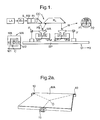
- Figure 1 schematically depicts a lithographic projection apparatus 1 according to the present invention.
- the apparatus comprises:
- the source LA (e . g . a laser-produced plasma source, a discharge source, or an undulator or wiggler provided around the path of an electron beam in a storage ring or synchrotron) produces a beam of EUV radiation.
- This beam is fed into an illumination system (illuminator) IL, either directly or after having traversed conditioning means, such as a beam expander, for example.
- the illuminator IL may comprise adjusting means for setting the outer and/or inner radial extent (commonly referred to as ⁇ -outer and ⁇ -inner, respectively) of the intensity distribution in the beam.
- it will generally comprise various other components, such as an integrator and a condenser. In this way, the beam PB impinging on the mask MA has a desired intensity distribution in its cross-section.
- the source LA may be within the housing of the lithographic projection apparatus, but that it may also be remote from the lithographic projection apparatus, the radiation beam which it produces being led into the apparatus ( e.g. with the aid of suitable directing mirrors).
- the current invention and claims encompass both of these scenarios.
- the beam PB subsequently intercepts the mask MA, which is held on a mask table MT. Having been selectively reflected by the mask MA, the beam PB passes through the lens PL, which focuses the beam PB onto a target portion C of the substrate W.
- the substrate table WT can be moved accurately, e . g . so as to position different target portions C in the path of the beam PB.
- the first positioning means can be used to accurately position the mask MA with respect to the path of the beam PB, e . g . after mechanical retrieval of the mask MA from a mask library or during a scan.
- movement of the object tables MT, WT will be realized with the aid of a long-stroke module (course positioning) and a short-stroke module (fine positioning), which are not explicitly depicted in Figure 1.
- the depicted apparatus can be used in two different modes:
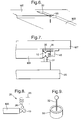
- Figure 2a shows mask MA for use in the lithographic apparatus of figure 1.
- the mask is provided with a mask gripping arrangement taking the form of three brackets 10 attached to the circumference of the mask to grip the mask at for holding and handling the mask.
- the brackets may be attached by any suitable means to the mask and are in the present embodiment attached using a vacuum-compatible glue such as an epoxy-based glue.
- brackets 10, or the gripping arrangement in general may also constitute an integral part of the mask.
- brackets on the mask has been chosen such as is convenient for handling the mask by mask manufacturers and mask users. They all will have their demands on the space around the mask that is available to arrange the brackets for their purposes. Further, the brackets are shown to be U-shaped in figures 2a and 3.
- the brackets are provided with grooves 11a, 11b in the top-side and bottom-side surfaces, respectively, that are substantially in line with the pattern-bearing and backside surfaces of the mask, but may also be provided above or below those surfaces.
- the grooves are directed to an imaginary point O that substantially coincides with a center point on a respective surface of the mask mask. In alternative embodiments such an imaginary point may be located within, below or above the mask, the grooves making an angle with the surfaces of the mask in such a configuration.
- Figure 3 also shows part of a mask gripper 20 for gripping mask MA in a mask handling part of the lithographic apparatus shown in figure 1.
- Device 20 comprises three pins 21b that are positioned on the gripper such that they can cooperate with three associated grooves provided in the three brackets of the above mask. It is seen that each pin 21b is provided with a ball 22b at its top. When the mask is held by gravity on the ball pins of the gripping device, the pins will be partially inserted into grooves 11b. Since the grooves are directed to a common point O, this results in a simple, but very effective and accurate kinematic positioning of the mask with respect to the gripping device.
- such a device 20 present in the handling system for masks or in a box for containing a mask can be made very simple, saving costs and improving reliability.
- such a configuration of grooves and (ball) pins for gripping the mask provides a minimum of microslip, which is a cause of particle generation by mechanical contact.
- the rounded surface presented by the ball provided on the pin proves to be advantageous in this respect.
- the mask When handling the mask with the above gripping device, the mask remains fixed on the gripping device by partial insertion of the pins in associated grooves provided in the brackets due to gravity. The mask may then be handled using some acceleration forces. The fixation of the mask on the gripping device under acceleration and deceleration forces will be increased by providing grooves that are directed to a common imaginary point located below or above the mask, as discussed above.
- FIG. 4 Some safety arrangement as schematically shown in figure 4 may be provided.
- the arrangement consisting of three upwards projecting pins 23 partially encloses a bracket of the mask when positioned on the gripping device, but does not make contact with the bracket, leaving a space between the bracket and the safety arrangement. Such a configuration will prevent the mask from falling off of the gripping device in emergency situations.
- pins 21a may be provided above the brackets for insertion in associated grooves in top-side surfaces of the brackets. This is shown in phantom figure 3. Pins 21a, 21b should still be lowered and lifted, respectively, as shown in figure 3 to grip the mask.
- Grooves may also be provided as an integral part of a rectangular shaped mask, i.e. not be provided in brackets.
- Figures 2b and 2c show details of edge regions of a rectangular mask, in which the grooves 11a, 11b are incorporated in the edge region.
- Figure 2d shows a detail of a mask MA having brackets 10 comprising two grooves 33b, 34b in its top surface and two grooves 33a, 34a in its bottom surface.
- Three brackets 10 are provided around the mask as is shown in figure 2a.
- Four sets of grooves are therefore provided, two sets at one side of the mask and two sets at the other side.
- the mask may be held by a set of pins (protrusions) of one gripper cooperating with one set of grooves of the mask.
- the other sets of grooves allow the mask to be transferred to another gripper.
- FIGS. 5a, 5b and 5c show details of a lower part of a bracket 10 with grooves 33a, 34a for cooperation with a protrusion or pin 31 of one gripper (not shown) and a protrusion 32 of another gripper (also not shown), respectively.
- Each gripper comprises a set of three protrusions 31 or 32.
- FIG 5a it is shown that the mask is held by the first gripper through insertion of protrusion 31 of the first gripper in groove 33a. Subsequently, the second gripper is raised so as to insert its protrusion 32 into groove 34a of bracket 10 attached to the mask, as is shown in figure 5b.
- FIG. 5c shows that the mask is held only by the second gripper of which protrusion 32 is inserted in groove 34a.
- Protrusions 31, 32 are shown as thin poles having a ball on top so as to have some resilience in a plane parallel to the mask (and perpendicular to protrusions 31, 32), as depicted by the double arrows in figure 5b for protrusion 31.
- the resilience allows easy adaption of the protrusions to a kinematically-determined position determined by cooperation of the pins and grooves, and assures an even more gentle take-over.
- the lithographic apparatus is only schematically shown.
- the mask table may be mounted such that the mask pattern will be facing downward.
- the mask MA may then be held by electrostatic forces at its back for holding it against gravity and acceleration and deceleration forces of mask table MT.
- a mask gripper as discussed above is used to transport the mask to the mask table.
- a take-over should take place to transfer the mask to the mask table.
- a relative movement of mask table and gripper will generally occur. If the mask were to be taken directly to the mask-bearing surface of the mask table on which it is to be held by an electrostatic force, slip between the mask-bearing surface and the backside of the mask will occur. This will cause particle generation and the generated particle will become trapped in between mask and mask-bearing surface to cause mask deformation on a scale that is not tolerable in an EUV lithographic apparatus.
- pins 35 are provided on respective leaf springs 36 that are mounted to the mask table, as shown in figure 6, so as to allow movement in a vertical Z direction (as depicted by the double arrow in figure 6), but not to allow movement in a horizontal XY plane.
- pins 21b, 31, 32 that are mounted to the gripper are constructed such as to be resilient in the XY plane but rigid in the Z direction, as is shown for pins (protrusions) 31, 32 depicted in figures 5a, 5b and 5c.
- the degrees of freedom of pins 35 on the mask table are therefore complementary to the degrees of freedom of pins 21b, 31, 32 of the gripper.
- Pins 35 in figure 6 are schematically depicted to have a rounded top. Other constructions of pins 31, 32, 35 to allow for the respective degrees of freedom may also be envisaged.
- the mask is brought towards the mask table by the gripper having pins 21b, 31 or 32. Subsequently, the gripper with the mask will be raised (or the mask table lowered) for the pins 35 of the mask table to make contact with their respective grooves 11a provided on the mask. The mask is then restricted to move perpendicular to mask table MT, but not parallel to it. Take-over will be completed by electrostatic attraction of mask MA against the mask-bearing surface MB of mask table MT.
- pins and respective grooves are preferably of a material that is very resistant to wear, i.e. (very) hard and non-brittle materials that are (substantially) not reactive.
- the pins and grooves can be made of or in such materials or may be coated with such materials. Examples of such materials and coatings are diamond-like coatings (DLC coatings), silicon nitride, titanium nitride, etceteras.
- Safety bracket 40 is mounted on the mask table.
- Safety bracket 40 is shaped for cooperation with an appropriately shaped bracket 10 mounted on mask MA, as is schematically depicted in figure 7.
- the gripper has been described such that the mask is held on the gripper by a gravity force.
- a gripper 25 coming from above, for instance, for take-over of the mask to another part of the apparatus or to lower the mask in a mask storage box.
- Such a gripper 25 will have downward oriented pins for cooperation with upwards oriented grooves.
- Electromagnetic holding means may be provided to hold mask MA against the pins.
- the gripper may be provided with means to electrostatically hold mask MA against gripper 25 as it is held against mask table MT.
- brackets 10 of a magnetic or magnetizable material (for instance, martensitic stainless steel) and to include an electric coil 55 in the complementary gripper, as is schematically depicted in figure 8.
- An electric current flowing through the coil will induce a magnetic field attracting the bracket of magnetic or magetizable material.
- Figure 8 also shows protrusions 26 of gripper 25 to be resilient in a plane parallel to mask MA for gentle take-over of the mask.
- the magnetic field of coil 55 will also act to attract any contaminant particles of magnetic or magnetizable material that may become released due to mechanical contact of gripper and mask.
- a permanent magnet or electromagnet may also be mounted near protrusions of grippers, which do not employ a magnetic field to hold the mask, so as to attract contaminant particles for further reducing the risk of contamination of the mask.
- Figure 9 shows a pin and a permanent magnet 56 of a gripper, which is not further shown, for attracting particles released during mechanical contact made.
- a magnet permanent magnet or electromagnet
- Such a provision of a magnet is not limited to the type of gripper disclosed here, but may be provided with any type of gripper to avoid contamination of the mask.
- Figure 10 depicts another embodiment of the invention for handling the mask.
- the mask is mounted in a frame 60 that is provided with recesses 11a, 11b for handling.
- the mask may be mounted by gravity in the frame or by some appropriate clamping means (not shown).
- Pads of a magnetic or magnetizable material may be provided at selected parts on the mask for contact with some type of gripper to mount the mask into the frame or to handle it otherwise. Particles released from the metal pad can be attracted by a magnetic field as described above to prevent particle contamination of the mask.
- the mask gripper disclosed as a part of the lithographic projection apparatus of figure 1 may also be a part of other tools, such as a multilayer deposition apparatus, a mask writing apparatus, a mask cleaning apparatus, or a mask inspection apparatus, or part of a reticle storage box.
- Figure 11 schematically depicts part of a reticle storage incorporating top and bottom grippers according to the invention.
- the bottom gripper is constituted by bottom plate 81 supporting three pins 82 having rounded tops for cooperation with a bottom V-groove in brackets 10 of mask MA.
- the top gripper is constituted by cover 83 of the box that supports three protrusions 84 having a spring and ball for cooperation with top V-grooves in brackets 10 of mask MA.
- a spring may also be provided in protrusion 82 to suppress acceleration forces.
- Bottom plate 81 and cover 83 may be made of polished aluminum, a low outgassing material. Inside the box an atmosphere of a protective (inert) gas is maintained.
Landscapes
- Physics & Mathematics (AREA)
- General Physics & Mathematics (AREA)
- Engineering & Computer Science (AREA)
- Library & Information Science (AREA)
- Exposure And Positioning Against Photoresist Photosensitive Materials (AREA)
- Registering Or Overturning Sheets (AREA)
Priority Applications (1)
| Application Number | Priority Date | Filing Date | Title |
|---|---|---|---|
| EP02251364A EP1237045B1 (fr) | 2001-03-01 | 2002-02-27 | Méthode pour transférer un masque lithographique |
Applications Claiming Priority (3)
| Application Number | Priority Date | Filing Date | Title |
|---|---|---|---|
| EP01301864 | 2001-03-01 | ||
| EP01301864 | 2001-03-01 | ||
| EP02251364A EP1237045B1 (fr) | 2001-03-01 | 2002-02-27 | Méthode pour transférer un masque lithographique |
Publications (3)
| Publication Number | Publication Date |
|---|---|
| EP1237045A2 true EP1237045A2 (fr) | 2002-09-04 |
| EP1237045A3 EP1237045A3 (fr) | 2002-10-02 |
| EP1237045B1 EP1237045B1 (fr) | 2007-05-02 |
Family
ID=26077098
Family Applications (1)
| Application Number | Title | Priority Date | Filing Date |
|---|---|---|---|
| EP02251364A Expired - Lifetime EP1237045B1 (fr) | 2001-03-01 | 2002-02-27 | Méthode pour transférer un masque lithographique |
Country Status (1)
| Country | Link |
|---|---|
| EP (1) | EP1237045B1 (fr) |
Cited By (3)
| Publication number | Priority date | Publication date | Assignee | Title |
|---|---|---|---|---|
| EP1500985A2 (fr) | 2003-07-22 | 2005-01-26 | ASML Netherlands B.V. | Dispositif de sécurité pour un appareil de formation de motifs lithographiques |
| WO2005119363A3 (fr) * | 2004-06-03 | 2006-02-02 | Nanobeam Ltd | Ensemble concu pour soutenir une piece ou un echantillon dans un systeme a faisceau de particules chargees |
| US7423733B2 (en) | 2003-07-22 | 2008-09-09 | Asml Netherlands B.V. | Lithographic apparatus, device manufacturing method, and device manufactured thereby with docking system for positioning a patterning device |
Family Cites Families (5)
| Publication number | Priority date | Publication date | Assignee | Title |
|---|---|---|---|---|
| US4610020A (en) * | 1984-01-06 | 1986-09-02 | The Perkin-Elmer Corporation | X-ray mask ring and apparatus for making same |
| JP3243168B2 (ja) * | 1996-02-06 | 2002-01-07 | キヤノン株式会社 | 原版保持装置およびこれを用いた露光装置 |
| JP3322167B2 (ja) * | 1997-05-29 | 2002-09-09 | ウシオ電機株式会社 | マスク保持フレームの支持構造 |
| AU2549899A (en) * | 1998-03-02 | 1999-09-20 | Nikon Corporation | Method and apparatus for exposure, method of manufacture of exposure tool, device, and method of manufacture of device |
| KR20010102421A (ko) * | 1999-02-26 | 2001-11-15 | 시마무라 테루오 | 노광장치, 리소그래피 시스템 및 반송방법 그리고디바이스 제조방법 및 디바이스 |
-
2002
- 2002-02-27 EP EP02251364A patent/EP1237045B1/fr not_active Expired - Lifetime
Cited By (4)
| Publication number | Priority date | Publication date | Assignee | Title |
|---|---|---|---|---|
| EP1500985A2 (fr) | 2003-07-22 | 2005-01-26 | ASML Netherlands B.V. | Dispositif de sécurité pour un appareil de formation de motifs lithographiques |
| US7423733B2 (en) | 2003-07-22 | 2008-09-09 | Asml Netherlands B.V. | Lithographic apparatus, device manufacturing method, and device manufactured thereby with docking system for positioning a patterning device |
| EP1500985A3 (fr) * | 2003-07-22 | 2009-05-06 | ASML Netherlands B.V. | Dispositif de sécurité pour un appareil de formation de motifs lithographiques |
| WO2005119363A3 (fr) * | 2004-06-03 | 2006-02-02 | Nanobeam Ltd | Ensemble concu pour soutenir une piece ou un echantillon dans un systeme a faisceau de particules chargees |
Also Published As
| Publication number | Publication date |
|---|---|
| EP1237045A3 (fr) | 2002-10-02 |
| EP1237045B1 (fr) | 2007-05-02 |
Similar Documents
| Publication | Publication Date | Title |
|---|---|---|
| US7153612B2 (en) | Mask handling method, and mask and device or apparatus comprising a gripper therefor, device manufacturing method and device manufactured thereby | |
| JP4854530B2 (ja) | リソグラフィ投影装置、およびデバイス製造方法 | |
| JP4910701B2 (ja) | 基板搬送装置、基板搬送方法および露光装置 | |
| EP1107066B1 (fr) | Appareil lithographique avec un dispositif de serrage de masque | |
| US6597429B2 (en) | Lithographic apparatus, device manufacturing method, and device manufactured thereby | |
| US6583858B2 (en) | Substrate holder for lithographic apparatus | |
| US7397539B2 (en) | Transfer apparatus for transferring an object, lithographic apparatus employing such a transfer apparatus, and method of use thereof | |
| US7791708B2 (en) | Lithographic apparatus, substrate table, and method for enhancing substrate release properties | |
| US20040180270A1 (en) | Container for a mask, method of transferring lithographic masks therein and method of scanning a mask in a container | |
| JP2004134755A (ja) | 基板ホルダおよびデバイス製造方法 | |
| US6956222B2 (en) | Lithographic apparatus and method of manufacturing a device | |
| US7466397B2 (en) | Safety mechanism for a lithographic patterning device | |
| EP1431825A1 (fr) | Appareil lithographique, méthode de fabrication d'un dispositif et porte-substrat | |
| EP1237045B1 (fr) | Méthode pour transférer un masque lithographique | |
| EP1148389A2 (fr) | Appareil lithographique, méthode de fabrication d'un dispositif, et dispositif fabriqué par cette méthode | |
| EP1256844A1 (fr) | Appareil lithographique | |
| EP1139176B1 (fr) | Appareil lithographique et support de masque | |
| EP1434094A1 (fr) | Récipient pour masque | |
| EP1341045A1 (fr) | Méthode de transfert d'un masque ou d'un substrat | |
| JP2010087156A (ja) | ステージ装置及び露光装置 | |
| EP1465011A1 (fr) | Dispositif de transfert d'un objet, méthode pour son utilisation et appareil de projection lithographique comprenant ledit dispositif de transfert | |
| EP1052546A2 (fr) | Manipulateur de substrats pour utilisation dans appareils de projection lithographique | |
| US7576831B2 (en) | Method and apparatus for maintaining a machine part | |
| EP1394611A1 (fr) | Appareil lithographique, méthode de fabrication d'un dispositif et dispositif fabriqué par cette méthode | |
| US20050134830A1 (en) | Safety mechanism for a lithographic patterning device |
Legal Events
| Date | Code | Title | Description |
|---|---|---|---|
| PUAI | Public reference made under article 153(3) epc to a published international application that has entered the european phase |
Free format text: ORIGINAL CODE: 0009012 |
|
| PUAL | Search report despatched |
Free format text: ORIGINAL CODE: 0009013 |
|
| AK | Designated contracting states |
Kind code of ref document: A2 Designated state(s): AT BE CH CY DE DK ES FI FR GB GR IE IT LI LU MC NL PT SE TR |
|
| AX | Request for extension of the european patent |
Free format text: AL;LT;LV;MK;RO;SI |
|
| AK | Designated contracting states |
Kind code of ref document: A3 Designated state(s): AT BE CH CY DE DK ES FI FR GB GR IE IT LI LU MC NL PT SE TR |
|
| AX | Request for extension of the european patent |
Free format text: AL;LT;LV;MK;RO;SI |
|
| AKX | Designation fees paid | ||
| 17P | Request for examination filed |
Effective date: 20030331 |
|
| RBV | Designated contracting states (corrected) |
Designated state(s): DE FR GB IT NL |
|
| REG | Reference to a national code |
Ref country code: DE Ref legal event code: 8566 |
|
| 17Q | First examination report despatched |
Effective date: 20030723 |
|
| RAP1 | Party data changed (applicant data changed or rights of an application transferred) |
Owner name: ASML NETHERLANDS B.V. |
|
| RTI1 | Title (correction) |
Free format text: METHOD OF TAKING OVER A LITHOGRAPHIC MASK |
|
| GRAP | Despatch of communication of intention to grant a patent |
Free format text: ORIGINAL CODE: EPIDOSNIGR1 |
|
| GRAS | Grant fee paid |
Free format text: ORIGINAL CODE: EPIDOSNIGR3 |
|
| GRAA | (expected) grant |
Free format text: ORIGINAL CODE: 0009210 |
|
| AK | Designated contracting states |
Kind code of ref document: B1 Designated state(s): DE FR GB IT NL |
|
| REG | Reference to a national code |
Ref country code: GB Ref legal event code: FG4D |
|
| REF | Corresponds to: |
Ref document number: 60219844 Country of ref document: DE Date of ref document: 20070614 Kind code of ref document: P |
|
| ET | Fr: translation filed | ||
| PLBE | No opposition filed within time limit |
Free format text: ORIGINAL CODE: 0009261 |
|
| STAA | Information on the status of an ep patent application or granted ep patent |
Free format text: STATUS: NO OPPOSITION FILED WITHIN TIME LIMIT |
|
| 26N | No opposition filed |
Effective date: 20080205 |
|
| PGFP | Annual fee paid to national office [announced via postgrant information from national office to epo] |
Ref country code: NL Payment date: 20080214 Year of fee payment: 7 Ref country code: IT Payment date: 20080223 Year of fee payment: 7 Ref country code: GB Payment date: 20080220 Year of fee payment: 7 Ref country code: DE Payment date: 20080219 Year of fee payment: 7 |
|
| PGFP | Annual fee paid to national office [announced via postgrant information from national office to epo] |
Ref country code: FR Payment date: 20080214 Year of fee payment: 7 |
|
| GBPC | Gb: european patent ceased through non-payment of renewal fee |
Effective date: 20090227 |
|
| NLV4 | Nl: lapsed or anulled due to non-payment of the annual fee |
Effective date: 20090901 |
|
| REG | Reference to a national code |
Ref country code: FR Ref legal event code: ST Effective date: 20091030 |
|
| PG25 | Lapsed in a contracting state [announced via postgrant information from national office to epo] |
Ref country code: NL Free format text: LAPSE BECAUSE OF NON-PAYMENT OF DUE FEES Effective date: 20090901 |
|
| PG25 | Lapsed in a contracting state [announced via postgrant information from national office to epo] |
Ref country code: DE Free format text: LAPSE BECAUSE OF NON-PAYMENT OF DUE FEES Effective date: 20090901 |
|
| PG25 | Lapsed in a contracting state [announced via postgrant information from national office to epo] |
Ref country code: GB Free format text: LAPSE BECAUSE OF NON-PAYMENT OF DUE FEES Effective date: 20090227 Ref country code: FR Free format text: LAPSE BECAUSE OF NON-PAYMENT OF DUE FEES Effective date: 20090302 |
|
| PG25 | Lapsed in a contracting state [announced via postgrant information from national office to epo] |
Ref country code: IT Free format text: LAPSE BECAUSE OF NON-PAYMENT OF DUE FEES Effective date: 20090227 |