EP1237172A2 - Selective tripping system - Google Patents
Selective tripping system Download PDFInfo
- Publication number
- EP1237172A2 EP1237172A2 EP02003396A EP02003396A EP1237172A2 EP 1237172 A2 EP1237172 A2 EP 1237172A2 EP 02003396 A EP02003396 A EP 02003396A EP 02003396 A EP02003396 A EP 02003396A EP 1237172 A2 EP1237172 A2 EP 1237172A2
- Authority
- EP
- European Patent Office
- Prior art keywords
- contact
- circuit
- magnet armature
- short
- arrangement according
- Prior art date
- Legal status (The legal status is an assumption and is not a legal conclusion. Google has not performed a legal analysis and makes no representation as to the accuracy of the status listed.)
- Granted
Links
Images

Classifications
-
- H—ELECTRICITY
- H01—ELECTRIC ELEMENTS
- H01H—ELECTRIC SWITCHES; RELAYS; SELECTORS; EMERGENCY PROTECTIVE DEVICES
- H01H71/00—Details of the protective switches or relays covered by groups H01H73/00 - H01H83/00
- H01H71/10—Operating or release mechanisms
- H01H71/1081—Modifications for selective or back-up protection; Correlation between feeder and branch circuit breaker
-
- H—ELECTRICITY
- H01—ELECTRIC ELEMENTS
- H01H—ELECTRIC SWITCHES; RELAYS; SELECTORS; EMERGENCY PROTECTIVE DEVICES
- H01H71/00—Details of the protective switches or relays covered by groups H01H73/00 - H01H83/00
- H01H71/10—Operating or release mechanisms
- H01H71/12—Automatic release mechanisms with or without manual release
- H01H71/46—Automatic release mechanisms with or without manual release having means for operating auxiliary contacts additional to the main contacts
Definitions
- the invention relates to an arrangement for selective triggering from one another horizontal, selectively staggered circuit breakers, especially circuit breakers and circuit breakers.
- the duration of action of the restraint system is determined by a timer.
- the Document EP 0 406 130 B1 shows an electromagnetic restraining system.
- Known arrangements for generating the blocking signal e.g. according to document DE 195 45 928 A1, requires means for status detection and for current detection of the circuit breaker directly affected by the short circuit, which in general as a complex electronic trigger and space-taking air coils around the main current paths are realized. Such Arrangements are therefore not for small and inexpensive circuit breakers suitable.
- EP 0 455 564 B1 discloses an overpressure release for a circuit breaker that detects an overpressure in the contact space appeals to the electric arcing in the electrodynamic Contact opening due to a short-circuit current flowing across the switch contacts arises.
- the circuit breaker further includes an operating mechanism with a latching device that has a release shaft by a thermally delayed overload release or an electromagnetic Short-circuit release can be released, which means that the trigger Operating mechanism of the circuit breaker transferred to the off state becomes.
- the overpressure release is activated to ensure selective triggering the trigger shaft with regard to the effect on the actuating mechanism with a time delay.
- this solution is not for selective tripping at small short-circuit currents where no noticeable arcing due to an electrodynamic contact opening occurs, suitable.
- That per main circuit of the circuit breaker from the magnet armature of an electromagnetic Short-circuit release actuated contact element provides a simple arrangement without selective electronic means Trip represents the output signal in the event of a short circuit as Blocking signal is passed to the upstream circuit breaker.
- the Signaling occurs through the interaction with the quick-release short-circuit release very fast and is independent of a contact opening or arcing in the associated contact space.
- Training The contact element as a normally open contact has the advantages that the arrangement does not require electrical energy in the non-triggering state and so that the susceptibility to interference is kept to a minimum.
- the invention Solution can be found in any circuit breaker with one or more Integrate short-circuit releases. A separate adjustment of the arrangement is not necessary as each short-circuit release itself via the setting element adjustable and the function of the arrangement is coupled to it. With the inventive arrangement equipped for selective triggering Circuit breakers can be easily converted into modules with several main current paths combine.
- An advantageous development of the arrangement according to the invention consists in the equipment of the contact element with a spring contact, in particular with a commercially available microswitch or with a preloaded spring contact, between two fixed contacts attached to the setting element acts.
- the contact element can also have a sliding contact be equipped.
- FIG. 1 is a three-pole circuit breaker for each of the three main current paths an electromagnetic short-circuit release 4 is provided.
- the of a tension spring 5 loaded magnet armature 6 is in the rest position - i.e. when no short-circuit current flows through the main current path - one for all Main current paths responsible, adjustable adjustment element 7 for adjustment of the tripping current.
- a magnetic yoke 8 is in the associated one Main current path arranged current winding 2 surrounded.
- the magnetic anchor 6 is in the event of a short circuit against the force of the tension spring 5 of attracted by the short-circuit current magnet yoke 8.
- the dressed Magnetic armature 6 acts upon a person responsible for all main current paths mechanical transmission element 10.
- the magnet armature 6 is as in Magnetic yoke 8 mounted hinged anchor executed. Between each magnet armature 6 and the adjusting element 7 is connected to signal connections 11, 12 Contact element 14 formed by the attracting magnet armature 6 can be transferred from the open to the closed state.
- the signal connections 11, 12 lead over conductor tracks provided in the adjusting element 7 15, 16 to all three contact elements 14, which are thus connected in parallel are.
- there is a blocking signal at the signal connections 11, 12 inferred that for the purpose of selective triggering on the actuating mechanism or the trigger system of an upstream circuit breaker to be led.
- FIGS. 2 and 3 show an embodiment of a contact element 14a a spring contact 18a.
- the preloaded spring contact 18a is behind one formed on the adjusting element 7 molded snap hook 20.
- flat Fixed contacts 22a or 23a i.e., the closed contact element 14a generates a blocking signal.
- the magnet armature 8 is in the in Fig. 2 shown rest position, then the spring contact 18a under the action the tension spring 5 is lifted from the fixed contact 23a, i.e. the closed one Contact element 14a does not output a blocking signal.
- Fig. 4 shows another embodiment of a contact element 14b with a pin-shaped configuration of the fixed contacts 22b and 23b and with a biased torsion spring designed spring contact 18b, with its spiral End 25b at which a fixed contact 23b is fixed.
- I'm unaffected Condition i.e. in the event of a short circuit, the hook-shaped other stands End 24b of the preloaded spring contact 18b with the other fixed contact 22b in conductive connection.
- the present invention is not limited to the above-described embodiments limited, but also includes all within the meaning of the invention equivalent embodiments.
- the invention can be to the effect that the contact elements as commercially available Microswitches are designed or equipped with a sliding contact.
Landscapes
- Breakers (AREA)
Abstract
Die Erfindung betrifft eine Anordnung zur selektiven Auslösung von hintereinander
geschalteten, selektiv gestaffelten Schutzschaltern mit einem eine Verklinkungseinrichtung
enthaltenden Betätigungsmechanismus, wobei ein vom
Kurzschluss direkt betroffener Schutzschalter ein Blockiersignal an den Betätigungsmechanismus
bzw. das Auslösesystem des vorgeschalteten Schutzschalters
ausgibt. Das zu lösende Problem besteht in einer von Vorgängen im
Kontaktraum des Schutzschalters unabhängigen und unaufwendigen Erzeugung
eines Blockiersignals. Dazu ist für jede Hauptstrombahn ein elektromagnetischer
Kurzschlussauslöser (4) vorgesehen, dessen Magnetanker (6) mit
einem Kontaktelement (14a) in Wirkverbindung steht, das an dem Einstellelement
(7) für den Kurzschlussauslöser (4) angeordnet ist.
Description
Die Erfindung betrifft eine Anordnung zur selektiven Auslösung von hintereinander liegenden, selektiv gestaffelten Schutzschaltern, insbesondere von Leitungsschutzschalter und Leistungsschalter.The invention relates to an arrangement for selective triggering from one another horizontal, selectively staggered circuit breakers, especially circuit breakers and circuit breakers.
Aus der Druckschrift DE 30 20 111 A1 ist eine Anordnung von in Reihe liegenden, selektiv gestaffelten strombegrenzenden Leistungsschaltern mit je einem Schnellstauslösesystem bekannt, das im Kurzschlussfall unabhängig vom Betätigungsmechanismus schnell und damit strombegrenzend das Kontaktsystem öffnet. Die vom Kurzschluss direkt betroffenen Leistungsschalter geben ein Blockiersignal an den Betätigungsmechanismus des jeweils in Einspeiserichtung vorgeschalteten Leistungsschalters. Die Leistungsschalter besitzen ein Fesselungssystem, das die beweglichen Kontakte nach einem bestimmten Öffnungsweg kurzzeitig in der Offenstellung festhält und wieder freigibt, wenn der Betätigungsmechanismus ein Blockiersignal von einem nachgeordneten Leistungsschalter erhalten hat. Wenn das Blockiersignal ausbleibt, löst der Betätigungsmechanismus aus und überführt das Kontaktsystem in die endgültige Ausschaltstellung, wodurch gleichzeitig die Fesselung aufgehoben wird. Die Wirkdauer des Fesselungssystems wird durch ein Zeitglied bestimmt. Die Druckschrift EP 0 406 130 B1 zeigt ein elektromagnetisch wirkendes Fesselungssystem. Bekannte Anordnungen zur Erzeugung des Blockiersignals, z.B. nach Druckschrift DE 195 45 928 A1, erfordert Mittel zur Zustandserkennung und zur Stromerfassung des vom Kurzschluss direkt betroffenen Leistungsschalters, die im allgemeinen als aufwendiger elektronischer Auslöser und raumeinnehmende Luftspulen um die Hauptstrombahnen realisiert sind. Derartige Anordnungen sind daher nicht für kleine und preiswerte Schutzschalter geeignet. Die Druckschrift EP 0 455 564 B1 offenbart einen Überdruckauslöser für einen Leistungsschalter, der auf einen im Kontaktraum auftretenden Überdruck anspricht, der durch die Lichtbogenbildung bei der elektrodynamischen Kontaktöffnung infolge eines über die Schaltkontakte fließenden Kurzschlussstromes entsteht. Der Leistungsschalter umfasst weiterhin einen Betätigungsmechanismus mit einer Verklinkungseinrichtung, die über eine Auslösewelle durch einen thermisch verzögerten Überlastauslöser oder einen elektromagnetischen Kurzschlussauslöser entklinkbar ist, wodurch über den auslösenden Betätigungsmechanismus der Leistungsschalter in den Aus-Zustand überführt wird. Um eine selektive Auslösung zu gewährleisten, beaufschlagt der Überdruckauslöser die Auslösewelle hinsichtlich der Wirkung auf den Betätigungsmechanismus mit einer zeitlichen Verzögerung. Diese Lösung ist allerdings nicht zum selektiven Auslösen bei kleinen Kurzschlussströmen, bei denen keine merkliche Lichtbogenbildung infolge einer elektrodynamischen Kontaktöffnung auftritt, geeignet.From the document DE 30 20 111 A1 an arrangement of in-line, selectively staggered current-limiting circuit breakers with one each Rapid release system known that in the event of a short circuit regardless of the actuation mechanism the contact system is fast and therefore current-limiting opens. Give the circuit breakers directly affected by the short circuit a blocking signal to the actuating mechanism of each in the feed direction upstream circuit breaker. The circuit breakers own a captive system that moves the movable contacts according to a certain Holds the opening path briefly in the open position and releases it again when the actuating mechanism receives a blocking signal from a downstream one Circuit breaker has received. If the blocking signal fails, the Actuating mechanism and converts the contact system into the final one Switch-off position, whereby the bondage is released at the same time. The duration of action of the restraint system is determined by a timer. The Document EP 0 406 130 B1 shows an electromagnetic restraining system. Known arrangements for generating the blocking signal, e.g. according to document DE 195 45 928 A1, requires means for status detection and for current detection of the circuit breaker directly affected by the short circuit, which in general as a complex electronic trigger and space-taking air coils around the main current paths are realized. such Arrangements are therefore not for small and inexpensive circuit breakers suitable. EP 0 455 564 B1 discloses an overpressure release for a circuit breaker that detects an overpressure in the contact space appeals to the electric arcing in the electrodynamic Contact opening due to a short-circuit current flowing across the switch contacts arises. The circuit breaker further includes an operating mechanism with a latching device that has a release shaft by a thermally delayed overload release or an electromagnetic Short-circuit release can be released, which means that the trigger Operating mechanism of the circuit breaker transferred to the off state becomes. The overpressure release is activated to ensure selective triggering the trigger shaft with regard to the effect on the actuating mechanism with a time delay. However, this solution is not for selective tripping at small short-circuit currents where no noticeable arcing due to an electrodynamic contact opening occurs, suitable.
Daraus ergibt sich als Aufgabe, die selektive Auslösung mit vertretbarem Aufwand und unabhängig von Vorgängen im Kontaktraum durchzuführen.This results in the task of selective triggering with reasonable effort and to be carried out independently of processes in the contact room.
Ausgehend von einer Anordnung der eingangs genannten Art wird die Aufgabe erfindungsgemäß durch die kennzeichnenden Merkmale des unabhängigen Anspruches gelöst, während den abhängigen Ansprüchen vorteilhafte Weiterbildungen der Erfindung zu entnehmen sind.Starting from an arrangement of the type mentioned at the outset, the task according to the invention by the characterizing features of the independent Claim solved, while the dependent claims advantageous Further developments of the invention can be found.
Das pro Hauptstrombahn des Schutzschalters vom Magnetanker eines elektromagnetischen Kurzschlussauslösers beaufschlagte Kontaktelement stellt eine einfache, ohne elektronische Mittel auskommende Anordnung zur selektiven Auslösung dar, deren Ausgangssignal im Falle eines Kurzschlusses als Blockiersignal an den vorgeschalteten Schutzschalter weitergegeben wird. Die Signalmeldung erfolgt durch die Interaktion mit dem schnellauslösenden Kurzschlussauslöser sehr schnell und ist unabhängig von einer Kontaktöffnung oder einer Lichtbogenbildung im zugehörigen Kontaktraum. Die Ausbildung des Kontaktelementes als Schließerkontakt hat die Vorteile, dass die Anordnung im nicht auslösendem Zustand keine elektrische Energie erfordert und damit die Störanfälligkeit auf ein Mindestmaß beschränkt ist. Die erfindungsgemäße Lösung lässt sich in jeden Schutzschalter mit einem oder mehreren Kurzschlussauslösern integrieren. Eine gesonderte Justierung der Anordnung ist nicht erforderlich, da jeder Kurzschlussauslöser selbst über das Einstellelement einstellbar und die Funktion der Anordnung daran gekoppelt ist. Mit der erfindungsgemäßen Anordnung zur selektiven Auslösung ausgestattete Schutzschalter lassen sich ohne weiteres zu Modulen mit mehreren Hauptstrombahnen kombinieren.That per main circuit of the circuit breaker from the magnet armature of an electromagnetic Short-circuit release actuated contact element provides a simple arrangement without selective electronic means Trip represents the output signal in the event of a short circuit as Blocking signal is passed to the upstream circuit breaker. The Signaling occurs through the interaction with the quick-release short-circuit release very fast and is independent of a contact opening or arcing in the associated contact space. Training The contact element as a normally open contact has the advantages that the arrangement does not require electrical energy in the non-triggering state and so that the susceptibility to interference is kept to a minimum. The invention Solution can be found in any circuit breaker with one or more Integrate short-circuit releases. A separate adjustment of the arrangement is not necessary as each short-circuit release itself via the setting element adjustable and the function of the arrangement is coupled to it. With the inventive arrangement equipped for selective triggering Circuit breakers can be easily converted into modules with several main current paths combine.
Eine vorteilhafte Weiterbildung der erfindungsgemäßen Anordnung besteht in der Ausstattung des Kontaktelementes mit einem Federkontakt, insbesondere mit einem handelsüblichen Mikroschalter oder mit einem vorgespannten Federkontakt, der zwischen zwei auf dem Einstellelement befestigten Festkontakten wirkt. Anderseits kann das Kontaktelement auch mit einem Schleifkontakt ausgestattet sein.An advantageous development of the arrangement according to the invention consists in the equipment of the contact element with a spring contact, in particular with a commercially available microswitch or with a preloaded spring contact, between two fixed contacts attached to the setting element acts. On the other hand, the contact element can also have a sliding contact be equipped.
Eine vorteilhafte Weiterbildung besteht weiterhin darin, dass zur Ausgabe eines gemeinsamen Blockiersignals die den einzelnen Hauptstrombahnen gehörenden Kontaktelemente kostengünstig parallel geschaltet sind.An advantageous further development consists in the fact that to issue a common blocking signal belonging to the individual main current paths Contact elements are inexpensively connected in parallel.
Weitere Einzelheiten und Vorteile der Erfindung ergeben sich aus dem folgenden, anhand von Figuren erläuterten Ausführungsbeispiel. Es zeigen
- Figur 1:
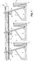
- eine erfindungsgemäße Anordnung in schematischer Darstellung;
- Figur 2:
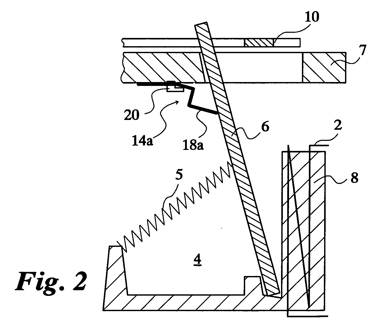
- eine Ausführungsform der Anordnung nach Fig. 1;
- Figur 3:
- eine Einzelheit der Ausführung nach Fig. 2;
- Figur 4:
- eine Einzelheit einer weiteren Ausführung.
- Figure 1:
- an arrangement according to the invention in a schematic representation;
- Figure 2:
- an embodiment of the arrangement of FIG. 1;
- Figure 3:
- a detail of the embodiment of FIG. 2;
- Figure 4:
- a detail of another execution.
Nach Fig. 1 ist für jede der drei Hauptstrombahnen eines dreipoligen Schutzschalters
ein elektromagnetischer Kurzschlussauslöser 4 vorgesehen. Der von
einer Zugfeder 5 beaufschlagte Magnetanker 6 liegt in Ruhelage - d.h., wenn
kein Kurzschlussstrom durch die Hauptstrombahn fließt - an einem für alle
Hauptstrombahnen zuständigen, verschiebbaren Einstellelement 7 zur Einstellung
des Auslösestromes an. Ein Magnetjoch 8 wird von einer in der zugehörigen
Hauptstrombahn angeordneten Stromwicklung 2 umgeben. Der Magnetanker
6 wird im Kurzschlussfall entgegen der Kraftwirkung der Zugfeder 5 von
dem vom Kurzschlussstrom umflossenen Magnetjoch 8 angezogen. Der angezogene
Magnetanker 6 beaufschlagt dabei ein für alle Hauptstrombahnen zuständiges,
mechanisches Übertragungselement 10. Das im Kurzschlussfall
gemäß Fig. 1 nach rechts verschobene Übertragungselement 10 beaufschlagt
seinerseits die Verklinkungseinrichtung eines Betätigungsmechanismus des
Schutzschalters, wodurch der Betätigungsmechanismus ausgelöst und damit
die Hauptstrombahnen unterbrochen werden. Der Magnetanker 6 ist als im
Magnetjoch 8 gelagerter Klappanker ausgeführt. Zwischen jedem Magnetanker
6 und dem Einstellelement 7 ist ein mit Signalanschlüssen 11, 12 verbundenes
Kontaktelement 14 ausgebildet, das durch den anziehenden Magnetanker
6 vom geöffneten in den geschlossenen Zustand überführbar ist. Die Signalanschlüsse
11, 12 führen über im Einstellelement 7 vorgesehene Leiterbahnen
15, 16 zu allen drei Kontaktelementen 14, die damit parallel geschaltet
sind. Im Kurzschlussfall ist an den Signalanschlüssen 11, 12 ein Blockiersignal
zu entnehmen, das zum Zwecke einer selektiven Auslösung an den Betätigungsmechanismus
bzw. das Auslösesystem eines vorgeschalteten Schutzschalters
geführt wird.1 is a three-pole circuit breaker for each of the three main current paths
an electromagnetic short-
Fig. 2 und Fig. 3 zeigen eine Ausgestaltung eines Kontaktelementes 14a mit
einem Federkontakt 18a. Der vorgespannte Federkontakt 18a ist hinter einem
am Einstellelement 7 angeformten Schnapphaken 20 festgelegt. Bei angezogenem
Magnetanker 6 überbrückt der Federkontakt 18a unter der Wirkung
seiner Vorspannung zwei mit den Leiterbahnen 15 und 16 integrierte, flache
Festkontakte 22a bzw. 23a, d.h., das geschlossene Kontaktelement 14a generiert
ein Blockiersignal . Befindet sich der Magnetankers 8 dagegen in der in
Fig. 2 gezeigten Ruhelage, dann wird der Federkontakt 18a unter der Einwirkung
der Zugfeder 5 von dem Festkontakt 23a abgehoben, d.h., das geschlossene
Kontaktelement 14a gibt kein Blockiersignal aus. 2 and 3 show an embodiment of a
Fig. 4 zeigt eine andere Ausführung eines Kontaktelementes 14b mit einer
stiftförmigen Ausgestaltung der Festkontakte 22b und 23b und mit einem als
vorgespannte Drehfeder ausgestalteten Federkontakt 18b, der mit seinem spiralförmigen
Ende 25b an dem einen Festkontakt 23b festgelegt ist. Im unbeaufschlagte
Zustand, d.h. im Kurzschlussfall, steht das hakenförmige andere
Ende 24b des vorgespannten Federkontaktes 18b mit dem anderen Festkontakt
22b in leitender Verbindung. Unter Nennstrom- oder Überlastbedingungen
wird dagegen das hakenförmige Ende 24b durch den Magnetanker von dem
Festkontakt 22b abgehoben.Fig. 4 shows another embodiment of a
Die vorliegende Erfindung ist nicht auf die vorstehend beschriebenen Ausführungsformen beschränkt, sondern umfasst auch alle im Sinne der Erfindung gleichwirkenden Ausführungsformen. So lässt sich die Erfindung beispielsweise dahingehend ausgestalten, dass die Kontaktelemente als handelsübliche Mikroschalter ausgeführt oder mit einem Schleifkontakt ausgestattet sind.The present invention is not limited to the above-described embodiments limited, but also includes all within the meaning of the invention equivalent embodiments. For example, the invention can be to the effect that the contact elements as commercially available Microswitches are designed or equipped with a sliding contact.
Claims (6)
Applications Claiming Priority (2)
| Application Number | Priority Date | Filing Date | Title |
|---|---|---|---|
| DE2001109950 DE10109950A1 (en) | 2001-03-01 | 2001-03-01 | Selective trip arrangement |
| DE10109950 | 2001-03-01 |
Publications (3)
| Publication Number | Publication Date |
|---|---|
| EP1237172A2 true EP1237172A2 (en) | 2002-09-04 |
| EP1237172A3 EP1237172A3 (en) | 2004-03-17 |
| EP1237172B1 EP1237172B1 (en) | 2005-09-14 |
Family
ID=7675982
Family Applications (1)
| Application Number | Title | Priority Date | Filing Date |
|---|---|---|---|
| EP20020003396 Expired - Lifetime EP1237172B1 (en) | 2001-03-01 | 2002-02-14 | Selective tripping arrangement |
Country Status (2)
| Country | Link |
|---|---|
| EP (1) | EP1237172B1 (en) |
| DE (2) | DE10109950A1 (en) |
Cited By (1)
| Publication number | Priority date | Publication date | Assignee | Title |
|---|---|---|---|---|
| EP2136383A3 (en) * | 2008-06-17 | 2013-06-26 | GEWISS S.p.A. | A control device for an automatic reset apparatus |
Family Cites Families (4)
| Publication number | Priority date | Publication date | Assignee | Title |
|---|---|---|---|---|
| DE1087680B (en) * | 1958-02-04 | 1960-08-25 | Elektroschaltgeraete Goerlitz | Electromagnetic overcurrent release |
| DD106745A1 (en) * | 1973-07-13 | 1974-06-20 | ||
| US5301083A (en) * | 1991-09-30 | 1994-04-05 | Eaton Corporation | Remote control residential circuit breaker |
| DE19930089A1 (en) * | 1999-06-30 | 2001-01-04 | Moeller Gmbh | Selective trip arrangement |
-
2001
- 2001-03-01 DE DE2001109950 patent/DE10109950A1/en not_active Withdrawn
-
2002
- 2002-02-14 EP EP20020003396 patent/EP1237172B1/en not_active Expired - Lifetime
- 2002-02-14 DE DE50204214T patent/DE50204214D1/en not_active Expired - Lifetime
Cited By (1)
| Publication number | Priority date | Publication date | Assignee | Title |
|---|---|---|---|---|
| EP2136383A3 (en) * | 2008-06-17 | 2013-06-26 | GEWISS S.p.A. | A control device for an automatic reset apparatus |
Also Published As
| Publication number | Publication date |
|---|---|
| DE10109950A1 (en) | 2002-09-05 |
| EP1237172B1 (en) | 2005-09-14 |
| EP1237172A3 (en) | 2004-03-17 |
| DE50204214D1 (en) | 2005-10-20 |
Similar Documents
| Publication | Publication Date | Title |
|---|---|---|
| DE69401971T2 (en) | Magnetothermal release unit | |
| DE2808602A1 (en) | SWITCHING DEVICE WITH ANTIPREL LOCKING | |
| EP1186084A1 (en) | Electrical circuit breaker for protecting against overcurrents | |
| CH653188A5 (en) | SELECTIVE SAFETY SWITCHING DEVICE FOR PROTECTING A POWER DISTRIBUTION SYSTEM. | |
| EP0954873A1 (en) | Load disconnecting switch, in particular for the load circuit of a motor vehicle battery | |
| WO2009114890A1 (en) | Trigger module for a switching device | |
| DE69931226T2 (en) | Tripping device for circuit breaker | |
| DE10244961B3 (en) | Selective line protection circuit breaker includes shunt current path generating at least part of the magnetic excitation for the magnetic release | |
| EP1266388A1 (en) | Selective tripping device for a circuit breaker | |
| EP2286432A1 (en) | Electric selective automatic switch | |
| EP1237172B1 (en) | Selective tripping arrangement | |
| EP1065690A2 (en) | Selective tripping device | |
| DE102010019353B3 (en) | Power switch e.g. single-pole power switch, has plate spring extending in close proximity to moving contact in plane of motion, where plate spring is formed such that component holds moving contact in separation position | |
| DE3316230A1 (en) | Line and/or apparatus protection circuit breaker against excess current and short circuit | |
| EP1237171B1 (en) | Selective tripping system | |
| EP0043020A1 (en) | Electric installation device, especially automatic switch | |
| DE3133200A1 (en) | Line protection circuit breaker, suitable for use as a preliminary automatic circuit breaker | |
| DE69119858T2 (en) | Power distribution device for the electrical energy of a distribution panel | |
| DE19741919C1 (en) | Switch-disconnecter e.g. for motor vehicle battery load circuit in emergency situations | |
| DE2720736C2 (en) | Maximum current limiter for an electrical switchgear | |
| EP0827251A2 (en) | Electrical low voltage switchgear | |
| EP0990247B1 (en) | Device for triggering an overload circuit breaker | |
| EP2680293A1 (en) | Release mechanism | |
| DE2625894C2 (en) | Electromagnetic overcurrent release for electrical switches | |
| EP0523420B1 (en) | Short-circuit instantaneous trip mechanism |
Legal Events
| Date | Code | Title | Description |
|---|---|---|---|
| PUAI | Public reference made under article 153(3) epc to a published international application that has entered the european phase |
Free format text: ORIGINAL CODE: 0009012 |
|
| AK | Designated contracting states |
Kind code of ref document: A2 Designated state(s): AT BE CH CY DE DK ES FI FR GB GR IE IT LI LU MC NL PT SE TR |
|
| AX | Request for extension of the european patent |
Free format text: AL;LT;LV;MK;RO;SI |
|
| PUAL | Search report despatched |
Free format text: ORIGINAL CODE: 0009013 |
|
| AK | Designated contracting states |
Kind code of ref document: A3 Designated state(s): AT BE CH CY DE DK ES FI FR GB GR IE IT LI LU MC NL PT SE TR |
|
| AX | Request for extension of the european patent |
Extension state: AL LT LV MK RO SI |
|
| 17P | Request for examination filed |
Effective date: 20040901 |
|
| AKX | Designation fees paid |
Designated state(s): DE FR IT |
|
| GRAP | Despatch of communication of intention to grant a patent |
Free format text: ORIGINAL CODE: EPIDOSNIGR1 |
|
| GRAS | Grant fee paid |
Free format text: ORIGINAL CODE: EPIDOSNIGR3 |
|
| RTI1 | Title (correction) |
Free format text: SELECTIVE TRIPPING ARRANGEMENT |
|
| GRAA | (expected) grant |
Free format text: ORIGINAL CODE: 0009210 |
|
| AK | Designated contracting states |
Kind code of ref document: B1 Designated state(s): DE FR IT |
|
| REF | Corresponds to: |
Ref document number: 50204214 Country of ref document: DE Date of ref document: 20051020 Kind code of ref document: P |
|
| ET | Fr: translation filed | ||
| PLBE | No opposition filed within time limit |
Free format text: ORIGINAL CODE: 0009261 |
|
| STAA | Information on the status of an ep patent application or granted ep patent |
Free format text: STATUS: NO OPPOSITION FILED WITHIN TIME LIMIT |
|
| 26N | No opposition filed |
Effective date: 20060615 |
|
| PGFP | Annual fee paid to national office [announced via postgrant information from national office to epo] |
Ref country code: IT Payment date: 20090223 Year of fee payment: 8 |
|
| PGFP | Annual fee paid to national office [announced via postgrant information from national office to epo] |
Ref country code: FR Payment date: 20090213 Year of fee payment: 8 |
|
| PGFP | Annual fee paid to national office [announced via postgrant information from national office to epo] |
Ref country code: DE Payment date: 20100219 Year of fee payment: 9 |
|
| REG | Reference to a national code |
Ref country code: FR Ref legal event code: ST Effective date: 20101029 |
|
| PG25 | Lapsed in a contracting state [announced via postgrant information from national office to epo] |
Ref country code: FR Free format text: LAPSE BECAUSE OF NON-PAYMENT OF DUE FEES Effective date: 20100301 |
|
| PG25 | Lapsed in a contracting state [announced via postgrant information from national office to epo] |
Ref country code: IT Free format text: LAPSE BECAUSE OF NON-PAYMENT OF DUE FEES Effective date: 20100214 |
|
| REG | Reference to a national code |
Ref country code: DE Ref legal event code: R119 Ref document number: 50204214 Country of ref document: DE Effective date: 20110901 |
|
| PG25 | Lapsed in a contracting state [announced via postgrant information from national office to epo] |
Ref country code: DE Free format text: LAPSE BECAUSE OF NON-PAYMENT OF DUE FEES Effective date: 20110901 |