EP1237309B1 - Faseroptisches Übertragungssystem - Google Patents
Faseroptisches Übertragungssystem Download PDFInfo
- Publication number
- EP1237309B1 EP1237309B1 EP02075004A EP02075004A EP1237309B1 EP 1237309 B1 EP1237309 B1 EP 1237309B1 EP 02075004 A EP02075004 A EP 02075004A EP 02075004 A EP02075004 A EP 02075004A EP 1237309 B1 EP1237309 B1 EP 1237309B1
- Authority
- EP
- European Patent Office
- Prior art keywords
- services
- module
- packets
- transmission
- service
- Prior art date
- Legal status (The legal status is an assumption and is not a legal conclusion. Google has not performed a legal analysis and makes no representation as to the accuracy of the status listed.)
- Expired - Lifetime
Links
- 238000004891 communication Methods 0.000 title claims abstract description 16
- 239000000835 fiber Substances 0.000 title description 17
- 230000005540 biological transmission Effects 0.000 claims abstract description 78
- 230000003287 optical effect Effects 0.000 claims abstract description 53
- 239000013307 optical fiber Substances 0.000 claims abstract description 23
- 238000012545 processing Methods 0.000 claims abstract description 15
- 230000002776 aggregation Effects 0.000 claims description 18
- 238000004220 aggregation Methods 0.000 claims description 18
- RGNPBRKPHBKNKX-UHFFFAOYSA-N hexaflumuron Chemical compound C1=C(Cl)C(OC(F)(F)C(F)F)=C(Cl)C=C1NC(=O)NC(=O)C1=C(F)C=CC=C1F RGNPBRKPHBKNKX-UHFFFAOYSA-N 0.000 claims description 15
- 238000011144 upstream manufacturing Methods 0.000 claims description 11
- 230000004931 aggregating effect Effects 0.000 claims description 5
- 238000013507 mapping Methods 0.000 claims description 3
- 238000012856 packing Methods 0.000 claims description 3
- 238000009432 framing Methods 0.000 claims description 2
- 238000000034 method Methods 0.000 description 11
- 238000010586 diagram Methods 0.000 description 8
- 238000005516 engineering process Methods 0.000 description 5
- 238000006243 chemical reaction Methods 0.000 description 4
- 239000004744 fabric Substances 0.000 description 4
- 238000005538 encapsulation Methods 0.000 description 3
- 239000004065 semiconductor Substances 0.000 description 3
- GIYXAJPCNFJEHY-UHFFFAOYSA-N N-methyl-3-phenyl-3-[4-(trifluoromethyl)phenoxy]-1-propanamine hydrochloride (1:1) Chemical compound Cl.C=1C=CC=CC=1C(CCNC)OC1=CC=C(C(F)(F)F)C=C1 GIYXAJPCNFJEHY-UHFFFAOYSA-N 0.000 description 2
- 238000010276 construction Methods 0.000 description 2
- 239000011159 matrix material Substances 0.000 description 2
- 230000008569 process Effects 0.000 description 2
- 230000001360 synchronised effect Effects 0.000 description 2
- 238000012546 transfer Methods 0.000 description 2
- RYGMFSIKBFXOCR-UHFFFAOYSA-N Copper Chemical compound [Cu] RYGMFSIKBFXOCR-UHFFFAOYSA-N 0.000 description 1
- 230000008901 benefit Effects 0.000 description 1
- 230000000903 blocking effect Effects 0.000 description 1
- 239000000969 carrier Substances 0.000 description 1
- 230000008859 change Effects 0.000 description 1
- 229910052802 copper Inorganic materials 0.000 description 1
- 239000010949 copper Substances 0.000 description 1
- 238000012937 correction Methods 0.000 description 1
- 230000000694 effects Effects 0.000 description 1
- 238000004377 microelectronic Methods 0.000 description 1
- 230000011218 segmentation Effects 0.000 description 1
- 238000000926 separation method Methods 0.000 description 1
Images
Classifications
-
- H—ELECTRICITY
- H04—ELECTRIC COMMUNICATION TECHNIQUE
- H04L—TRANSMISSION OF DIGITAL INFORMATION, e.g. TELEGRAPHIC COMMUNICATION
- H04L69/00—Network arrangements, protocols or services independent of the application payload and not provided for in the other groups of this subclass
- H04L69/16—Implementation or adaptation of Internet protocol [IP], of transmission control protocol [TCP] or of user datagram protocol [UDP]
- H04L69/168—Implementation or adaptation of Internet protocol [IP], of transmission control protocol [TCP] or of user datagram protocol [UDP] specially adapted for link layer protocols, e.g. asynchronous transfer mode [ATM], synchronous optical network [SONET] or point-to-point protocol [PPP]
-
- H—ELECTRICITY
- H04—ELECTRIC COMMUNICATION TECHNIQUE
- H04L—TRANSMISSION OF DIGITAL INFORMATION, e.g. TELEGRAPHIC COMMUNICATION
- H04L9/00—Cryptographic mechanisms or cryptographic arrangements for secret or secure communications; Network security protocols
- H04L9/40—Network security protocols
-
- H—ELECTRICITY
- H04—ELECTRIC COMMUNICATION TECHNIQUE
- H04Q—SELECTING
- H04Q11/00—Selecting arrangements for multiplex systems
- H04Q11/0001—Selecting arrangements for multiplex systems using optical switching
- H04Q11/0062—Network aspects
- H04Q11/0071—Provisions for the electrical-optical layer interface
-
- H—ELECTRICITY
- H04—ELECTRIC COMMUNICATION TECHNIQUE
- H04L—TRANSMISSION OF DIGITAL INFORMATION, e.g. TELEGRAPHIC COMMUNICATION
- H04L69/00—Network arrangements, protocols or services independent of the application payload and not provided for in the other groups of this subclass
- H04L69/18—Multiprotocol handlers, e.g. single devices capable of handling multiple protocols
-
- H—ELECTRICITY
- H04—ELECTRIC COMMUNICATION TECHNIQUE
- H04L—TRANSMISSION OF DIGITAL INFORMATION, e.g. TELEGRAPHIC COMMUNICATION
- H04L69/00—Network arrangements, protocols or services independent of the application payload and not provided for in the other groups of this subclass
- H04L69/30—Definitions, standards or architectural aspects of layered protocol stacks
- H04L69/32—Architecture of open systems interconnection [OSI] 7-layer type protocol stacks, e.g. the interfaces between the data link level and the physical level
- H04L69/322—Intralayer communication protocols among peer entities or protocol data unit [PDU] definitions
- H04L69/324—Intralayer communication protocols among peer entities or protocol data unit [PDU] definitions in the data link layer [OSI layer 2], e.g. HDLC
-
- H—ELECTRICITY
- H04—ELECTRIC COMMUNICATION TECHNIQUE
- H04L—TRANSMISSION OF DIGITAL INFORMATION, e.g. TELEGRAPHIC COMMUNICATION
- H04L69/00—Network arrangements, protocols or services independent of the application payload and not provided for in the other groups of this subclass
- H04L69/30—Definitions, standards or architectural aspects of layered protocol stacks
- H04L69/32—Architecture of open systems interconnection [OSI] 7-layer type protocol stacks, e.g. the interfaces between the data link level and the physical level
- H04L69/322—Intralayer communication protocols among peer entities or protocol data unit [PDU] definitions
- H04L69/326—Intralayer communication protocols among peer entities or protocol data unit [PDU] definitions in the transport layer [OSI layer 4]
-
- H—ELECTRICITY
- H04—ELECTRIC COMMUNICATION TECHNIQUE
- H04Q—SELECTING
- H04Q11/00—Selecting arrangements for multiplex systems
- H04Q11/0001—Selecting arrangements for multiplex systems using optical switching
- H04Q11/0062—Network aspects
- H04Q2011/0084—Quality of service aspects
Definitions
- the present invention relates to fiber optic communication systems in general and, in particular, to a system for propagation of data between source and destination points over an optical metro access communication system.
- Access communication systems have become more widespread in recent years. These systems permit the transfer of information from one location to another, according to a variety of protocols, over different networks, most commonly the IP (Internet Protocol) network, the TDM (Time Division Multiplexing) network, and the ATM (Asynchronous Transmission Mode) network.
- IP Internet Protocol
- TDM Time Division Multiplexing
- ATM Asynchronous Transmission Mode
- data according to these protocols is transmitted optically over optical fibers, such as by means of DWDM (Dense Wavelength Division Multiplexing) which permit the transmission of significantly greater bandwidth than over traditional copper wires.
- DWDM Dens Wavelength Division Multiplexing
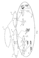
- Networks of varying sizes and data rates have been established for transmission of data throughout the world. These networks are illustrated schematically in Fig. 1.
- the smallest networks, at a local level, are known as local or enterprise networks.
- a plurality of local networks, which are located close to one another physically, typically are joined in a metro access network 14, which can cover a city, for example,
- a plurality of metro access networks 14 are joined together in a metro backbone network 16, covering a number of cities or a country, and, finally, a long haul backbone 18 couples several countries or metro backbones for long distance transmission.
- switches are used to put information onto these networks.
- these switches are required to change the data rate at which the data is transported. This, however, is not consistent throughout the world.
- different data rates are used in corresponding levels of networks in different locations.
- local access networks transmit over limited bandwidth, at data rates varying from T1,E1 (1.5-2 Megabits per second) to Gigabit Internet, and metro access networks between about OC-12 (622 Megabits per second) to OC-48 (2.5 Gigabits per second), while metro backbone and long haul backbone have data transmission at rates of 2.5 Gigabits per second and OC-48 times the number of wavelengths available and up to 10 Gigabits per second with DWDM optional network bandwidth expansion, so as to permit the transmission of increasing quantities of data.
- WDM Wavelength Division Multiplexing
- SDH Synchronous Optical Network
- DWDM Dense Wavelength Division Multiplexing
- DWDM is an optical technology used to increase bandwidth over existing fiber optic backbones.
- DWDM works by combining and transmitting multiple signals simultaneously at different wavelengths on the same fiber.
- one fiber is transformed into multiple virtual fibers,
- single fibers have been able to transmit data at speeds up to 400 Gigabits/sec and more. And, as vendors add more channels to each fiber, terabit capacity is on its way.
- the photonic access concentrator includes a traffic concentrator and a cell multiplexer. The concentrator receives the incoming traffic consisting of ATM cells and performs concentration and multiplexing. Data entering the system has been converted into ATM cells.
- Each network node is a high performance ATM packet switch, which accepts input cells at a selected rate and serves both as a LAN to LAN interconnect and as packet concentrator for traffic destined to other network nodes and LAN's.
- the present invention provides a data transmission system, which optimizes usage of the bandwith capacity of optical fibers, and reduces the investment in equipment required at each local site in the network. This is achieved by implementing a novel method of organizing data, to be transmitted in packets, which permits the transfer of data according to different protocols as is, without conversion from one protocol to another.
- the various services are collected at a local service collection unit, also called an Optical Network Terminal (ONT) in the specification, process into packets, and transmitted to an aggregator, which sorts the services from each service collection unit and joins together similar services from the various service collection units for transmission over the appropriate network.
- ONT Optical Network Terminal
- a system for data transmission over an optical network including at least one service collection unit including a collection module for collecting a plurality of services data to be transmitted, a processing module for processing the services in their original protocols into packets, and a packet transmission module for converting the services into optical signals on an optical fiber for transmission into a metro network; and an aggregator, coupled for optical communication to a plurality of service collection units, and including a soning module for sorting the services from a plurality of packets according to service type, and a service aggregation module for combining like services for transmission over an appropriate service network,
- the system service collection unit includes at least one services interface, a packetization module for receiving services from the interface and inserting the services into packets, a tagging module for tagging the packets, and a packet switch, coupled between the tagging module and a Trunk, for switching the packets to at least one service collection unit's optical transceiver.
- the system includes a service collection unit including at least one service interface, a packetization module for segmenting a bit stream and adding a tag indicating connection identification for each service, a packet switch for receiving a plurality of tagged segments and inserting them into transmission frames, for example of 2.5 Gigabits per second, preferably synchronous transmission frames such as Packet over SONET/SDH, and a service collection unit's optical transceiver for transmitting the transmission frames,
- the service collection unit further includes a transmission stream switch coupled between the packet switch and the service collection optical transceiver, for switching data between a plurality of optical fibers.
- the service collection unit's optical transceiver further includes a wavelength division multiplexer (WDM) for multiplexing the data onto a single optical fiber.
- WDM wavelength division multiplexer
- the system includes an aggregator unit coupled for upstream and downstream communication to the service collection unit, the aggregator unit including an aggregator's optical transceiver, a framing module for removing packets from a transmission frame, a packet switch for directing packets from a trunk according to destination, a sorting module for sorting services removed from packets, an aggregation module for aggregating like services and sending aggregated services to an appropriate network.
- the aggregator unit coupled for upstream and downstream communication to the service collection unit, the aggregator unit including an aggregator's optical transceiver, a framing module for removing packets from a transmission frame, a packet switch for directing packets from a trunk according to destination, a sorting module for sorting services removed from packets, an aggregation module for aggregating like services and sending aggregated services to an appropriate network.
- the present invention relates to a system and method for data transmission and receiving of data over an optical communication system, particularly at the local, metro access, and metro backbone (core) levels, which permits utilization of the full bandwidth of an optical communications fiber.
- the method includes encapsulation of service data, as is, in whatever protocol it is received, into a packet which looks and acts like a conventional Packet over SONET (PoS) or similar transmission frame, without requiring conversion of the data from one protocol to another, in a service collection unit.
- the packets are transmitted from a plurality of service collection units to an aggregator.
- the aggregator sorts the services from a number of packets coming from a plurality of service collection units and aggregates like services for transmittal over the appropriate network.
- the services thus, are transmitted over the corresponding network, as known today, but without requiring conversion to another protocol during the process.
- this method permits utilization of the full bandwidth of an optical fiber, by efficient use of a packet switch.
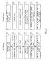
- FIG. 2 there is shown a functional block diagram of a service collection unit according to one embodiment of the invention.
- Services to be sent over a network are received through a service interface (block 20) as a bit stream.
- the bit stream is segmented and arranged into packets (block 22) for further processing, without regard to the content of the data being transmitted.
- All incoming traffic i.e., the incoming bit stream, received on a service port, is segmented into variable-length segments.
- the segments can be of pre-determined fixed length or the segments can have variable length within the particular service, for example, the length of an Ethernet packet.
- Each segment typically includes a destination address within the source network, a source address within the source network, information representing the length or type of the frame, and data to be transmitted in the frame. In most cases, a plurality of frames make up the entire data transmission.
- a header or tag is added to the segment (block 26).
- the tag includes information including the connection identification for the traffic, which is used herein to mean the connection between the traffic's source and destination end-points, for directing the traffic from its origin to its end point.
- connection identification for the traffic which is used herein to mean the connection between the traffic's source and destination end-points, for directing the traffic from its origin to its end point.
- the original segment is treated as a single block of data.
- MPLS Multi-Protocol Label Switching
- the Trunk encapsulates the tagged segment into a Point-to-Point Protocol (PPP) packet in a frame, preferably a High bit rate Digital Link Control (HDLC)-like frame.
- PPP Point-to-Point Protocol
- HDLC High bit rate Digital Link Control
- the packets are now inserted into a transmission frame, here illustrated as an OC-48c PoS (Packet over SONET/SDH) frame (block 28),
- OC-48c PoS Packet over SONET/SDH
- the HDLC-like frames are mapped onto a payload, and then transported to their destination, as if they were conventional PoS frames.
- the encapsulated segment can be scrambled, as known, before mapping onto transmission SONET frames.
- the transmission frames are now sent to a service collection unit's optical transceiver (block 30), preferably a 2.5Gb transceiver, for transmission over an optical fiber or fibers.
- an OC-48c stream switch can be provided between the framer and the transceiver to permit the operator to select to which transceiver the various frames will be sent.
- This transceiver can include a WDM laser with a specific wavelength. A plurality of such WDM transceivers can be combined over one fiber. In this case, the system will have the standard properties of a WDM transmission system.
- the service collection unit functions both upstream and downstream, performing the inverse functions.
- the operation of the unit in the downstream direction will be described in detail hereinbelow.
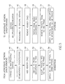
- the data is sent over the local or metro access network to an aggregator, whose operation is shown in block diagram form in Fig. 3. It will be appreciated that a number of lasers can be provided, each with its own wavelength, with a WDM multiplexer to unite them all onto a single optical fiber.
- the aggregator serves two upstream functions: sorting the services received in OC-48c frames from a variety of service collection units, and aggregating like services for transmission on the corresponding service network.
- the aggregator receives the incoming signals from the service collection units in an aggregator's optical transceiver.
- the optical signal is switched, as by means of a stream switch, to an appropriate transmission framer (block 32), here illustrated as an OC-48c framer.
- the aggregator first de-multiplexes the optical signals before sending the signals to the aggregator's optical transceiver.
- the PPP packets are removed from the transmission frames (block 34).
- the tags on the various packets are read, and the packets are switched from the trunk to another Trunk or to an Aggregator, according to the connection identification indicated in the packet's tag (block 36).
- the header or tag is removed from the packet (block 38), resulting in a plurality of segments of the various services traffic.
- Each service is reassembled to its original bit stream (block 40), and the aggregator combines like services together for transmission over the appropriate network, i.e., ATM, IP, TDM, WDM (block 42).
- the aggregator can combine the services by mere aggregation, loading services of the same kind (and in the same protocol) together onto the network. Alternatively, the aggregator can combine the services by multiplexing several services onto a single fiber over different wavelengths.
- the aggregator also functions both upstream and downstream, performing the inverse functions.
- the operation of the system of the present invention in the downstream direction is as follows, with further reference to Figs. 3 and 2,
- the aggregator receives many services together from each network, i.e., ATM, IP, TDM, WDM, each in its own protocol and at its own bit rate.
- the aggregator receives these services from the network, it first sorts the services (block 44), either by de-multiplexing or by separation of aggregated services, according to their end point in the network or their destination network information.
- the various services are now segmented and packetized in the aggregator (block 46), in the same way in which the upstream services are segmented and packetized in the service collection unit.
- each packet is now switched to the appropriate trunk (block 50), and the packets are inserted into a transmission frame (block 52), here illustrated as an OC-48c PoS frame.
- the transmission frames are now switched to one or more optical fibers for transmission to a service collection unit (block 54). If desired, the optical signals can be multiplexed via a WDM multiplexer onto the optical fiber or fibers.
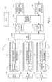
- the incoming transmission frames are received from various trunk ports and switched from the optical transceiver to transmission framers, here shown as OC-48c framers (block 60). If the incoming signals were multiplexed, they must first be de-multiplexed before the receiver. In the framers, the transmission packets or other transmission payload are removed from the OC-48c frames (de-packing) (block 62). The encapsulated PPP packet is de-capsulated by removing the flag, address, and control parameters. If the packet was scrambled before mapping, it is now unscrambled, resulting in the de-capsulated packet or segment. According to the tag on each packet, each packet is switched from the trunk to the local network (block 64).
- the resulting tagged segment has its tag stripped off (block 66), leaving the original segment. All the segments of each service are reassembled (block 68) to their original bit stream, which is passed to an interface transceiver in a service card (block 70) and sent out through the appropriate destination Service port, for transmittal to the final destination over the local network appropriate for that service.
- the end user at the access level and metro access level need not install a complicated device for converting all kinds of services data from one protocol to another for transmittal over a network. Rather, it is sufficient that it have the capability to transmit and receive services in their original protocols.
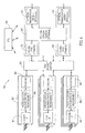
- FIG. 4 A system for transmitting services over networks according to one embodiment of the invention is shown schematically in Figs. 4 and 5.
- Service collection unit 80 includes at least one, and preferably a plurality of service cards 82.
- the number of services depends on the rate of transmission and the number of ports on the switch, as described below.
- Each service card 82 includes a service interface 84, for interfacing with a group of services, characterized by a common access protocol.
- the service collection unit is adapted to receive services in SONET, PDH, Fibre Channel, and Ethernet form.
- Service interface 84 can be, for example, an optical or electrical transceiver, such as those manufactured and sold by Lucent Technologies, New Jersey, USA, and Sumitomo Electric Lightwave, N.C.; USA for SONET and PDH services, or an Ethernet Physical interface for Ethernet and Fibre Channel services.
- the services are received through the interface as a bit stream.
- the bit stream is segmented and arranged into packets in a packetization module 86.
- Packetization module 86 can be, for example, an FPGA or ASIC for SONET and PDH services, or a MAC for Ethernet or Fibre Channel services, which divides the services into segments and packs the segments in packets for further processing, without regard to the content of the data being transmitted.
- a tagging unit 88 is provided for adding a tag to the segment.
- Tagging unit can include, for example, an FPGA for adding a connection tag including the connection identification between the traffic's source and destination end-points.
- Tagging unit 88 is coupled to an N x M packet switch 90 for switching the tagged packets to the appropriate Trunk.
- One particularly suitable packet switch is a 16 X 16 switch fabric, where each port is 2.5 Gigabits/sec, for example a fabric chipset Prizma EP (PRS 64) manufactured and marketed by IBM Corp., NY, USA. This packet switch has an aggregate bandwidth of 40 Gigabit per second, which can be filled in a flexible manner by the services.
- the operator can define how much of which service or which packets are output onto which port, so that a total of 2.5 Gigabit per second per port is reached, without being concerned in any way with the form or protocol of the original data content.
- M ports of switch 90 are usually connected to up to M trunks, each of which has an aggregate 2.5 Gigabit per second capacity.
- N ports of switch 90 are connected to N services cards. Each service card has several service ports, which can be muxed together by an appropriate multiplexer/demultiplexer. The number of such ports depends on the service port bandwidth (from 2 Megabit per second up to 1 Gbs). For example, if a service is OC-12, which has bandwidth of 622 Mbps, the number of ports could be 4, in order to fill all 2.5 Gbps aggregate input of the switch.
- the tagged segments are encapsulated into a Point-to-Point Protocol (PPP) packet in a frame, preferably a High bit rate Digital Link Control (HDLC)-like frame.
- PPP Point-to-Point Protocol
- the frame also includes a flag, to indicate the start of a transmission, source and destination address data within the communication system, control parameters, and a frame correction signal (FCS) to indicate the end of the transmission.
- FCS frame correction signal
- packet switch 90 is coupled, in turn, to a plurality of framers 92, one for each 2.5 Gb/sec bit stream.
- Each framer 92 can be, for example, a SONET OC-48c framer, catalog number VSC9112, manufactured by Vitesse Semiconductor Corp., CA, USA, or the OC-48c framer manufactured by Lucent Microelectronics, New Jersey, USA.
- the HDLC-like frames are mapped onto a payload, e.g., SONET OC-48c payload, as a transmission frame, preferably a Packet over SONET/SDH (PoS) frame, and then transported to their destination as if they were conventional PoS frames.
- a payload e.g., SONET OC-48c payload
- each transceiver 94 is preferably a 2.5Gb transceiver, such as that manufactured by Lucent Technologies, New Jersey (USA), and Sumitomo Electric Lightwave NC, (USA), or OCP Inc., CA (USA).
- 2.5 Gbps transceivers are capable of working with almost all bit rates in the desired range, for example, 10 Mbps to 2.5 Gbps.
- This bit rate (2.5 Gbps) is the most common and cost effective today, as related to SONET/SDH hierarchical systems.
- frames and bit rates related to Gigabit Internet could be used instead, such as 10 Gbps.
- WDM multiplexer If it is desired to use a WDM multiplexer in the system, different transceivers are required. While they can be the same bit rate, WDM transceivers have a different structure, and the wavelength must be specified according to DWDM related standards.
- An optional OC-48c stream switch 96 can be provided between framers 92 and transceivers 94 for switching between the various transceivers.
- One suitable stream switch is a cross-point matrix, for example the VSC834 17x17 2.5 Gb/s Cross-point Switch manufactured by Vitesse Semiconductor Corp., CA, USA.
- packet switch 90 can direct packets directly into packet frames, which are loaded on to the optical transceivers, without any intermediate transmission framers.
- an optional stream switch 96 can be coupled directly between the packet switch and the service collection unit's optical transceivers, for providing wavelength services from the packet switch to transceivers with different wavelengths.
- a CPU controller 99 is coupled to the elements of the service collection unit, to control all the various functions therein.
- the data is sent over the access or metro access network to an aggregator 100, one embodiment of which is shown in block diagram form in Fig. 5.
- Aggregator 100 serves two upstream functions: sorting the services received in OC-48 frames from a variety of service collection units, and aggregating like services for transmission on the corresponding service network, and the inverse functions (sorting services received from a service network and aggregating services according to destination) downstream. Therefore, the aggregator includes many of the same elements as the service collection unit.
- aggregator 100 includes a plurality of aggregator's optical transceivers 102, substantially similar to optical transceivers 94, for transmission to the metro backbone or metro access networks to service collection units.
- Optical transceivers 102 are coupled to a plurality of framers 104, substantially similar to framers 92.
- An optional stream switch 106 here shown as an OC-48c stream switch, can be provided between transceivers 102 and framers 104 to permit switching of frames between transceivers and framers.
- Framers 104 are coupled to an R x S packet switch 108, substantially similar to packet switch 90.
- Packet switch 108 provides switching between framers 104 and a plurality of service cards 110, each representing a different service, grouped according to type of services, as indicated by the tag on the packet. Thus, packet switch 108 performs most of the sorting of services in the aggregator.
- Each aggregator 100 includes a tagging module 112 for adding or removing the tag on a packetized service. Tagging module 112 is substantially similar to tagging module 88. Tagging modules 112 are each coupled to a packetization module 114 for segmentation of a bit stream and reassembly of segments, depending on whether the data is going upstream or downstream.
- Packetization module 114 is substantially similar to packetization module 86. Each packetization module 114 is coupled to a service interface 116. Since each service card 110 accepts a single type of service, only the interface for the appropriate interface is required on card 110. Service interfaces 116 are substantially similar to service interfaces 84.
- aggregator 100 also includes a plurality of service aggregation modules 118, 120, 122.
- service aggregation modules 118, 120, 122 In addition to the elements of the service collection unit, aggregator 100 also includes a plurality of service aggregation modules 118, 120, 122. In the illustrated embodiment, three aggregation modules are shown.
- One aggregation module is provided for aggregation of ATM services (118), which can be an ATM Multiplexer based on a switch matrix, such as the IBM "Prizma", or Lucent "Atlanta” chip set.
- Another aggregation module is provided for aggregation of IP services (120), which can be an IP switch based on, for example, Galnet2L2/L3 switch, manufactured by Galileo Technology (Israel)
- a third aggregation module is provided for aggregation of TDM services (122), which can be a TDM multiplexer /demultiplexer based on, for example, VSC8005, manufactured by Vitesse Semiconductor Corp., CA, USA. It will be appreciated that other aggregation modules can be added as required. Each aggregation module is coupled to the appropriate network for upstream and downstream transmission of data in the designated protocol.
- the services can be directly connected to the network, and no aggregation (i.e., multiplexing) is required.
- a CPU controller 124 is coupled to the elements of the aggregator, to control all the various functions therein. It will also be appreciated by those skilled in the art that the method of the present invention can be carried out by means of any suitable hardware and software.
- the system of the invention is particularly useful in the access and metro access networks.
- ONT units 80 can be efficiently utilized at the enterprise or local access level, as well as at the metro access level, while aggregators 100 are particularly useful in the metro access and metro backbone networks.
Landscapes
- Engineering & Computer Science (AREA)
- Computer Networks & Wireless Communication (AREA)
- Computer Security & Cryptography (AREA)
- Signal Processing (AREA)
- Data Exchanges In Wide-Area Networks (AREA)
- Time-Division Multiplex Systems (AREA)
- Optical Communication System (AREA)
- Devices For Conveying Motion By Means Of Endless Flexible Members (AREA)
- Steroid Compounds (AREA)
Claims (19)
- System für die Datenübertragung in Paketen über ein optisches Netzwerk, gekennzeichnet durcheine Service-Erfassungseinheit (80) miteinem Erfassungs-Modul zum Erfassen einer Vielzahl von Service-Daten, die übertragen werden sollen,einem Verarbeitungs-Modul zum Verarbeiten der Service-Leistungen in ihren Original-Protokollen in Pakete,einem Paket-Übertragungs-Modul zur Umwandlung der Service-Leistungen in optische Signale auf einem Lichtleiter zur Übertragung in ein Metro-Netzwerk, undeine Zusammenführ-Vorrichtung (100), die mit einer Vielzahl von Service-Erfassungseinheiten zur stromaufwärts und stromabwärts erfolgenden optischen Kommunikation gekoppelt sind, und miteinem Sortier-Modul zum Sortieren der Service-Leistungen aus einer Vielzahl von Paketen entsprechend dem Service-Typ, undeinem Service-Zusammenführ-Modul (118, 120, 122) zum Kombinieren gleicher Service-Leistungen für die Übertragung über ein geeignetes Service-Netzwerk.
- System nach Anspruch 1, bei dem das Paket-Übertragungsmodul einen Multiplexer/Demultiplexer zum Multiplexen/Demultiplexen gleicher Service-Leistungen auf einen Lichtleiter in einem entsprechenden Netzwerk aufweist.
- System nach Anspruch 1, bei dem das Service-Zusammenführmodul einen Multiplexer/Demultiplexer zum Multiplexen/Demultiplexen gleicher Service-Leistungen auf einen Lichtleiter in einem geeigneten Netzwerk aufweist.
- System nach einem der vorausgehenden Ansprüche, bei dem die Service-Erfassungseinheit (80) aufweist:mindestens eine Service-Schnittstelle,ein Paketbildungs-Modul zur Aufnahme von Service-Leistungen aus der Schnittstelle und zum Einführen der Service-Leistungen in Pakete,ein Markier-Modul (88) zum Markieren der Pakete, undeinen Paketschalter, der zwischen das Markier-Modul und einen Übertragungsweg eingekoppelt ist, um die Pakete an mindestens einen optischen Senderempfänger der Service-Erfassungseinheit anzukoppeln.
- System nach Anspruch 3, bei dem der optische Sendeempfänger der Service-Erfassungseinheit mindestens einen wellenlängenspezifischen Laser sowie einen Wellenlängen-Teilungs-Multiplexer/Demultiplexer WDM zum Multiplexen/Demultiplexen der Anzahl von optischen Sendeempfängern mit optischen Signalen unterschiedlicher Wellenlängen auf einen /von einem einzelnen Lichtleiter aufweist.
- System nach Anspruch 3, bei dem das Markier-Modul ein Mehrfach-Protokoll-Labelschalt-Markier-MPLS-Modul zum Hinzufügen einer Markierung auf der Basis von MPLS an jedes der Pakete ist.
- System nach Anspruch 3, bei dem ein Modul in dem Übertragungsweg zum Einkapseln der markierten Pakete in Punkt-zu-Punkt-Protokoll PPP-Pakete vorgesehen ist.
- System nach Anspruch 7, bei dem die Service-Erfassungseinheit ferner einen Stromschalter aufweist, der zwischen den Paket-Schalter und die optischen Sendeempfänger der Service-Erfassungseinheit zum Schatten von PPP-Paketen zwischen optischen Sendeempfängern gekoppelt ist.
- System nach Anspruch 7, bei dem die PPP-Pakete in einem HDLC-artigen Rahmen angeordnet sind.
- System nach Anspruch 4, bei dem die Service-Erfassungeinheit ferner mindestens einen Übertragungs-Rahmen pro Strom zum Abbilden der markierten Pakete auf Übertragungsrahmen aufweist, die zwischen dem Paket-Schalter und den optischen Sendeempfängern der Service-Erfassungseinheit gekoppelt sind.
- System nach Anspruch 10, bei dem die Übertragungs-Framer Paket-über-SONET/SDH PoS-Framer sind.
- System nach Anspruch 10, bei dem die Service-Erfassungseinheit ferner einen Stromschalter aufweist, der zwischen die Übertragungs-Framer und die Sendempfänger zum Schalten von Übertragungs-Framern zwischen Sendeempfängern gekoppelt ist.
- System nach Anspruch 10, bei dem die Erfassungs-Einheit ferner einen Stromschalter aufweist, der zwischen die Übertragungs-Framer und die optischen Sendeempfänger der Service-Erfassungseinheit zum Schalten von Übertragungs-Rahmen zwischen optischen Senderempfängern gekoppelt ist.
- System nach Anspruch 3, bei dem die Zusammenführungs-Einheit in einem Stromaufwärts-Betrieb aufweist:einen optischen Erfassungs-Sendeempfänger,einen Paket-Schalter, der als Sortier-Modul dient, um Pakete von einem Übertragungsweg aus zu richten, der in dem optischen Zusammenführungs-Sendeempfänger entsprechend der Bestimmung aufgenommen ist,ein Markier-Modul zum Entfernen einer Markierung von den Paketen, undein Service-Erfassungs-Modul zum Erfassen gleicher Serviceleistungen, wobei das Erfassungs-Modul mit einem entsprechenden Netzwerk gekoppelt ist, dasein designiertes Protokoll verwendet.
- System nach Anspruch 14, gekennzeichnet durch ein Framing-Modul, das zwischen dem optischen Sendeempfänger der Erfassimgs-Vorrichtung und dem Paket-Schalter gekoppelt ist, um Pakete aus einem Übertgragungsrahmen zu entfernen.
- System nach Anspruch 14, bei dem der optische Sendeempfänger der Service-Erfassungs-Einheit mindestens einen wellenlängenspezifischen Laser und ferner einen Wellenlängenteilungs-Multiplexer/Demultiplexer WDM zum Multiplexen/ Demultiplexen der Anzahl von optischen Sendeempfängern mit optischen Signalen unterschiedlicher Wellenlängen an einem /aus einem einzelnen Lichtleiter aufweist.
- System nach Anspruch 14, bei der das Erfassungs-Markier-Modul ein Mehrfach-Protokoll-Labelschalt MPLS-Markier-Modul ist, das eine Markierung auf der Basis von MPLS jedem der Pakete hinzufügt.
- System nach Anspruch 1, bei dem die Erfassungs-Vorrichtung in einem stromabwärts gerichteten Betrieb aufweist:einen optischen Sendeempfänger für die Erfassungs-Vorrichtung zum Aufnehmen von erfassten Serviceleistungen in ihren originalen Protokollen,ein Sortier-Modul zum Demultiplexen der empfangenen Serviceleistungen,ein Paket-Verarbeitungs-Modul zum Verarbeiten der Service-Leistungen in Pakete in einem Rahmen, Markieren, Sortieren und Multiplexen je nach der Bestimmung, unddie Service-Erfassungseinheit in einem stromabwärts gerichteten Betrieb aufweist:einen Sendeempfänger einer Service-Erfassungs-Einheit, die mit dem optischen Sendeempfänger der Erfassungs-Vorrichtung für eine stromabwärts gerichtete optische Kommunikation gekoppelt ist,ein Auspack-Modul zum Auspacken der Rahmen, so dass eine Vielzahl von Service-Paketen wieder aufgefunden werden,ein Prozessor-Modul zum Entfernen von originalen Serviceleistungen aus den Paketen, undein Übertragungs-Modul zum Übertragen von Serviceleistungen entsprechend der Bestimmung.
- System nach Anspruch 18, bei dem das Paket-Verarbeitungs-Modul ferner eine Übertragungs-Framer zum Einsetzen von verarbeiteten Paketen in Übertragungsrahmen aufweist, und
das Übertragungs-Modul so ausgelegt ist, dass es die Übertragungsrahmen auf einen Lichtleiter lädt.
Applications Claiming Priority (2)
| Application Number | Priority Date | Filing Date | Title |
|---|---|---|---|
| US09/753,513 US20020085591A1 (en) | 2001-01-03 | 2001-01-03 | Fiber optic communication system |
| US753513 | 2001-01-03 |
Publications (2)
| Publication Number | Publication Date |
|---|---|
| EP1237309A1 EP1237309A1 (de) | 2002-09-04 |
| EP1237309B1 true EP1237309B1 (de) | 2004-09-29 |
Family
ID=25030958
Family Applications (1)
| Application Number | Title | Priority Date | Filing Date |
|---|---|---|---|
| EP02075004A Expired - Lifetime EP1237309B1 (de) | 2001-01-03 | 2002-01-03 | Faseroptisches Übertragungssystem |
Country Status (4)
| Country | Link |
|---|---|
| US (1) | US20020085591A1 (de) |
| EP (1) | EP1237309B1 (de) |
| AT (1) | ATE278270T1 (de) |
| DE (1) | DE60201363T2 (de) |
Families Citing this family (11)
| Publication number | Priority date | Publication date | Assignee | Title |
|---|---|---|---|---|
| JP3627655B2 (ja) * | 2001-01-22 | 2005-03-09 | 日本電気株式会社 | アクセスネットワークシステム及びプロトコル終端装置 |
| US20020176415A1 (en) * | 2001-05-23 | 2002-11-28 | Holden Patricia Ann | Channeling protocol data units |
| US7400647B1 (en) * | 2003-01-13 | 2008-07-15 | Extreme Networks | Look up table (LUT) for point-to-point protocol identification (PPP ID) |
| US7860119B1 (en) * | 2003-12-05 | 2010-12-28 | Meriton Networks Us Inc. | SONET/SDH ring aggregation |
| US7876749B1 (en) * | 2004-11-23 | 2011-01-25 | Nortel Networks Limited | Cross-connect using ethernet multiplexors for a simple metro ethernet network |
| US8301771B2 (en) * | 2005-10-26 | 2012-10-30 | Armstrong, Quinton Co. LLC | Methods, systems, and computer program products for transmission control of sensitive application-layer data |
| US9037746B2 (en) * | 2007-05-11 | 2015-05-19 | Verizon Patent And Licensing Inc. | Pseudowire circuit emulation |
| CN102316137A (zh) * | 2010-07-07 | 2012-01-11 | 苏州彭华信息技术有限公司 | 网络开机或唤醒模块及其开机或唤醒方法 |
| CN102377813A (zh) * | 2010-08-26 | 2012-03-14 | 苏州彭华信息技术有限公司 | 自动开机或唤醒机顶盒及其开机或唤醒方法 |
| US9432751B2 (en) * | 2013-09-30 | 2016-08-30 | Microsemi Communications, Inc. | PTP transparent clock system upgrade solution |
| US10797955B2 (en) * | 2016-01-08 | 2020-10-06 | Nec Corporation | System and method for operating a network |
Family Cites Families (21)
| Publication number | Priority date | Publication date | Assignee | Title |
|---|---|---|---|---|
| US505166A (en) * | 1893-09-19 | Apparatus for treating sewage | ||
| CA1309519C (en) * | 1987-03-17 | 1992-10-27 | Antonio Cantoni | Transfer of messages in a multiplexed system |
| JP3053094B2 (ja) * | 1989-03-27 | 2000-06-19 | 株式会社日立製作所 | ディジタル信号の統計的多重化方法 |
| SE505845C2 (sv) * | 1995-04-24 | 1997-10-13 | Ericsson Telefon Ab L M | Telekommunikationssystem och sätt att överföra mikroceller i detta |
| US6172988B1 (en) * | 1996-01-31 | 2001-01-09 | Tiernan Communications, Inc. | Method for universal messaging and multiplexing of video, audio, and data streams |
| US6055277A (en) * | 1997-05-29 | 2000-04-25 | Trw Docket No. | Communication system for broadcasting to mobile users |
| EP1066735B1 (de) * | 1998-06-19 | 2011-08-17 | Juniper Networks, Inc. | Verbindungsnetzwerk zum betrieb in einem kommunikationsknoten |
| US6574238B1 (en) * | 1998-08-26 | 2003-06-03 | Intel Corporation | Inter-switch link header modification |
| GB2342823B (en) * | 1998-10-16 | 2000-11-29 | Marconi Comm Ltd | Communication system |
| US6356369B1 (en) * | 1999-02-22 | 2002-03-12 | Scientific-Atlanta, Inc. | Digital optical transmitter for processing externally generated information in the reverse path |
| US6771671B1 (en) * | 1999-03-12 | 2004-08-03 | Lucent Technologies Inc. | Data flow synchronization and ordering |
| GB2358332B (en) * | 2000-01-14 | 2002-05-29 | Marconi Comm Ltd | Method of communicating data in a communication system |
| US6810039B1 (en) * | 2000-03-30 | 2004-10-26 | Azanda Network Devices, Inc. | Processor-based architecture for facilitating integrated data transfer between both atm and packet traffic with a packet bus or packet link, including bidirectional atm-to-packet functionally for atm traffic |
| US6751224B1 (en) * | 2000-03-30 | 2004-06-15 | Azanda Network Devices, Inc. | Integrated ATM/packet segmentation-and-reassembly engine for handling both packet and ATM input data and for outputting both ATM and packet data |
| US6751214B1 (en) * | 2000-03-30 | 2004-06-15 | Azanda Network Devices, Inc. | Methods and apparatus for dynamically allocating bandwidth between ATM cells and packets |
| US6693909B1 (en) * | 2000-05-05 | 2004-02-17 | Fujitsu Network Communications, Inc. | Method and system for transporting traffic in a packet-switched network |
| US7162540B2 (en) * | 2000-05-15 | 2007-01-09 | Catchfire Systems, Inc. | Method and system for prioritizing network services |
| US6965619B2 (en) * | 2000-12-04 | 2005-11-15 | Ciena Corporation | Flexible multiplexer/demultiplexer and method for transport of optical line data to a wide/metro area link |
| US20020136223A1 (en) * | 2000-12-19 | 2002-09-26 | Ho Ka K. | Method and apparatus for interworking PNNI with the signalling and routing protocols used in MPLS networks |
| US6826201B2 (en) * | 2000-12-19 | 2004-11-30 | Nortel Networks Limited | Multiplexing SONET /SDH data streams using independent encoding schemes |
| US20020085565A1 (en) * | 2000-12-28 | 2002-07-04 | Maple Optical Systems, Inc. | Technique for time division multiplex forwarding of data streams |
-
2001
- 2001-01-03 US US09/753,513 patent/US20020085591A1/en not_active Abandoned
-
2002
- 2002-01-03 AT AT02075004T patent/ATE278270T1/de not_active IP Right Cessation
- 2002-01-03 EP EP02075004A patent/EP1237309B1/de not_active Expired - Lifetime
- 2002-01-03 DE DE60201363T patent/DE60201363T2/de not_active Expired - Fee Related
Also Published As
| Publication number | Publication date |
|---|---|
| EP1237309A1 (de) | 2002-09-04 |
| DE60201363T2 (de) | 2005-10-13 |
| US20020085591A1 (en) | 2002-07-04 |
| ATE278270T1 (de) | 2004-10-15 |
| DE60201363D1 (de) | 2004-11-04 |
Similar Documents
| Publication | Publication Date | Title |
|---|---|---|
| EP1221798A2 (de) | Paketverarbeitungsverfahren und Gerät | |
| CN100505588C (zh) | 一种光纤传输系统、光纤传输的实现方法及终端处理装置 | |
| JP3159926B2 (ja) | 同期ディジタル信号キャリアをatmディジタル信号とsonet仮想トリビュタリグループとを結合した結合信号に変換する方法および統合通信ネットワーク | |
| US6567429B1 (en) | Wide area multi-service broadband network | |
| KR100812833B1 (ko) | 서버 시스템 및 정보 전달 방법 | |
| US8654766B2 (en) | System apparatus and method for interconnecting TDM and frame/packet communication networks | |
| Callegati et al. | Packet optical networks for high-speed TCP-IP backbones | |
| US20020083190A1 (en) | Apparatus and method for GFP frame transfer | |
| WO2000046957A9 (en) | Boundary router for interconnecting communication networks across a long-haul optical network | |
| US6731876B1 (en) | Packet transmission device and packet transmission system | |
| US6834056B2 (en) | Virtual local area network protection switching | |
| EP1237309B1 (de) | Faseroptisches Übertragungssystem | |
| US6473397B1 (en) | Add/drop multiplexer and method, and Bi-directional line switcher ring featuring such multiplexers | |
| US7362777B2 (en) | Concatenated transmission of synchronous data | |
| EP1251650A2 (de) | Faseroptisches Nachrichtenübertragungsverfahren | |
| CN100488083C (zh) | 光通信网络中的业务调度装置及其方法 | |
| JP2002503056A (ja) | バーチャル・スター・ネットワーク | |
| EP1701495B1 (de) | Hybrides digitales Koppelfeld zur Vermittlung von Leitungs- und paketbasierten Datenströmen | |
| EP1081984B1 (de) | Schicht-2 "Link-handler" sowie entsprechendes Verbindungsverfahren | |
| WO2007006177A1 (fr) | Procédé et système permettant d’obtenir un multiplexage croisé et transparent conformément au protocole générique de verrouillage de trames | |
| Yang et al. | Channel statistical multiplexing in SDH/SONET networks | |
| Watanabe et al. | Robust IP backbone network utilizing WDM optical paths | |
| KR100230186B1 (ko) | 두 개의 셀 버스를 이용한 호스트 디지탈 터미널 | |
| Faulkner et al. | Efficient IP transport–architecture optimisation | |
| Shuvalov et al. | Next generation networks based on optical communication lines |
Legal Events
| Date | Code | Title | Description |
|---|---|---|---|
| PUAI | Public reference made under article 153(3) epc to a published international application that has entered the european phase |
Free format text: ORIGINAL CODE: 0009012 |
|
| AK | Designated contracting states |
Kind code of ref document: A1 Designated state(s): AT BE CH CY DE DK ES FI FR GB GR IE IT LI LU MC NL PT SE TR |
|
| AX | Request for extension of the european patent |
Free format text: AL;LT;LV;MK;RO;SI |
|
| 17P | Request for examination filed |
Effective date: 20030303 |
|
| AKX | Designation fees paid |
Designated state(s): AT BE CH CY DE DK ES FI FR GB GR IE IT LI LU MC NL PT SE TR |
|
| 17Q | First examination report despatched |
Effective date: 20030410 |
|
| GRAP | Despatch of communication of intention to grant a patent |
Free format text: ORIGINAL CODE: EPIDOSNIGR1 |
|
| GRAS | Grant fee paid |
Free format text: ORIGINAL CODE: EPIDOSNIGR3 |
|
| GRAA | (expected) grant |
Free format text: ORIGINAL CODE: 0009210 |
|
| AK | Designated contracting states |
Kind code of ref document: B1 Designated state(s): AT BE CH CY DE DK ES FI FR GB GR IE IT LI LU MC NL PT SE TR |
|
| PG25 | Lapsed in a contracting state [announced via postgrant information from national office to epo] |
Ref country code: TR Free format text: LAPSE BECAUSE OF FAILURE TO SUBMIT A TRANSLATION OF THE DESCRIPTION OR TO PAY THE FEE WITHIN THE PRESCRIBED TIME-LIMIT Effective date: 20040929 Ref country code: LI Free format text: LAPSE BECAUSE OF FAILURE TO SUBMIT A TRANSLATION OF THE DESCRIPTION OR TO PAY THE FEE WITHIN THE PRESCRIBED TIME-LIMIT Effective date: 20040929 Ref country code: FI Free format text: LAPSE BECAUSE OF FAILURE TO SUBMIT A TRANSLATION OF THE DESCRIPTION OR TO PAY THE FEE WITHIN THE PRESCRIBED TIME-LIMIT Effective date: 20040929 Ref country code: AT Free format text: LAPSE BECAUSE OF FAILURE TO SUBMIT A TRANSLATION OF THE DESCRIPTION OR TO PAY THE FEE WITHIN THE PRESCRIBED TIME-LIMIT Effective date: 20040929 Ref country code: NL Free format text: LAPSE BECAUSE OF FAILURE TO SUBMIT A TRANSLATION OF THE DESCRIPTION OR TO PAY THE FEE WITHIN THE PRESCRIBED TIME-LIMIT Effective date: 20040929 Ref country code: CH Free format text: LAPSE BECAUSE OF FAILURE TO SUBMIT A TRANSLATION OF THE DESCRIPTION OR TO PAY THE FEE WITHIN THE PRESCRIBED TIME-LIMIT Effective date: 20040929 Ref country code: BE Free format text: LAPSE BECAUSE OF FAILURE TO SUBMIT A TRANSLATION OF THE DESCRIPTION OR TO PAY THE FEE WITHIN THE PRESCRIBED TIME-LIMIT Effective date: 20040929 |
|
| REG | Reference to a national code |
Ref country code: GB Ref legal event code: FG4D |
|
| REG | Reference to a national code |
Ref country code: CH Ref legal event code: EP |
|
| REG | Reference to a national code |
Ref country code: IE Ref legal event code: FG4D |
|
| REF | Corresponds to: |
Ref document number: 60201363 Country of ref document: DE Date of ref document: 20041104 Kind code of ref document: P |
|
| PG25 | Lapsed in a contracting state [announced via postgrant information from national office to epo] |
Ref country code: DK Free format text: LAPSE BECAUSE OF FAILURE TO SUBMIT A TRANSLATION OF THE DESCRIPTION OR TO PAY THE FEE WITHIN THE PRESCRIBED TIME-LIMIT Effective date: 20041229 Ref country code: GR Free format text: LAPSE BECAUSE OF FAILURE TO SUBMIT A TRANSLATION OF THE DESCRIPTION OR TO PAY THE FEE WITHIN THE PRESCRIBED TIME-LIMIT Effective date: 20041229 |
|
| PG25 | Lapsed in a contracting state [announced via postgrant information from national office to epo] |
Ref country code: LU Free format text: LAPSE BECAUSE OF NON-PAYMENT OF DUE FEES Effective date: 20050103 Ref country code: CY Free format text: LAPSE BECAUSE OF FAILURE TO SUBMIT A TRANSLATION OF THE DESCRIPTION OR TO PAY THE FEE WITHIN THE PRESCRIBED TIME-LIMIT Effective date: 20050103 Ref country code: IE Free format text: LAPSE BECAUSE OF NON-PAYMENT OF DUE FEES Effective date: 20050103 |
|
| PG25 | Lapsed in a contracting state [announced via postgrant information from national office to epo] |
Ref country code: ES Free format text: LAPSE BECAUSE OF FAILURE TO SUBMIT A TRANSLATION OF THE DESCRIPTION OR TO PAY THE FEE WITHIN THE PRESCRIBED TIME-LIMIT Effective date: 20050109 |
|
| REG | Reference to a national code |
Ref country code: SE Ref legal event code: TRGR |
|
| PG25 | Lapsed in a contracting state [announced via postgrant information from national office to epo] |
Ref country code: MC Free format text: LAPSE BECAUSE OF NON-PAYMENT OF DUE FEES Effective date: 20050131 |
|
| NLV1 | Nl: lapsed or annulled due to failure to fulfill the requirements of art. 29p and 29m of the patents act | ||
| REG | Reference to a national code |
Ref country code: CH Ref legal event code: PL |
|
| ET | Fr: translation filed | ||
| PLBE | No opposition filed within time limit |
Free format text: ORIGINAL CODE: 0009261 |
|
| STAA | Information on the status of an ep patent application or granted ep patent |
Free format text: STATUS: NO OPPOSITION FILED WITHIN TIME LIMIT |
|
| 26N | No opposition filed |
Effective date: 20050630 |
|
| REG | Reference to a national code |
Ref country code: IE Ref legal event code: MM4A |
|
| PGFP | Annual fee paid to national office [announced via postgrant information from national office to epo] |
Ref country code: DE Payment date: 20070110 Year of fee payment: 6 |
|
| PGFP | Annual fee paid to national office [announced via postgrant information from national office to epo] |
Ref country code: SE Payment date: 20070111 Year of fee payment: 6 |
|
| PGFP | Annual fee paid to national office [announced via postgrant information from national office to epo] |
Ref country code: GB Payment date: 20070119 Year of fee payment: 6 |
|
| PG25 | Lapsed in a contracting state [announced via postgrant information from national office to epo] |
Ref country code: PT Free format text: LAPSE BECAUSE OF NON-PAYMENT OF DUE FEES Effective date: 20050228 |
|
| PGFP | Annual fee paid to national office [announced via postgrant information from national office to epo] |
Ref country code: IT Payment date: 20070623 Year of fee payment: 6 |
|
| PGFP | Annual fee paid to national office [announced via postgrant information from national office to epo] |
Ref country code: FR Payment date: 20070111 Year of fee payment: 6 |
|
| EUG | Se: european patent has lapsed | ||
| GBPC | Gb: european patent ceased through non-payment of renewal fee |
Effective date: 20080103 |
|
| PG25 | Lapsed in a contracting state [announced via postgrant information from national office to epo] |
Ref country code: DE Free format text: LAPSE BECAUSE OF NON-PAYMENT OF DUE FEES Effective date: 20080801 |
|
| REG | Reference to a national code |
Ref country code: FR Ref legal event code: ST Effective date: 20081029 |
|
| PG25 | Lapsed in a contracting state [announced via postgrant information from national office to epo] |
Ref country code: GB Free format text: LAPSE BECAUSE OF NON-PAYMENT OF DUE FEES Effective date: 20080103 |
|
| PG25 | Lapsed in a contracting state [announced via postgrant information from national office to epo] |
Ref country code: SE Free format text: LAPSE BECAUSE OF NON-PAYMENT OF DUE FEES Effective date: 20080104 |
|
| PG25 | Lapsed in a contracting state [announced via postgrant information from national office to epo] |
Ref country code: FR Free format text: LAPSE BECAUSE OF NON-PAYMENT OF DUE FEES Effective date: 20080131 |
|
| PG25 | Lapsed in a contracting state [announced via postgrant information from national office to epo] |
Ref country code: IT Free format text: LAPSE BECAUSE OF NON-PAYMENT OF DUE FEES Effective date: 20080103 |