EP1238595A2 - Armure corporelle en particulier contre les coupures - Google Patents
Armure corporelle en particulier contre les coupures Download PDFInfo
- Publication number
- EP1238595A2 EP1238595A2 EP02005152A EP02005152A EP1238595A2 EP 1238595 A2 EP1238595 A2 EP 1238595A2 EP 02005152 A EP02005152 A EP 02005152A EP 02005152 A EP02005152 A EP 02005152A EP 1238595 A2 EP1238595 A2 EP 1238595A2
- Authority
- EP
- European Patent Office
- Prior art keywords
- body armor
- closure element
- armor according
- elements
- flange part
- Prior art date
- Legal status (The legal status is an assumption and is not a legal conclusion. Google has not performed a legal analysis and makes no representation as to the accuracy of the status listed.)
- Granted
Links
Images


Classifications
-
- F—MECHANICAL ENGINEERING; LIGHTING; HEATING; WEAPONS; BLASTING
- F41—WEAPONS
- F41H—ARMOUR; ARMOURED TURRETS; ARMOURED OR ARMED VEHICLES; MEANS OF ATTACK OR DEFENCE, e.g. CAMOUFLAGE, IN GENERAL
- F41H5/00—Armour; Armour plates
- F41H5/02—Plate construction
- F41H5/04—Plate construction composed of more than one layer
- F41H5/0492—Layered armour containing hard elements, e.g. plates, spheres, rods, separated from each other, the elements being connected to a further flexible layer or being embedded in a plastics or an elastomer matrix
-
- A—HUMAN NECESSITIES
- A41—WEARING APPAREL
- A41D—OUTERWEAR; PROTECTIVE GARMENTS; ACCESSORIES
- A41D31/00—Materials specially adapted for outerwear
- A41D31/04—Materials specially adapted for outerwear characterised by special function or use
- A41D31/24—Resistant to mechanical stress, e.g. pierce-proof
Definitions
- the invention relates to body armor, in particular for the Stab protection, with the features of the preamble of claim 1.
- DE 296 05 503 U1 already provides body armor for the shoulder joint zone known.
- This body armor exists essentially from several armor plates shaped to fit the body, which are made of deep-drawn light metal sheet.
- the following Armor plates referred to as surface elements are articulated with one another connected. This means not only extensive body protection, but also good mobility of the body armor achieved, which is a good wearing comfort with high freedom of movement is achieved.
- On the surface element arranged on the shoulder are surface elements over joints for the protection of the clavicle and the shoulder blade arranged. These joints are considered elongated Hinges formed.
- These flexible surface elements consist of ring elements movably connected to each other.
- the ring elements are partially in line with the Adjacent ring elements projecting or overlapping.
- Such a surface element is, for example, from DE 198 33 816 A1 known, which is characterized in that the individual ring elements have at least one passage which is designed such that each ring element on at least two further ring elements can be attached by loops made of a thread-like material.
- scale-like stab protection fabrics are known from DE 198 19 737 A1 known that are used to protect a person Prevent puncture by an ice ax or stickleback.
- This stab protection fabric consists of a large number of interconnected Scales which have holes for connection to one another, engage in the fasteners. The scales overlap tile roof-like and the connecting elements are directly on the Molded scales.
- the present invention is based on this prior art the task of creating body armor, the improved security features, especially a better one Stab protection, while maintaining sufficient or achieving an even has improved comfort.
- a closure element is arranged so that on the one hand the Mobility of body armor through the connection of the individual Surface elements over the joints are preserved and at the same time by closing the existing between the surface elements Gap opening also in the connection area of the stab protection, in particular with regard to an angle cut, is improved.
- the closure elements are preferably made from an extrusion process elastic plastic, preferably EPDM (ethylene-propylene-diene rubber), manufactured and have the shape of long profiles. hereby is the mobility of the individual surface elements that the Determine the wearing comfort of the body armor.
- EPDM ethylene-propylene-diene rubber
- At least one reinforcing part is preferably in the closure element embedded that the stomata of a carrier of the Body armor facing away from the outside. hereby the stab protection in the area of the gap opening can be further improved.
- the reinforcing part is preferably designed as a flat profile and made of steel, preferably VA steel.
- the closure element has a H-shaped cross section.
- two U-shaped openings are then each opposite arranged surface elements with their edge areas inserted. This ensures that after the joints have been assembled the closure element between two without further attachment adjacent surface elements is held.
- the H-shaped closure element has an upper one Flange part, a web part and lower flange part.
- the reinforcement part is embedded in the flange part. More reinforcement parts can also be embedded in the web part and / or the lower flange part his.
- the several reinforcement parts are each through separated the material of the closure element. Through the several reinforcement parts will further increase the stab protection reached.
- the upper flange part and lower flange part designed so that these in the installed state with their Surfaces facing the U-shaped opening closely to the surface element issue. In the non-installed state, they project laterally from the web part opposite ends of the upper flange part in the U-shaped openings into it so that it is clamped in the installed state and attached to the surface elements be pressed. This prevents the closure element even at different angular positions of the surface elements to each other as a result of movements of the wearer from the Surface of the surface elements stands out. So a blade becomes one Stab successfully deflected from the breech element and slides then along the top of the upper flange part.
- the closure elements themselves can serve as joints, in particular if they are sufficiently firmly connected to the surface elements.
- separate joints like hinge joints.
- This ring element is preferably made of one Flat profile formed. Then have those provided in the surface elements Openings in the form of a flat rectangle. In the closed, i.e. pressed, state, the ring elements have the cross section an elongated O on.
- the preferred material for the Ring elements and the reinforcing elements steel preferably VA steel, used.
- the surface elements themselves are advantageously suitable for the body molded plates and designed to increase comfort Light metal, preferably made of aluminum.
- 1 shows a plan view of a section of body armor, which are connected to one another by a large number of joints 1
- Surface elements 2 exist. 1 shows an example only sections of two interconnected surface elements 2, to which there are 1 additional surface elements at further edges via further joints can connect.
- the individual surface elements 1 are each made of light metal, preferably aluminum and are made to measure for the respective wearer shaped and their size and shape tailored accordingly that the mobility of the body armor by a Body movements of the wearer following arrangement of the joints 1 between the individual surface elements 2 results.
- the plate-shaped surface elements 2 are formed as in FIG. 1 a gap opening 3 via joints 1 in the manner of a hinge joint connected with each other.
- the joint 1 consists essentially from in the border area 4 of the surface element adjacent to the gap opening 3 2 arranged openings 5 which have a cross section of a have flat rectangle, the longitudinal extension of which is parallel to Longitudinal extension of the gap opening 3 extends.
- These openings 5 are arranged opposite each other in both surface elements 2 and serve to receive a ring element 6, which consists of a section an elongated flat profile is formed. For the assembly it will be open, U-shaped ring element 6 through the two opposite Openings 5 pushed through and compressed to form the ring element 6.
- the ring element 6 thus has in the installed state Cross-section seen a stadium-shaped shape and thus contributes to the remaining surface element 2 hardly.
- the openings 5 and the ring elements 6 are as close as possible in the end region of the gap opening 3 arranged.
- the length of the remaining gap opening 3 corresponds approximately the width of the ring element. Due to the design of the stadium-shaped Ring element 6 and the corresponding dimensioning of the opening 5 will also provide adequate stab protection in the area of joint 1 reached, although a small gap 7 between the ring element 6 and the adjacent surface element 2 remains. This gap points but less than 1 mm wide.
- the located between the two ring elements 6 of the Slit opening 3 is additionally against the closure element 8 Penetration of a stab of a stab weapon secured.
- This closure element 8 is on before joining the two surface elements 2 an edge area 4 of a surface element 2 is pushed on and then the other surface element 2 is inserted into the closure element 8. Then, as previously described, the ring elements 6 mounted.
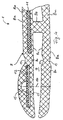
- the closure element 8 is essentially H-shaped with an upper flange part 80, a lower flange part 8u and a web part 8s.
- the upper flange part 80, the web part 8s and the lower one Flange part 8u thus form two U-shaped openings 9, which are starting in the opposite direction from the web part 8s.
- the surface elements 2 of the body armor are in each of these openings 9 pushed in as far as possible against the web part 8s. in the The reason for the opening 9 are in the corner areas each of manufacturing technology Reasons round recesses 10 available.
- the closure element 8 is made of an elastic plastic, preferably made of EPDM (ethylene-propylene-diene rubber) in the area of its upper flange part 80 additionally via a reinforcing element 11 secured against piercing.
- the width of the reinforcing element 11 corresponds to at least three times the width of the Gap opening 3.
- This reinforcing element 11 is made of steel, preferably made of VA steel and is according to the straight shape the gap opening, following the course of the gap opening, as a straight line Flat profile trained.
- the width of the flat profile-shaped closure element 8 is selected that the gap opening 3 laterally at least twice the gap opening is covered. It is therefore safe even with a 25 ° angle cut ensures that the blade of a stab weapon does not enter the gap opening 3 can penetrate between two adjacent surface elements 2.
- the Reinforcing element 11 is surrounded on all sides by plastic and thus in the closure element 8 embedded. The mobility of the surface elements 2 is therefore retained.
- the upper flange part 8o and the lower Flange part 8u with their respective inner side 8i close to the surface of the surface element 2.
- the outside 8a of the top Flange part 80 and the lower flange part 8u is in the area of its lateral End regions 8e starting from the web part 8s to the surface of the surface element 2 formed sloping.
- the further Fig. 3 shows a closure element 8, as in Fig. 2, however not when installed. It can also be seen that in addition to that, too 2, reinforcing element 11 present in the upper flange part further reinforcing elements 11 in the web part 8s and the lower one Flange part 8u are provided. This serves to improve puncture resistance. All reinforcing elements 11 are made of steel, preferably made of VA steel, separated from each other and on all sides surrounded by plastic embedded in the closure element 8. hereby becomes the flexibility of the connection between the surface elements 2 received. In addition to the variant shown with three reinforcement elements 11 is also any other combination of reinforcing elements 11 possible if the function is retained that a puncture protection is maintained in the area of the gap opening 3.
- the support element 12 serves as a support for a connecting element 14, such as a hollow rivet, which has a fixed Connection between the closure element and the adjacent surface element manufactures.
Landscapes
- Engineering & Computer Science (AREA)
- General Engineering & Computer Science (AREA)
- Aiming, Guidance, Guns With A Light Source, Armor, Camouflage, And Targets (AREA)
- Medical Preparation Storing Or Oral Administration Devices (AREA)
- Seal Device For Vehicle (AREA)
- Materials For Medical Uses (AREA)
- Building Environments (AREA)
Applications Claiming Priority (2)
| Application Number | Priority Date | Filing Date | Title |
|---|---|---|---|
| DE10110851 | 2001-03-07 | ||
| DE10110851A DE10110851C1 (de) | 2001-03-07 | 2001-03-07 | Körperschutzpanzerung, insbesondere für den Stichschutz |
Publications (3)
| Publication Number | Publication Date |
|---|---|
| EP1238595A2 true EP1238595A2 (fr) | 2002-09-11 |
| EP1238595A3 EP1238595A3 (fr) | 2004-01-07 |
| EP1238595B1 EP1238595B1 (fr) | 2007-07-18 |
Family
ID=7676545
Family Applications (1)
| Application Number | Title | Priority Date | Filing Date |
|---|---|---|---|
| EP02005152A Expired - Lifetime EP1238595B1 (fr) | 2001-03-07 | 2002-03-07 | Armure corporelle en particulier contre les coupures |
Country Status (4)
| Country | Link |
|---|---|
| EP (1) | EP1238595B1 (fr) |
| AT (1) | ATE367102T1 (fr) |
| DE (2) | DE10110851C1 (fr) |
| ES (1) | ES2290210T3 (fr) |
Cited By (2)
| Publication number | Priority date | Publication date | Assignee | Title |
|---|---|---|---|---|
| EP1787537A3 (fr) * | 2005-11-18 | 2011-05-25 | Lothar Müller | Armure corporelle, en particulier contre les coupures |
| DE102016202546A1 (de) | 2016-02-18 | 2017-08-24 | Deutsche Institute Für Textil- Und Faserforschung Denkendorf | Verbundstruktur für den Stichschutz, Verfahren zur Herstellung einer Verbundstruktur, Stichschutzeinlage sowie Schutztextil |
Families Citing this family (2)
| Publication number | Priority date | Publication date | Assignee | Title |
|---|---|---|---|---|
| DE202018002267U1 (de) | 2018-05-08 | 2019-08-13 | Mk Technology Gmbh | Verbindungselement für eine Körperschutzpanzerung, insbesondere für den Schlag- und/oder Stichschutz, sowie Körperschutzpanzerung |
| DE202018002721U1 (de) | 2018-06-08 | 2019-09-10 | Mk Technology Gmbh | H-Profil für eine Körperschutzpanzerung, insbesondere für den Stichschutz, sowie Körperschutzpanzerung |
Family Cites Families (12)
| Publication number | Priority date | Publication date | Assignee | Title |
|---|---|---|---|---|
| US2373726A (en) * | 1942-08-14 | 1945-04-17 | George L Watts | Armored garment |
| FR2558249A1 (fr) * | 1984-01-12 | 1985-07-19 | Fonderie Alcoa Mg Sa | Elements de blindage, et blindages souples constitues a partir de tels elements, notamment gilets pare-balles |
| DE3940624A1 (de) * | 1989-12-08 | 1991-06-13 | Sst Sicherheits Und Systemtech | Panzerplattenanordnung mit abdeckgitter |
| GB9105233D0 (en) * | 1991-03-12 | 1991-04-24 | Bryant Lionel | Flexible body armour |
| DE4208308C2 (de) * | 1992-03-16 | 1995-04-20 | Akzo Nobel Faser Ag | Gehäuse zum ballistischen Schutz von Personen und/oder Objekten |
| US5670734A (en) * | 1994-10-05 | 1997-09-23 | United Defense, L.P. | Modular armor mounting system |
| GB2303534B (en) * | 1995-07-22 | 1998-10-28 | Tba Industrial Products Ltd | Armour |
| DE29513029U1 (de) * | 1995-08-17 | 1996-02-01 | Sitek GmbH, 30900 Wedemark | Am Körper zu tragende Schutzvorrichtung |
| DE29605503U1 (de) * | 1996-03-25 | 1996-09-05 | Müller, Lothar, 58513 Lüdenscheid | Körperschutzpanzerung und Körperschutzweste oder -jacke hierfür |
| US5915528A (en) * | 1997-12-23 | 1999-06-29 | Shmuelov; Elyahu | Protective stripe assemblies with concave-convex interfaces |
| DE19819737C2 (de) * | 1998-05-04 | 2000-02-17 | Ziegler Mechanische Werkstatt Metallgewebe & Arbeitsschutz Gmbh | Gewebe, insbesondere Stichschutzgewebe |
| DE19833816A1 (de) * | 1998-07-28 | 2000-03-02 | Wissens Und Technologietransfe | Flexible Schutzfläche zum vorzugsweisen Einsatz im Personenschutz |
-
2001
- 2001-03-07 DE DE10110851A patent/DE10110851C1/de not_active Expired - Lifetime
-
2002
- 2002-03-07 ES ES02005152T patent/ES2290210T3/es not_active Expired - Lifetime
- 2002-03-07 AT AT02005152T patent/ATE367102T1/de active
- 2002-03-07 DE DE50210477T patent/DE50210477D1/de not_active Expired - Lifetime
- 2002-03-07 EP EP02005152A patent/EP1238595B1/fr not_active Expired - Lifetime
Cited By (4)
| Publication number | Priority date | Publication date | Assignee | Title |
|---|---|---|---|---|
| EP1787537A3 (fr) * | 2005-11-18 | 2011-05-25 | Lothar Müller | Armure corporelle, en particulier contre les coupures |
| DE102016202546A1 (de) | 2016-02-18 | 2017-08-24 | Deutsche Institute Für Textil- Und Faserforschung Denkendorf | Verbundstruktur für den Stichschutz, Verfahren zur Herstellung einer Verbundstruktur, Stichschutzeinlage sowie Schutztextil |
| WO2017140908A1 (fr) | 2016-02-18 | 2017-08-24 | Deutsche Institute Für Textil- Und Faserforschung Denkendorf | Structure composite pour une protection anti-perforation, procédé de fabrication d'une structure composite, entoilage de protection anti-perforation et textile protecteur |
| US10869513B2 (en) | 2016-02-18 | 2020-12-22 | Deutsche Institute Für Textil-Und Faserforschung Denkendorf | Stabbing-proof composite structure, method of manufacturing a composite structure, stabbing-proof insert, and protective textile |
Also Published As
| Publication number | Publication date |
|---|---|
| EP1238595A3 (fr) | 2004-01-07 |
| ES2290210T3 (es) | 2008-02-16 |
| DE10110851C1 (de) | 2002-05-29 |
| EP1238595B1 (fr) | 2007-07-18 |
| DE50210477D1 (de) | 2007-08-30 |
| ATE367102T1 (de) | 2007-08-15 |
Similar Documents
| Publication | Publication Date | Title |
|---|---|---|
| EP3516147B1 (fr) | Porte à enroulement à l'épreuve des balles | |
| DE3537964C1 (de) | Kabelfuehrung fuer Kraftfahrzeug-Schiebedaecher | |
| EP1057424A2 (fr) | Dispositif de fermeture pour les ouvertures d'une combinaison de sports aquatiques | |
| DE2030533A1 (de) | Zusammengesetzte Blattfeder | |
| DE2701905C3 (de) | Stranggeprefites Bauelement zum Aufbau von Wänden, insbesondere von Kraftfahrzeugen | |
| EP1803878B1 (fr) | Fermeture de décompression | |
| AT413829B (de) | Vorrichtung zum überbrücken von dehnfugen in fahrbahnen | |
| DE69412269T2 (de) | Schutzbahn hergestellt aus mit ringen verbundenen platten sowie schürzen daraus gefertigt | |
| EP0992383B1 (fr) | Système de porte pour véhicules utilitaires | |
| DE20220812U1 (de) | Abdeckvorrichtung für Gleit- und Führungsbahnen von Maschinen | |
| DE202007000020U1 (de) | Türblatt, vorzugsweise für eine Hauseingangstür | |
| EP1104722B1 (fr) | Elément de déformation pour l'intérieur d'un véhicule, à insérer dans une cavité, en particulier | |
| EP1238595A2 (fr) | Armure corporelle en particulier contre les coupures | |
| DE69811873T2 (de) | Türkonstruktion | |
| DE3326763A1 (de) | Tuerband | |
| EP1568833A2 (fr) | Gâche pour une fenêtre ou une porte | |
| EP1487688A1 (fr) | Aile de voiture en matiere plastique et dispositif de fixation associe | |
| DE10146615B4 (de) | Laschenverbindung | |
| DE202014004827U1 (de) | Rückensteife Schubkette | |
| DE202022102549U1 (de) | Metallband | |
| EP1787537B1 (fr) | Armure corporelle, en particulier contre les coupures | |
| DE2703111C3 (fr) | ||
| DE20000335U1 (de) | Vorsatztür oder -fenster, insbesondere Insektenschutzgitter | |
| DE69101580T2 (de) | Profilverstärkungskern, insbesondere zum Gebrauch in der Kraftfahrzeugindustrie. | |
| AT407653B (de) | Schwenkhebel-betätigungsvorrichtung für treibstangenbeschläge |
Legal Events
| Date | Code | Title | Description |
|---|---|---|---|
| PUAI | Public reference made under article 153(3) epc to a published international application that has entered the european phase |
Free format text: ORIGINAL CODE: 0009012 |
|
| AK | Designated contracting states |
Kind code of ref document: A2 Designated state(s): AT BE CH CY DE DK ES FI FR GB GR IE IT LI LU MC NL PT SE TR |
|
| AX | Request for extension of the european patent |
Free format text: AL;LT;LV;MK;RO;SI |
|
| PUAL | Search report despatched |
Free format text: ORIGINAL CODE: 0009013 |
|
| AK | Designated contracting states |
Kind code of ref document: A3 Designated state(s): AT BE CH CY DE DK ES FI FR GB GR IE IT LI LU MC NL PT SE TR |
|
| AX | Request for extension of the european patent |
Extension state: AL LT LV MK RO SI |
|
| 17P | Request for examination filed |
Effective date: 20040707 |
|
| AKX | Designation fees paid |
Designated state(s): AT BE CH CY DE DK ES FI FR GB GR IE IT LI LU MC NL PT SE TR |
|
| AXX | Extension fees paid |
Extension state: RO Payment date: 20040707 Extension state: LV Payment date: 20040707 Extension state: LT Payment date: 20040707 Extension state: MK Payment date: 20040707 Extension state: SI Payment date: 20040707 |
|
| GRAP | Despatch of communication of intention to grant a patent |
Free format text: ORIGINAL CODE: EPIDOSNIGR1 |
|
| GRAS | Grant fee paid |
Free format text: ORIGINAL CODE: EPIDOSNIGR3 |
|
| GRAA | (expected) grant |
Free format text: ORIGINAL CODE: 0009210 |
|
| AK | Designated contracting states |
Kind code of ref document: B1 Designated state(s): AT BE CH CY DE DK ES FI FR GB GR IE IT LI LU MC NL PT SE TR |
|
| AX | Request for extension of the european patent |
Extension state: LT LV MK RO SI |
|
| REG | Reference to a national code |
Ref country code: GB Ref legal event code: FG4D Free format text: NOT ENGLISH |
|
| REG | Reference to a national code |
Ref country code: CH Ref legal event code: EP |
|
| REF | Corresponds to: |
Ref document number: 50210477 Country of ref document: DE Date of ref document: 20070830 Kind code of ref document: P |
|
| REG | Reference to a national code |
Ref country code: IE Ref legal event code: FG4D Free format text: LANGUAGE OF EP DOCUMENT: GERMAN |
|
| REG | Reference to a national code |
Ref country code: SE Ref legal event code: TRGR Ref country code: CH Ref legal event code: NV Representative=s name: E. BLUM & CO. AG PATENT- UND MARKENANWAELTE VSP |
|
| LTIE | Lt: invalidation of european patent or patent extension |
Effective date: 20070718 |
|
| PG25 | Lapsed in a contracting state [announced via postgrant information from national office to epo] |
Ref country code: FI Free format text: LAPSE BECAUSE OF FAILURE TO SUBMIT A TRANSLATION OF THE DESCRIPTION OR TO PAY THE FEE WITHIN THE PRESCRIBED TIME-LIMIT Effective date: 20070718 Ref country code: PT Free format text: LAPSE BECAUSE OF FAILURE TO SUBMIT A TRANSLATION OF THE DESCRIPTION OR TO PAY THE FEE WITHIN THE PRESCRIBED TIME-LIMIT Effective date: 20071218 |
|
| GBV | Gb: ep patent (uk) treated as always having been void in accordance with gb section 77(7)/1977 [no translation filed] |
Effective date: 20070718 |
|
| REG | Reference to a national code |
Ref country code: ES Ref legal event code: FG2A Ref document number: 2290210 Country of ref document: ES Kind code of ref document: T3 |
|
| REG | Reference to a national code |
Ref country code: IE Ref legal event code: FD4D |
|
| EN | Fr: translation not filed | ||
| PG25 | Lapsed in a contracting state [announced via postgrant information from national office to epo] |
Ref country code: GR Free format text: LAPSE BECAUSE OF FAILURE TO SUBMIT A TRANSLATION OF THE DESCRIPTION OR TO PAY THE FEE WITHIN THE PRESCRIBED TIME-LIMIT Effective date: 20071019 Ref country code: DK Free format text: LAPSE BECAUSE OF FAILURE TO SUBMIT A TRANSLATION OF THE DESCRIPTION OR TO PAY THE FEE WITHIN THE PRESCRIBED TIME-LIMIT Effective date: 20070718 |
|
| PLBE | No opposition filed within time limit |
Free format text: ORIGINAL CODE: 0009261 |
|
| STAA | Information on the status of an ep patent application or granted ep patent |
Free format text: STATUS: NO OPPOSITION FILED WITHIN TIME LIMIT |
|
| PG25 | Lapsed in a contracting state [announced via postgrant information from national office to epo] |
Ref country code: IE Free format text: LAPSE BECAUSE OF FAILURE TO SUBMIT A TRANSLATION OF THE DESCRIPTION OR TO PAY THE FEE WITHIN THE PRESCRIBED TIME-LIMIT Effective date: 20070718 Ref country code: GB Free format text: LAPSE BECAUSE OF FAILURE TO SUBMIT A TRANSLATION OF THE DESCRIPTION OR TO PAY THE FEE WITHIN THE PRESCRIBED TIME-LIMIT Effective date: 20070718 |
|
| 26N | No opposition filed |
Effective date: 20080421 |
|
| PG25 | Lapsed in a contracting state [announced via postgrant information from national office to epo] |
Ref country code: FR Free format text: LAPSE BECAUSE OF FAILURE TO SUBMIT A TRANSLATION OF THE DESCRIPTION OR TO PAY THE FEE WITHIN THE PRESCRIBED TIME-LIMIT Effective date: 20080314 |
|
| BERE | Be: lapsed |
Owner name: MULLER, LOTHAR Effective date: 20080331 |
|
| PG25 | Lapsed in a contracting state [announced via postgrant information from national office to epo] |
Ref country code: MC Free format text: LAPSE BECAUSE OF NON-PAYMENT OF DUE FEES Effective date: 20080331 |
|
| PG25 | Lapsed in a contracting state [announced via postgrant information from national office to epo] |
Ref country code: BE Free format text: LAPSE BECAUSE OF NON-PAYMENT OF DUE FEES Effective date: 20080331 |
|
| PG25 | Lapsed in a contracting state [announced via postgrant information from national office to epo] |
Ref country code: CY Free format text: LAPSE BECAUSE OF FAILURE TO SUBMIT A TRANSLATION OF THE DESCRIPTION OR TO PAY THE FEE WITHIN THE PRESCRIBED TIME-LIMIT Effective date: 20070718 |
|
| NLV4 | Nl: lapsed or anulled due to non-payment of the annual fee |
Effective date: 20091001 |
|
| NLXE | Nl: other communications concerning ep-patents (part 3 heading xe) |
Free format text: A REQUEST FOR RESTORATION TO THE PRIOR STATE (ARTICLE 23 OF THE PATENTS ACT 1995) HAS BEEN FILED ON 20091208 |
|
| PG25 | Lapsed in a contracting state [announced via postgrant information from national office to epo] |
Ref country code: NL Free format text: LAPSE BECAUSE OF NON-PAYMENT OF DUE FEES Effective date: 20091001 |
|
| PG25 | Lapsed in a contracting state [announced via postgrant information from national office to epo] |
Ref country code: LU Free format text: LAPSE BECAUSE OF NON-PAYMENT OF DUE FEES Effective date: 20080307 |
|
| REG | Reference to a national code |
Ref country code: NL Ref legal event code: RD1H Effective date: 20091208 |
|
| REG | Reference to a national code |
Ref country code: NL Ref legal event code: RD1H Effective date: 20091208 |
|
| REG | Reference to a national code |
Ref country code: NL Ref legal event code: RD1H Effective date: 20091208 |
|
| REG | Reference to a national code |
Ref country code: NL Ref legal event code: RD1H Effective date: 20091208 |
|
| PG25 | Lapsed in a contracting state [announced via postgrant information from national office to epo] |
Ref country code: IT Free format text: LAPSE BECAUSE OF NON-PAYMENT OF DUE FEES Effective date: 20080331 |
|
| PGRI | Patent reinstated in contracting state [announced from national office to epo] |
Ref country code: NL Effective date: 20110121 |
|
| PG25 | Lapsed in a contracting state [announced via postgrant information from national office to epo] |
Ref country code: DE Free format text: LAPSE BECAUSE OF NON-PAYMENT OF DUE FEES Effective date: 20111001 |
|
| PGRI | Patent reinstated in contracting state [announced from national office to epo] |
Ref country code: DE Effective date: 20120114 |
|
| PGFP | Annual fee paid to national office [announced via postgrant information from national office to epo] |
Ref country code: SE Payment date: 20200325 Year of fee payment: 19 Ref country code: AT Payment date: 20200319 Year of fee payment: 19 Ref country code: NL Payment date: 20200323 Year of fee payment: 19 |
|
| PGFP | Annual fee paid to national office [announced via postgrant information from national office to epo] |
Ref country code: CH Payment date: 20200325 Year of fee payment: 19 |
|
| PGFP | Annual fee paid to national office [announced via postgrant information from national office to epo] |
Ref country code: TR Payment date: 20200304 Year of fee payment: 19 |
|
| PGFP | Annual fee paid to national office [announced via postgrant information from national office to epo] |
Ref country code: ES Payment date: 20200421 Year of fee payment: 19 Ref country code: DE Payment date: 20200529 Year of fee payment: 19 |
|
| REG | Reference to a national code |
Ref country code: DE Ref legal event code: R119 Ref document number: 50210477 Country of ref document: DE |
|
| REG | Reference to a national code |
Ref country code: CH Ref legal event code: PL |
|
| REG | Reference to a national code |
Ref country code: NL Ref legal event code: MM Effective date: 20210401 |
|
| REG | Reference to a national code |
Ref country code: AT Ref legal event code: MM01 Ref document number: 367102 Country of ref document: AT Kind code of ref document: T Effective date: 20210307 |
|
| PG25 | Lapsed in a contracting state [announced via postgrant information from national office to epo] |
Ref country code: LI Free format text: LAPSE BECAUSE OF NON-PAYMENT OF DUE FEES Effective date: 20210331 Ref country code: CH Free format text: LAPSE BECAUSE OF NON-PAYMENT OF DUE FEES Effective date: 20210331 Ref country code: AT Free format text: LAPSE BECAUSE OF NON-PAYMENT OF DUE FEES Effective date: 20210307 Ref country code: NL Free format text: LAPSE BECAUSE OF NON-PAYMENT OF DUE FEES Effective date: 20210401 Ref country code: SE Free format text: LAPSE BECAUSE OF NON-PAYMENT OF DUE FEES Effective date: 20210308 Ref country code: DE Free format text: LAPSE BECAUSE OF NON-PAYMENT OF DUE FEES Effective date: 20211001 |
|
| REG | Reference to a national code |
Ref country code: ES Ref legal event code: FD2A Effective date: 20220523 |
|
| PG25 | Lapsed in a contracting state [announced via postgrant information from national office to epo] |
Ref country code: ES Free format text: LAPSE BECAUSE OF NON-PAYMENT OF DUE FEES Effective date: 20210308 |