EP1239112B1 - Procédé et dispositif de mise en vibration d'un outil de fond de puits - Google Patents
Procédé et dispositif de mise en vibration d'un outil de fond de puitsInfo
- Publication number
- EP1239112B1 EP1239112B1 EP02251106A EP02251106A EP1239112B1 EP 1239112 B1 EP1239112 B1 EP 1239112B1 EP 02251106 A EP02251106 A EP 02251106A EP 02251106 A EP02251106 A EP 02251106A EP 1239112 B1 EP1239112 B1 EP 1239112B1
- Authority
- EP
- European Patent Office
- Prior art keywords
- impact
- chamber
- housing
- pressure
- string
- Prior art date
- Legal status (The legal status is an assumption and is not a legal conclusion. Google has not performed a legal analysis and makes no representation as to the accuracy of the status listed.)
- Expired - Lifetime
Links
Images




Classifications
-
- E—FIXED CONSTRUCTIONS
- E21—EARTH OR ROCK DRILLING; MINING
- E21B—EARTH OR ROCK DRILLING; OBTAINING OIL, GAS, WATER, SOLUBLE OR MELTABLE MATERIALS OR A SLURRY OF MINERALS FROM WELLS
- E21B4/00—Drives for drilling, used in the borehole
- E21B4/18—Anchoring or feeding in the borehole
-
- E—FIXED CONSTRUCTIONS
- E21—EARTH OR ROCK DRILLING; MINING
- E21B—EARTH OR ROCK DRILLING; OBTAINING OIL, GAS, WATER, SOLUBLE OR MELTABLE MATERIALS OR A SLURRY OF MINERALS FROM WELLS
- E21B23/00—Apparatus for displacing, setting, locking, releasing or removing tools, packers or the like in boreholes or wells
- E21B23/001—Self-propelling systems or apparatus, e.g. for moving tools within the horizontal portion of a borehole
-
- E—FIXED CONSTRUCTIONS
- E21—EARTH OR ROCK DRILLING; MINING
- E21B—EARTH OR ROCK DRILLING; OBTAINING OIL, GAS, WATER, SOLUBLE OR MELTABLE MATERIALS OR A SLURRY OF MINERALS FROM WELLS
- E21B28/00—Vibration generating arrangements for boreholes or wells, e.g. for stimulating production
-
- E—FIXED CONSTRUCTIONS
- E21—EARTH OR ROCK DRILLING; MINING
- E21B—EARTH OR ROCK DRILLING; OBTAINING OIL, GAS, WATER, SOLUBLE OR MELTABLE MATERIALS OR A SLURRY OF MINERALS FROM WELLS
- E21B31/00—Fishing for or freeing objects in boreholes or wells
- E21B31/005—Fishing for or freeing objects in boreholes or wells using vibrating or oscillating means
-
- E—FIXED CONSTRUCTIONS
- E21—EARTH OR ROCK DRILLING; MINING
- E21B—EARTH OR ROCK DRILLING; OBTAINING OIL, GAS, WATER, SOLUBLE OR MELTABLE MATERIALS OR A SLURRY OF MINERALS FROM WELLS
- E21B7/00—Special methods or apparatus for drilling
- E21B7/20—Driving or forcing casings or pipes into boreholes, e.g. sinking; Simultaneously drilling and casing boreholes
-
- E—FIXED CONSTRUCTIONS
- E21—EARTH OR ROCK DRILLING; MINING
- E21B—EARTH OR ROCK DRILLING; OBTAINING OIL, GAS, WATER, SOLUBLE OR MELTABLE MATERIALS OR A SLURRY OF MINERALS FROM WELLS
- E21B7/00—Special methods or apparatus for drilling
- E21B7/24—Drilling using vibrating or oscillating means, e.g. out-of-balance masses
Definitions
- the invention relates to method and apparatus to vibrate a downhole component.
- tubing string e.g., a coiled tubing or jointed tubing
- tubing string is used to denote a rigid conveyance mechanism or structure, such as a coiled tubing or drill pipe, that can be used to carry tools or fluids into a wellbore.
- Extended reach wells have proven to be able to increase the recovery rate of hydrocarbons while reducing the operational cost.
- the deeper an extended reach well can be drilled or serviced the higher the economic benefit.
- challenges remain in drilling or servicing extended reach wells.
- the reach of a tool carried on a tubing string is limited by the propensity of the tubing string to lock up.
- a tubing string As a tubing string is run into a wellbore, it has to overcome the frictional force between the tubing string and the wall of the wellbore. The longer the length of the tubing string that is run into the wellbore, the greater the frictional force that is developed between the tubing string and the wellbore wall. When the frictional force becomes large enough, it will cause the tubing string to buckle, first into a sinusoidal shape and then into a helical shape.
- tubing string lockup defines the maximum depth a tool or fluid can be delivered in the well.
- One factor is the friction coefficient between the tubing string and the wellbore.
- Another factor is the normal contact force between the tubing string and the wellbore, which is dependent on the weight of the tubing string and the stiffness of the tubing string.
- a lower friction coefficient or lower tubing string weight usually indicates that the tubing string can extend further into the wellbore.
- higher bending stiffness tends to delay the occurrence of buckling, which extends the reach of the tubing string into the wellbore.
- US 4,807,709 discloses yet another approach, for use with drill strings, namely the use of a hydraulic drill string jar which is operated by changes in drilling fluid pressure to axially shock the drill string.
- an apparatus for use in a wellbore comprising: a housing (300) having a longitudinal axis; and a mechanism (304, 310, 312) comprising impact means (304, 312) adapted to move along the longitudinal axis in an oscillating manner to impart a back and forth force on the housing to vibrate the housing, characterized in that the impact means (304, 312) comprises a first impact element (304) and a second impact element (312), and the mechanism further comprises a pressure chamber (314) containing an elevated pressure to drive the first and second impact elements in the housing.
- the invention also provides a method of generating vibration in a tubing string, the method comprising: providing a device having a housing, impact means disposed in the housing and a drive means arranged to move the impact means along a longitudinal axis of the housing in an oscillating manner to generate an oscillating force on the housing; characterized in that the impact means (304, 312) comprises a first impact element (304) and a second impact element (312), and the drive means comprises a pressure chamber (314) containing an elevated pressure to drive the first and second impact elements in the housing.
- vibration apparatus and methods for enhancing drilling or other services in extended reach or deviated wells
- the same or modified vibration apparatus and method can be used in other applications, such as freeing stuck pipe, assisting the installation of a liner, placement of sand control screens, activating downhole mechanisms (e.g., valves, nipples, etc.), and other applications.
- a string includes a tool 18 carried on a tubing or pipe 14 (hereinafter referred to as "tubing” or “tubular conduit” or “tubular structure”) into a wellbore 10.
- the structure that carries the tool 18 into the wellbore does not need to be tubular, but rather can be any other shape that is suitable for use in the wellbore as a rigid carrier structure.
- a carrier structure is considered to be “rigid” if a compressive force can be applied at one end of the carrier structure to move it downwardly into the wellbore.
- a rigid carrier structure is contrasted to non-rigid carrier structures such as wirelines or slicklines.
- the wellbore 10 is lined with a casing 12, and has a generally vertical section as well as a deviated or horizontal section 20.
- the wellbore 10 can be a generally vertical well, a deviated well, or a horizontal well.
- one or more vibration devices 16 are mounted on the string.
- two vibration devices 16A and 16B are illustrated.
- a single vibration device or more than two vibration devices can be used.
- the vibration device includes one or more impact elements that are able to oscillate back and forth along a longitudinal axis of the string to impart a back and forth force on the string.
- the back and forth forces applied by the one or more impact elements in the vibration device causes vibration along other portions of the string.
- the impacts may occur only in a single direction to provide unidirectional impacts.
- the one or more impact elements can be rotatably mounted in a housing of the vibration device to oscillate in a rotational back and forth manner to impart a rotational or torsional vibration force on the tubing string.
- both longitudinal and rotational vibration devices can be used in combination with a single tubing string.
- the bi-directional or unidirectional impact oscillation can be achieved without the need of tension or compression on the tubing string.
- an upward force applied on the tubing string or a compression force applied on the tubing string is not needed for operation of the vibration device 16.
- the energy to actuate the back-and-forth axial oscillation is provided by fluid pressures.
- other types of energy can be used, such as electrical energy.
- the mechanism to actuate the vibration device 16 operates independently of any tension or compression force applied to the string, in accordance with some embodiments.
- the mechanism to operate the vibration device actuates at least one impact element to repeatedly create a longitudinal or rotational jarring force (at generally a given frequency) on a housing of the vibration device.
- the jarring force can be bi-directional or unidirectional.
- tension or compression on the tubing string is not needed for operation of the vibration device in some embodiments, other embodiments may employ tension or compression forces to enable actuation of the vibration device, particularly to generate uni-directional, oscillation impact forces.
- the velocity of the vibration may be superimposed on the translational velocity (the velocity of the tubing string as it is being run into the wellbore).
- the vibration velocity is larger than that of the running speed of the tubing string, at any instantaneous moment, some portions of the tubing string will have velocity in one direction while other portions of the tubing string will have velocity in the opposite direction.
- the frictional force on the tubing string will be in one direction for some portions of the string and in the opposite direction for other portions of the string. Consequently, the overall frictional force between the string and the wellbore wall is reduced, enabling the tubing string to be run deeper into the wellbore.
- the motion imparted by the vibration device also aids in extending the reach of the tubing string into the wellbore.
- the frequency of vibration can be selected based on the characteristics of the tubing string and the well 10. For example, the length of the deviated or horizontal section 20 of the well and the corresponding tubing string may dictate the vibration frequency and peak impact forces to be imparted by the vibration devices 16. Generally, the longer the deviated or horizontal section 20, the greater the vibration forces needed to extend the reach of the tubing string.
- the vibration frequency and magnitude may be controlled to provide effective extended reach characteristics while avoiding excessive vibrations that may cause damage to instruments or other tools attached to the tubing string.
- the frequency of oscillation of the impact element(s) in the vibration device can be selected to match the resonance frequency and/or maximize the transmissibility of the tubing string or to maximize the transmissibility of vibration along the tubing string.
- Shock absorbers 20A, 20B may also be positioned to protect instruments or other tools in the tubing string that may be damaged by vibration caused by the vibration devices 16.
- Figs. 2A-2C The effect of longitudinal vibration on a tubing string is illustrated in connection with Figs. 2A-2C.
- Fig. 2A a structure 100 that is run into the wellbore at velocity V is illustrated.
- the structure 100 can be represented as a number (5 in the illustrated example) of masses 102A, 102B, 102C, 102D, and 102E that are connected by respective springs 104A, 104B, 104C, and 104D.
- the velocity of each of the masses is substantially equal (with the velocity represented as V).
- the frictional force at each mass 102 is also substantially equal (with the frictional force represented as f).
- the net frictional force on the structure 100 in the example of Fig. 2A is +5f, the direction of this frictional force being in the opposite direction of the velocity V.
- Fig. 2B illustrates the velocity pattern at each mass at an instantaneous moment in time.
- the velocity at mass 102A is -5V, at mass 102B -3V, at mass 102C 0V, at mass 102D +3V, and at mass 102E +5V.
- the longitudinal vibration is applied while the tubing string is being run at velocity V, as shown in Fig. 2A.
- the resulting velocity pattern on the tubing string is the superposition of the translational velocity V (Fig. 2A) and the instantaneous vibration velocity (Fig. 2B), as discussed below.
- the net velocity at mass 102A is -4V, at mass 102B -2V, at mass 102C +1V, at mass 102D +4V, and at mass 102E +6V.
- the frictional forces are also negative (from left to right in the diagram).
- the frictional force is -f.
- the net frictional force in this arrangement is approximately +f, as compared to the +5f when longitudinal vibration is not applied (Fig. 2A).
- the peak vibration velocity should be higher than the translational speed of the tubing string as it is being run into the wellbore. The higher the peak vibration velocity over the translational velocity, the greater the friction reduction.
- the vibration device 16 includes a housing 200 that defines a chamber 202.
- a projectile 204 (an impact element) is located in the chamber 202.
- plural projectiles may also be present in the chamber 202 in another embodiment.
- Two pressure control ports 206 and 208 are provided in the housing 200.
- the first control port 206 communicates or releases fluid (gas, liquid, or a combination thereof) pressure to or from the chamber 202 on the first side 210 of the projectile 204, while the second control port 208 communicates or releases fluid pressure to or from the second side 212 of the projectile 204.
- the projectile 204 is powered by a fluid pressure difference between the two sides of the projectile 204.
- one side of the projectile 204 can be in communication with the hydrostatic pressure of wellbore fluid, while another side of the projectile 204 is in communication with an elevated pressure.
- the pressure difference accelerates the projectile 204 to some velocity before it impacts the wall (which is one example of a target) of the chamber 200.
- the length of the chamber 202 is designed so that greater than a predetermined amount of velocity can be generated for the projectile 204 before it impacts the target in the housing 200.
- a shock wave is generated in the housing 200 and transmitted to the tubing string.
- the projectile 204 By repeatedly reversing the pressure differences across the projectile 204, the projectile 204 is oscillated back and forth in the chamber 204 to impart an oscillating force on the housing 200. As the shock wave is repeatedly generated from the impact and passed to the tubing string, the tubing string will vibrate, leading to friction reduction between the tubing string and the inner wall of the wellbore.
- a vibrator's output energy (E) is proportional to the mass (M) and the square of the vibrator speed (V) ( E ⁇ MV 2 ).
- mass-based vibrators which rely on a heavy mass (M) to generate the vibration energy
- some embodiments of the present invention use a more effective way to generate vibration energy by high impact velocity (denoted hereafter as "velocity-based vibrator”).
- velocity-based vibrator For mass-based vibrators, the mass may be quite large (from several hundred pounds to several thousand pounds) to create an adequate amount of vibration for oilfield applications.
- the velocity-based vibrator uses a much smaller mass (from tens of pounds to hundreds of pounds). To create comparable amount of vibration energy, the velocity-based vibrator uses only a fraction of the mass that is needed by the mass-based vibrator. Instead of depending on a heavy mass to achieve a desired output energy, the velocity-based vibrator uses high velocity of a smaller mass to generate the desired output energy. As used here, "high velocity” refers to instantaneous velocity greater than or equal to about 2 meters per second (m/s) prior to impact.
- One range that can be used for the impact element is between about 2 m/s and 50 m/s. Also, a frequency of more than about 2 impacts per second may be sufficient to generate a desired output energy. One range that can be used is between about 2 impacts per second and 60 impacts per second.
- the significant reduction in mass for velocity-based vibrators provides better operational efficiency and safety, as it is easier to mobilize and less likely to be stuck. Although use of a heavy mass is undesirable in some instances, other embodiments may utilize the velocity-based vibrator in conjunction with a mass-based vibrator.
- the repeated impact of a projectile against targets in the vibration device generates substantial amounts of heat energy. This may raise the temperature to a level (particularly in a deep wellbore environment where temperatures may be relatively high) that may adversely affect performance of the vibration device.
- One way to decrease possible adverse effects of high temperature is to use components formed of a material having low coefficients of expansion with temperature, particular components within the vibration device.
- a further issue associated with increased temperature is build-up of fluid pressure within the vibration device, which may cause fluid to become more viscous.
- Pressure compensator devices may be provided in the vibration device to relieve elevated pressure conditions.
- the impact force provided by the vibration device can be made to be independent of an attached heavy mass and/or the weight of the tubing string.
- the impact force is supplied by the projectile 204 in response to fluid pressure difference, and is independent of the weight of the tubing string.
- the weight of the impact element can be adjusted (in other words, the larger the distance traveled or the higher the fluid pressure difference, the lighter the impact element has to be to generate the same impact force).
- an external anchor is not necessary in accordance with some embodiments to provide the desired vibration.
- the impact element such as projectile 204
- the impact element is formed of an impact-resistant and corrosion-resistant material. Examples include tungsten carbide, monel K500, Inconel 718, and the like. Additionally, in some embodiments, the impact element and a housing or container in which the impact element is located are formed of materials having similar thermal expansion coefficients.
- the vibration device 16 includes a housing 300 that defines a chamber in which an upper annular piston 304 and a lower annular piston 312 are located. As described below, the upper and lower pistons are used as projectiles to impart longitudinal vibration within the housing 300.
- the outer surface 311 of the upper piston 304 is sealably engaged to a protruding portion 318 of the housing 300 by an O-ring seal 316.
- the inner portion 309 of the upper piston 304 is sealably engaged to a sleeve 308 by one or more O-ring seals 320.
- the upper portion of the piston 304 is located in a chamber 305, which can be in communication with wellbore fluids that are at hydrostatic pressure.
- the sleeve 308 is moveable along the longitudinal axis of the device 16 (indicated by the arrow X). Although not shown in Figs. 4A-4B, the sleeve 308 is operably coupled to an actuator that is adapted to move the sleeve 308 back and forth along the longitudinal axis X.
- the actuator can be a mechanical, electrical, or hydraulic actuator.
- the lower portion of the upper piston 304 is shaped to provide an annular cylinder 322 that defines a space 324 in which a valve mechanism 310 is positioned.
- the valve mechanism 310 is basically a ring-shaped block that includes a release mechanism including an upper release port 380, a lower release port 382, and a side release port 384.
- a chamber in the block contains an upper ball 386, a lower ball 388, and a spring 390.
- the spring 390 pushes the balls 386 and 388 against respective upper and lower release ports 380 and 382 to block fluid flow through the release ports. However, if pressure on one side or the other is greater than pressure in the chamber 394, then the corresponding one of the balls 386 and 388 is pushed away from the respective release port to enable release of fluid pressure.
- the outer surface of the ring-shaped block 310 is sealably engaged to the inner surface of the cylinder 322 by an O-ring seal 326.
- the inner surface of the ring-shaped block 310 is sealably engaged to the sleeve 308 by O-ring seals 330 and 332.
- the valve mechanism 310 is fixedly attached to the sleeve 308 by an attachment element 334 (e.g., a screw, pin, etc.).
- an attachment element 334 e.g., a screw, pin, etc.
- a chamber 306 is defined between the valve mechanism 310 and a surface 368.
- the space 306 is initially filled with atmospheric pressure.
- the atmospheric chamber 306 is sealed by seals 326, 332, and 320.
- a chamber 314 below the valve mechanism 310 is filled with fluid under pressure.
- the fluid can be pumped down a channel 338 in the housing 300.
- the fluid can be from a source at the well surface to provide an elevated pressure for activating the vibration device 16.
- the fluid in the chamber 314 is also in communication with a shoulder 340 of the upper piston 304 below the protruding portion 318 of the housing 300.
- a pressure difference is developed across the upper piston 304 (the difference between the pressure applied on the shoulder 340 and the atmospheric pressure in the chamber 306) that tends to apply a downward force on the upper piston 304.
- the sleeve 308 is fixed in position by the actuator, then this pressure difference does not move the upper piston 304.
- an outer surface of the lower piston 312 is sealably engaged with a protruding portion 344 of the housing 300 by an O-ring seal 346.
- the inner surface of the lower piston 312 is sealably engaged to the sleeve 308 by O-ring seals 348.
- the lower portion of the piston 312 is located in a chamber 315 that is in communication with wellbore fluids at hydrostatic pressure.
- the upper portion of the piston 312 defines a cylinder 350, which defines a chamber 356 that is able to receive the valve mechanism 310 when the valve mechanism is moved downwardly.
- the actuator is activated to move the sleeve 308 downwardly, which moves the valve mechanism 310 downwardly. Because of the downward force applied on the shoulder 340 of the upper piston 304, the upper piston 304 moves downwardly with the valve mechanism 310. After the sleeve 308 has traversed a sufficient distance, the valve mechanism 310 enters the chamber 356 defined by the cylinder 350 of the lower piston 312. When the lower end 364 of the cylinder 322 of the upper piston 304 contacts the upper end 366 of the cylinder 350 of the lower piston 312, further downward movement of the upper piston 304 is prevented even as the sleeve 308 continues its downward movement. The sleeve 308 continues to move downwardly until the lower end 360 of the valve mechanism 310 contacts the bottom surface 362 of the cylinder 350.
- valve mechanism 310 begins to carry the O-ring seal 326 past the lower end 364 of the cylinder 322.
- This causes fluid pressure in the chamber 314 to be communicated to the upper surface 368 of the cylinder 322 to cause a sudden upward force to be applied against the upper piston 304.
- the pressure in the chamber 314 is set at a level that is greater than the pressure in the chamber 305 (e.g., at hydrostatic wellbore pressure), thereby creating a pressure difference and an upward force on the upper piston 304 when the pressure in the chamber 314 is communicated to the upper surface 368 of the cylinder 322.
- the applied force causes the upper piston 304 to be accelerated upwardly until the upper end 370 of the upper piston 304 impacts a target surface 372 defined by the housing 300. More generally, the target can be some other type of object that is fixedly attached to the housing 300. When impact occurs, a compressive wave is generated and passed to the tubing string, resulting in a vibrational motion of the tubing string.
- valve mechanism 310 Once the valve mechanism 310 enters the chamber 356 and the seal 326 carried by the valve mechanism 310 engages the inner wall of the cylinder 350, the buildup of pressure in the chamber 356 is relieved through the check valve provided by the ball 388 and the release port 382.
- valve mechanism 310 is sitting in the chamber 356.
- the actuator is then activated to move the sleeve 308 upwardly, which causes the valve mechanism 310 to move upwardly along with the sleeve 308.
- a pressure difference is developed across the lower piston 312 (between the elevated pressure in chamber 314 and the wellbore fluid pressure in the region of the chamber 356 between the valve mechanism 310 and the bottom surface 362).
- the differential pressure applies a net upward force against a shoulder 374 of the lower piston 312.
- the lower piston 312 follows due to the force applied on the shoulder 374.
- valve mechanism 310 The upward movement of the valve mechanism 310 and lower piston 312 continues until the upper end 366 of the cylinder 350 contacts the lower end 364 of the upper cylinder 322, which stops further upward movement of the lower piston 312. However, the valve mechanism 310 continues its upward motion until the seal 326 clears the upper end 366 of the lower cylinder 350. Again, any pressure buildup in the chamber 306 is relieved through the check valve provided by the ball 386 and the release port 380.
- the elevated fluid pressure in the chamber 314 rushes into the chamber 356 of the lower cylinder 350 to apply downward pressure on the bottom surface 362.
- a pressure differential is created across the lower piston 312 (difference between the pressure applied on the surface 362 and the wellbore fluid pressure applied against the lower piston 312 in the chamber 315).
- the downward force accelerates the lower piston 312 downwardly until the lower end 376 of the lower piston 312 impacts a target surface 378 attached to the housing 300.
- a tensile wave is generated in the housing 300. The tensile wave is propagated to the tubing string, resulting in a vibrational motion of the tubing string.
- the effectiveness of the impact induced vibration on tubing string is directly related to the frequency spectrum of the impact force.
- the frequency spectrum of the impact force should be adjusted according to tubing length and downhole conditions.
- the tubing length and downhole conditions affect the transmissibility of the tubing string into the wellbore.
- There are several ways to change the impact force frequency spectrum For example, the impact force spectrum can be changed by altering the back pressure in the chamber 314 of Fig. 4A. Increasing the back pressure in chamber 314 will lead to lower frequency components of the impact force spectrum, a condition that is favorable for better transmissibility.
- Another way to change the frequency spectrum is by adjusting the movement of sleeve 308.
- Adjustments to the movement of the sleeve 308 that alter the frequency spectrum include adjusting the speed of the up and down movement of the sleeve 308, and introducing a time delay at the end of upward movement or downward movement of the sleeve 308 (e.g., at the end of the upward movement, the sleeve 308 stops for a certain amount of time before moving downward).
- Another way to change the frequency spectrum of the impact force is by adjusting the traveling distance of the impacting elements, such as by adjusting the length of chamber 314.
- Still another way to change the frequency spectrum of the impact force is by choosing suitable materials for impact surfaces.
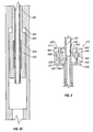
- FIGs. 5A-5C another embodiment of the vibration device 16 that provides for bi-directional longitudinal vibration is illustrated.
- the upper hammer 404 has a sleeve 472 that extends downwardly inside the housing 400.
- An inwardly protruding portion is formed on the sleeve 472.
- the lower end of the sleeve 472 is integrally attached to an impact portion 475 that has an impact surface 422.
- the impact surface 422 is designed to impact a shoulder 423 of the housing 400.
- the space between the impact surface 422 and shoulder 423 is in communication with wellbore fluid pressure through one or more side ports 424.
- the lower hammer 408 (Fig. 5C) also defines an impact shoulder 480 that is designed to impact a shoulder 482 of the housing 400.
- the space between the impact shoulder 480 and the shoulder 482 is also in communication with wellbore fluid pressure.
- a sleeve portion 481 of the lower hammer 408 extends upwardly in the housing 400 to an upper end portion 434.
- the vibration device 16 also includes a mandrel 410 and a valve mechanism 412.
- An annular piston 430 is arranged around the mandrel 410, with the upper end of the piston 430 having a flanged portion 432.
- An annular chamber 418 is defined between the lower surface of a shoulder 419 of the upper hammer 404 and the upper end 417 of the valve mechanism 412.
- Another chamber 420 is defined between the upper end portion 434 of the lower hammer 408 and the lower end 421 of the valve mechanism 412.
- the valve mechanism 412 selectively controls fluid flow from the inner bore 411 of the mandrel 410 to one of the chambers 418 and 420.
- a ball seat 436 is provided in the inner bore 411 of the mandrel 410, with the ball seat 436 adapted to receive a ball dropped from the surface.
- fluid pressure can be increased in the mandrel bore 411 to generate movement of the hammers 404 and 408 (as further described below).
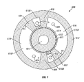
- the valve mechanism 412 is illustrated in greater detail in Fig. 6.
- the valve mechanism 412 includes a channel 442 that is in communication with the mandrel bore 411 through a port 440 in the mandrel 410.
- fluid flow in the mandrel bore 411 flows through the port 440 and channel 442 to a longitudinal channel 452 having an enlarged space 444 capable of receiving an enlarged portion 450 (forming a sealing element) of a rod 446.
- the lower end of the rod 446 is fixedly or integrally attached to the flanged portion 432 of the piston 430.
- fluid flowing into the space 444 goes upwardly through the channel 452 into the chamber 418.
- the sealing clement 450 of the rod 446 is sealably engaged with the lower surface defining the space 444 to prevent fluid flow down the channel 452.
- the seal can be created by use of an O-ring seal or coating the sealing element 450 with a suitable material. If the sealing element 450 of the rod 446 is moved upwardly to sealably engage an upper surface defining the space 444, then fluid flows downwardly through the channel 452 into the chamber 420.
- valve mechanism 412 Another part of the valve mechanism 412 includes a spring 454 that is placed in a chamber 456.
- the spring 454 is biased to ensure that in a pressure balance situation (before the drop of a ball), the valve mechanism 412 is in a position such that fluid that enters into port 440 is in communication with chamber 418, while fluid in chamber 420 is in communication with the wellbore through port 464.
- the plate 460 has a sealing element such that when the plate 460 is in contact with upper surface 417 of the valve mechanism 412, there is no fluid communication between chamber 418 and the channel 462.
- the flanged portion 432 also has a sealing element to ensure that when it is in contact with the lower surface 421 of the valve mechanism 412, there is no fluid communication between the lower chamber 420 and the channel 462.
- a rod 458 is attached to the flanged portion 432 of the piston 430.
- the upper end of the rod 458 is connected to a plate 460.
- the plate 460, rod 458, and the flanged portion 432 can be a single integral member, or alternatively, they can be separate pieces that are fixedly attached.
- the rod 458 is moveable up and down in a channel 462 defined in the valve mechanism 412.
- a ball dropped into the mandrel bore 411 lands on the ball seat 436 to create a seal.
- Fluid is then flowed down the mandrel bore 411, which enters the port 440 (Fig. 6) into the channel 442 and longitudinal channel 452 and out into the upper chamber 418.
- the increase in pressure in the chamber 418 creates a differential pressure with respect to the wellbore fluid pressure in the chamber 414, which causes the upper hammer 404 to move up with respect to the mandrel 410.
- the spring 402 is compressed.
- the sleeve 472 extending below the upper hammer 404 has the inwardly protruding portion 470.
Landscapes
- Life Sciences & Earth Sciences (AREA)
- Engineering & Computer Science (AREA)
- Geology (AREA)
- Mining & Mineral Resources (AREA)
- Geochemistry & Mineralogy (AREA)
- Fluid Mechanics (AREA)
- Environmental & Geological Engineering (AREA)
- General Life Sciences & Earth Sciences (AREA)
- Physics & Mathematics (AREA)
- Mechanical Engineering (AREA)
- Marine Sciences & Fisheries (AREA)
- Apparatuses For Generation Of Mechanical Vibrations (AREA)
- Earth Drilling (AREA)
- Manufacture, Treatment Of Glass Fibers (AREA)
- Electrophonic Musical Instruments (AREA)
- Polishing Bodies And Polishing Tools (AREA)
- Catching Or Destruction (AREA)
Claims (27)
- Appareil pour une utilisation dans un puits de forage, l'appareil comprenant :un logement (300) ayant un axe longitudinal ; etun mécanisme (304, 310, 312) comprenant des moyens d'impact (304, 312) adaptés pour se déplacer le long de l'axe longitudinal d'une manière oscillante afin de transmettre une force de va-et-vient sur le logement pour mettre le logement en vibration, caractérisé en ce que les moyens d'impact (304, 312) comprennent un premier élément d'impact (304) et un second élément d'impact (312), et le mécanisme comprend en outre une chambre de pression (314) contenant une pression élevée pour entraîner les premier et second éléments d'impact dans le logement.
- Appareil selon la revendication 1, dans lequel le premier élément d'impact (304) comprend une première surface d'actionnement (368) et le second élément d'impact (312) comprend une seconde surface d'actionnement (362), le mécanisme comprenant en outre un ensemble de soupape (310) pour communiquer la pression élevée à l'une des première et seconde surfaces d'actionnement en une fois.
- Appareil selon la revendication 2, dans lequel le premier élément d'impact (304) comprend une première chambre de réception (306) adaptée pour recevoir l'ensemble de soupape (310), l'ensemble de soupape étant adapté pour empêcher la communication de la pression élevée à la première surface d'actionnement lorsqu'il est positionné dans la première chambre de réception.
- Appareil selon la revendication 3, dans lequel l'ensemble de soupape (310) comprend un joint (326) adapté pour mettre en prise la première chambre de réception (306) afin d'isoler la première surface d'actionnement (368).
- Appareil selon la revendication 3, dans lequel l'ensemble de soupape (310) comprend un élément de soupape anti-retour (380, 386) pour relâcher la pression d'une région adjacente à la première surface d'actionnement (368).
- Appareil selon la revendication 3, dans lequel le second élément d'impact (312) comprend une seconde chambre de réception (356) adaptée pour recevoir l'ensemble de soupape (310), l'ensemble de soupape étant adapté pour empêcher la communication de la pression élevée à la seconde surface d'actionnement (362) lorsqu'il est positionné dans la seconde chambre de réception.
- Appareil selon la revendication 6, comprenant en outre un organe (308) attaché à l'ensemble de soupape (310), l'organe étant adapté pour déplacer l'ensemble de soupape entre la première chambre de réception (306) et la seconde chambre de réception (356).
- Appareil selon la revendication 6, dans lequel la pression élevée est communiquée à l'une des première et seconde surfaces d'actionnement (368, 362) lorsque l'ensemble de soupape (310) est enlevé de la chambre correspondante parmi les première et seconde chambres de réception (306, 356).
- Appareil selon la revendication 1, dans lequel le mécanisme comprend une pluralité d'éléments d'impact (404, 408) et une pluralité de ressorts (402, 406) chacun étant en prise avec un élément d'impact correspondant, les éléments d'impact étant adaptés pour se déplacer le long de l'axe longitudinal d'une manière oscillante afin de transmettre une force de va-et-vient sur le logement pour mettre le logement en vibration, et les ressorts fournissant des forces pour déplacer les éléments d'impact.
- Appareil selon la revendication 9, dans lequel le mécanisme comprend en outre une première chambre (418) contenant une pression élevée pour s'opposer à la force appliquée par le premier ressort (406).
- Appareil selon la revendication 10, dans lequel le mécanisme comprend en outre un mécanisme de soupape (412) pour éliminer la pression de la première chambre (418) afin de permettre au premier ressort (402) de déplacer le premier élément d'impact (404).
- Appareil selon la revendication 11, dans lequel le mécanisme comprend en outre une seconde chambre (420) contenant une pression élevée pour s'opposer à la force appliquée par le second ressort (406).
- Appareil selon la revendication 11, dans lequel le mécanisme de soupape (412) est adapté pour éliminer la pression de la seconde chambre (420) afin de permettre au second ressort (406) de déplacer le second élément d'impact (404).
- Appareil selon la revendication 12, comprenant en outre un conduit (411) pour délivrer la pression élevée aux première et seconde chambres (418, 420).
- Appareil selon la revendication 13, dans lequel le mécanisme de soupape (412) est adapté pour communiquer de manière sélective la pression élevée du conduit (411) à l'une des première et seconde chambres (418, 420).
- Appareil selon la revendication 1, dans lequel les éléments d'impact (304, 312 ; ou 404, 408) sont formés d'un matériau ayant un faible coefficient de dilatation thermique.
- Appareil selon la revendication 16, dans lequel les éléments d'impact (304, 312 ; ou 404, 408) sont formés d'un matériau choisi dans le groupe constitué par le carbure de tungstène, le monel K500, et l'Inconel 718.
- Appareil selon la revendication 1, dans lequel l'appareil est adapté pour faire vibrer une colonne (14), et dans lequel le mécanisme est adapté pour faire osciller les éléments d'impact (304, 312 ; ou 404, 408) à une fréquence correspondant à une fréquence de résonance de la colonne.
- Appareil selon la revendication 1, dans lequel l'appareil est adapté pour faire vibrer une colonne (14), et dans lequel le mécanisme est adapté pour faire osciller les éléments d'impact (304, 312 ; ou 404, 408) à une fréquence correspondant à la transmissibilité de la colonne dans le puits de forage.
- Appareil selon la revendication 19, dans lequel la fréquence d'oscillation est ajustable de manière dynamique pour correspondre à la transmissibilité variable de la colonne (14) dans le puits de forage.
- Appareil selon la revendication 1, dans lequel le mécanisme fournit une pression différentielle à travers chacun des éléments (304, 312) pour déplacer les éléments d'impact.
- Appareil selon la revendication 21, dans lequel la pression différentielle est variable pour faire varier une fréquence d'oscillation de chacun des éléments d'impact (304, 312).
- Appareil selon la revendication 1, dans lequel le mécanisme définit une longueur de trajet pour chacun des éléments d'impact (404, 408).
- Appareil selon la revendication 23, dans lequel la longueur de trajet est variable pour réguler une force d'impact fournie par chacun des éléments d'impact.
- Appareil selon la revendication 1, comprenant en outre un absorbeur de chocs (20A ou 20B) pour protéger les composants d'une colonne (14) des vibrations induites par le mécanisme.
- Appareil selon la revendication 1, dans lequel l'appareil est adapté pour faire vibrer une colonne de production (14) et dans lequel le fait de modifier la pression dans la chambre (314) change le spectre de fréquence de la vibration, le mécanisme (304, 310, 312) étant adapté pour fonctionner indépendamment de toute tension ou force de compression appliquée à la colonne.
- Procédé de génération de vibration dans une colonne de production, le procédé comprenant les étapes consistant à :fournir un dispositif comportant un logement, des moyens d'impact disposés dans le logement et un moyen d'entraînement agencé pour déplacer les moyens d'impact le long d'un axe longitudinal du logement d'une manière oscillante pour générer une force d'oscillation sur le logement ;caractérisé en ce que les moyens d'impact (304, 312) comprennent un premier élément d'impact (304) et un second élément d'impact (312), et le moyen d'entraînement comprend une chambre de pression (314) contenant une pression élevée pour entraîner les premier et second éléments d'impact dans le logement.
Priority Applications (1)
| Application Number | Priority Date | Filing Date | Title |
|---|---|---|---|
| EP05006070A EP1541801B1 (fr) | 2001-03-01 | 2002-02-19 | Procédé et dispositif de mise en vibration d'un outil de fond de puits |
Applications Claiming Priority (2)
| Application Number | Priority Date | Filing Date | Title |
|---|---|---|---|
| US797157 | 1985-11-12 | ||
| US09/797,157 US6571870B2 (en) | 2001-03-01 | 2001-03-01 | Method and apparatus to vibrate a downhole component |
Related Child Applications (2)
| Application Number | Title | Priority Date | Filing Date |
|---|---|---|---|
| EP05006070A Division EP1541801B1 (fr) | 2001-03-01 | 2002-02-19 | Procédé et dispositif de mise en vibration d'un outil de fond de puits |
| EP05006070.6 Division-Into | 2005-03-19 |
Publications (3)
| Publication Number | Publication Date |
|---|---|
| EP1239112A2 EP1239112A2 (fr) | 2002-09-11 |
| EP1239112A3 EP1239112A3 (fr) | 2002-10-23 |
| EP1239112B1 true EP1239112B1 (fr) | 2006-08-16 |
Family
ID=25170068
Family Applications (2)
| Application Number | Title | Priority Date | Filing Date |
|---|---|---|---|
| EP05006070A Expired - Lifetime EP1541801B1 (fr) | 2001-03-01 | 2002-02-19 | Procédé et dispositif de mise en vibration d'un outil de fond de puits |
| EP02251106A Expired - Lifetime EP1239112B1 (fr) | 2001-03-01 | 2002-02-19 | Procédé et dispositif de mise en vibration d'un outil de fond de puits |
Family Applications Before (1)
| Application Number | Title | Priority Date | Filing Date |
|---|---|---|---|
| EP05006070A Expired - Lifetime EP1541801B1 (fr) | 2001-03-01 | 2002-02-19 | Procédé et dispositif de mise en vibration d'un outil de fond de puits |
Country Status (5)
| Country | Link |
|---|---|
| US (3) | US6571870B2 (fr) |
| EP (2) | EP1541801B1 (fr) |
| CA (2) | CA2372355C (fr) |
| DK (2) | DK1239112T3 (fr) |
| NO (1) | NO322751B1 (fr) |
Families Citing this family (62)
| Publication number | Priority date | Publication date | Assignee | Title |
|---|---|---|---|---|
| GB0216074D0 (en) * | 2002-07-11 | 2002-08-21 | Weatherford Lamb | Improving collapse resistance of tubing |
| RU2235187C2 (ru) * | 2000-05-16 | 2004-08-27 | Иванников Владимир Иванович | Устройство для вибровоздействия на колонну труб в скважине (варианты) |
| US6866104B2 (en) * | 2002-01-31 | 2005-03-15 | Baker Hughes Incorporated | Drop in dart activated downhole vibration tool |
| GB2399839B (en) * | 2003-03-25 | 2007-07-11 | Weatherford Lamb | Tubing expansion |
| JP2007521428A (ja) * | 2003-06-20 | 2007-08-02 | フレックシドリル リミティド | 音響ヘッド、音響ヘッド集成体およびその使用方法 |
| US20050006146A1 (en) * | 2003-07-09 | 2005-01-13 | Mody Rustom K. | Shear strength reduction method and apparatus |
| GB0324744D0 (en) * | 2003-10-23 | 2003-11-26 | Andergauge Ltd | Running and cementing tubing |
| US7191852B2 (en) * | 2003-12-05 | 2007-03-20 | Halliburton Energy Services, Inc. | Energy accelerator |
| US7293614B2 (en) * | 2004-09-16 | 2007-11-13 | Halliburton Energy Services, Inc. | Multiple impact jar assembly and method |
| US7963324B2 (en) * | 2004-12-03 | 2011-06-21 | Schlumberger Technology Corporation | Flow control actuation |
| US7575051B2 (en) * | 2005-04-21 | 2009-08-18 | Baker Hughes Incorporated | Downhole vibratory tool |
| US8020634B2 (en) * | 2005-10-05 | 2011-09-20 | Schlumberger Technology Corporation | Method and apparatus for supporting a downhole component in a downhole drilling tool |
| US7461705B2 (en) * | 2006-05-05 | 2008-12-09 | Varco I/P, Inc. | Directional drilling control |
| US8997855B2 (en) * | 2006-09-27 | 2015-04-07 | Baker Hughes Incorporated | Reduction of expansion force via resonant vibration of a swage |
| US20080251254A1 (en) * | 2007-04-16 | 2008-10-16 | Baker Hughes Incorporated | Devices and methods for translating tubular members within a well bore |
| US7870895B2 (en) * | 2007-08-09 | 2011-01-18 | Schlumberger Technology Corporation | Packer |
| US20090120633A1 (en) * | 2007-11-13 | 2009-05-14 | Earl Webb | Method for Stimulating a Well Using Fluid Pressure Waves |
| US8113278B2 (en) | 2008-02-11 | 2012-02-14 | Hydroacoustics Inc. | System and method for enhanced oil recovery using an in-situ seismic energy generator |
| US8416196B2 (en) | 2008-03-04 | 2013-04-09 | Apple Inc. | Touch event model programming interface |
| GB2469866B (en) * | 2009-05-01 | 2013-08-28 | Dynamic Dinosaurs Bv | Method and apparatus for applying vibrations during borehold operations |
| US8162078B2 (en) | 2009-06-29 | 2012-04-24 | Ct Energy Ltd. | Vibrating downhole tool |
| US9222312B2 (en) | 2009-06-29 | 2015-12-29 | Ct Energy Ltd. | Vibrating downhole tool |
| GB0919649D0 (en) | 2009-11-10 | 2009-12-23 | Nat Oilwell Varco Lp | Downhole tractor |
| US20120160476A1 (en) | 2010-12-22 | 2012-06-28 | Bakken Gary James | Vibration tool |
| US8453727B2 (en) * | 2011-05-12 | 2013-06-04 | Baker Hughes Incorporated | Downhole rotational vibrator |
| US9109411B2 (en) | 2011-06-20 | 2015-08-18 | Schlumberger Technology Corporation | Pressure pulse driven friction reduction |
| WO2013016296A1 (fr) * | 2011-07-22 | 2013-01-31 | Scientific Drilling International, Inc. | Procédé et appareil de vibration de train de tiges pour l'amélioration de transfert de poids |
| US9382760B2 (en) * | 2011-08-23 | 2016-07-05 | Weatherford Technology Holdings, Llc | Pulsing tool |
| BR112014009085A2 (pt) | 2011-10-14 | 2017-05-09 | Precision Energy Services Inc | análise de dinâmica de coluna de perfuração usando um sensor de taxa angular |
| US9045957B2 (en) | 2011-12-08 | 2015-06-02 | Tesco Corporation | Resonant extractor system and method |
| WO2013095164A1 (fr) * | 2011-12-19 | 2013-06-27 | Flexidrill Limited | Forage à long déport |
| US9702192B2 (en) * | 2012-01-20 | 2017-07-11 | Schlumberger Technology Corporation | Method and apparatus of distributed systems for extending reach in oilfield applications |
| US9659113B2 (en) | 2012-03-15 | 2017-05-23 | Schlumberger Technology Corporation | Technique for establishing predictive reach through a deviated well |
| US9540895B2 (en) | 2012-09-10 | 2017-01-10 | Baker Hughes Incorporated | Friction reduction assembly for a downhole tubular, and method of reducing friction |
| US9500045B2 (en) | 2012-10-31 | 2016-11-22 | Canrig Drilling Technology Ltd. | Reciprocating and rotating section and methods in a drilling system |
| US20140126330A1 (en) * | 2012-11-08 | 2014-05-08 | Schlumberger Technology Corporation | Coiled tubing condition monitoring system |
| US9222316B2 (en) | 2012-12-20 | 2015-12-29 | Schlumberger Technology Corporation | Extended reach well system |
| US9470055B2 (en) | 2012-12-20 | 2016-10-18 | Schlumberger Technology Corporation | System and method for providing oscillation downhole |
| US20140216727A1 (en) * | 2013-02-05 | 2014-08-07 | Dmitry A. Kasyanov | Hydraulic drillstring sound generator |
| US9567844B2 (en) | 2013-10-10 | 2017-02-14 | Weatherford Technology Holdings, Llc | Analysis of drillstring dynamics using angular and linear motion data from multiple accelerometer pairs |
| US20150114716A1 (en) * | 2013-10-31 | 2015-04-30 | Smith International, Inc. | Vibration tool |
| US10041313B2 (en) | 2013-12-11 | 2018-08-07 | Schlumberger Technology Corporation | Method and system for extending reach in deviated wellbores using selected injection speed |
| US10301879B2 (en) | 2014-01-21 | 2019-05-28 | Halliburton Energy Services, Inc. | Variable valve axial oscillation tool |
| US9828802B2 (en) | 2014-01-27 | 2017-11-28 | Sjm Designs Pty Ltd. | Fluid pulse drilling tool |
| WO2015157318A1 (fr) * | 2014-04-07 | 2015-10-15 | Thru Tubing Solutions, Inc. | Appareil d'amélioration de vibration de fond de trou et procédé d'utilisation et d'adaptation de ce dernier |
| WO2015188155A1 (fr) | 2014-06-05 | 2015-12-10 | Toby Scott Baudoin | Vibreur de train de tiges de tuyau hydraulique pour réduire un frottement de puits de forage |
| WO2016205324A1 (fr) | 2015-06-16 | 2016-12-22 | Klx Energy Services Llc | Appareil et procédé de modification de pression de colonne de forage |
| US20180156001A1 (en) * | 2015-06-29 | 2018-06-07 | Halliburton Energy Services, Inc. | Downhole Friction Control Systems and Methods |
| CA3197974A1 (en) | 2015-08-14 | 2017-02-23 | Impulse Downhole Solutions Ltd. | Fluid pulsing assembly |
| WO2017027983A1 (fr) * | 2015-08-20 | 2017-02-23 | Impulse Downhole Solutions Ltd. | Ensemble palier de fond de trou |
| US10053926B2 (en) | 2015-11-02 | 2018-08-21 | Schlumberger Technology Corporation | Coiled tubing in extended reach wellbores |
| CA2913673C (fr) * | 2015-12-02 | 2023-03-14 | 1751303 Alberta Ltd. | Outil a vibration axiale destine a une colonne de production de fond de trou |
| CN108474237A (zh) * | 2016-01-19 | 2018-08-31 | 艾斯米恩控股有限责任公司 | 井下延伸工具方法 |
| WO2018006178A1 (fr) | 2016-07-07 | 2018-01-11 | Impulse Downhole Solutions Ltd. | Ensemble d'impulsion à écoulement traversant destiné à être utilisé dans des opérations de fond de trou |
| RU174333U1 (ru) * | 2016-10-27 | 2017-10-11 | Игорь Александрович Малыхин | Компенсатор термобарических изменений длины колонны труб с гашением продольных колебаний |
| US10787874B2 (en) * | 2017-05-18 | 2020-09-29 | Ncs Multistage Inc. | Apparatus, systems and methods for mitigating solids accumulation within the wellbore during stimulation of subterranean formations |
| WO2020146143A1 (fr) * | 2019-01-07 | 2020-07-16 | Thru Tubing Solutions, Inc. | Outil de battage et procédé d'utilisation |
| GB2606562B (en) * | 2021-05-13 | 2023-08-30 | Rotojar Innovations Ltd | Downhole drag reduction apparatus |
| AU2021401157A1 (en) * | 2020-12-16 | 2023-07-20 | Rotojar Innovations Limited | Downhole drag reduction apparatus |
| CA3202474A1 (fr) | 2020-12-16 | 2022-06-23 | Rotojar Innovations Limited | Appareil d'entrainement a va-et-vient |
| US12497890B2 (en) * | 2024-03-07 | 2025-12-16 | Weatherford Technology Holdings, Llc | Hydro-mechanical sounding device for use with acoustic telemetry system |
| US12454870B1 (en) * | 2024-08-05 | 2025-10-28 | Thru Tubing Solutions, Inc. | Advancement of a bottom hole assembly into a wellbore and workstring connection |
Family Cites Families (33)
| Publication number | Priority date | Publication date | Assignee | Title |
|---|---|---|---|---|
| US1160648A (en) * | 1914-03-09 | 1915-11-16 | Ingersoll Rand Co | Drill-steel-turning device for percussive fluid-operated drills. |
| US2146454A (en) * | 1935-06-15 | 1939-02-07 | M O Johnston | Vibrating well jar |
| DE1205024B (de) * | 1960-08-23 | 1965-11-18 | Heinz J Bienert | Rotationsvibrator fuer Erdbohrungen |
| US3361220A (en) | 1965-03-17 | 1968-01-02 | Bassinger Tool Company | Jarring or drilling mechanism |
| US3316986A (en) * | 1965-03-22 | 1967-05-02 | Exxon Production Research Co | Rotary jar-type well tool |
| US3570611A (en) * | 1968-02-09 | 1971-03-16 | Trustul Deforaj Pitesti | Device for freeing seized drill strings |
| US3770054A (en) * | 1968-12-23 | 1973-11-06 | B & W Inc | Apparatus for causing an impact force on the interior of a well pipe |
| DE2139907A1 (de) * | 1970-12-22 | 1972-07-06 | Inst Gornogo Dela Sibirskogo O | Pneumatischer Rüttler |
| US3811515A (en) * | 1973-01-15 | 1974-05-21 | A Bazhal | Percussive drilling machine |
| US3946819A (en) | 1975-01-27 | 1976-03-30 | Brown Equipment & Service Tools, Inc. | Well tool and method of use therefor |
| US4226289A (en) * | 1979-04-27 | 1980-10-07 | Webb Derrel D | Independent one-way acting hydraulic jar sections for a rotary drill string |
| US4384625A (en) * | 1980-11-28 | 1983-05-24 | Mobil Oil Corporation | Reduction of the frictional coefficient in a borehole by the use of vibration |
| US4462471A (en) | 1982-10-27 | 1984-07-31 | James Hipp | Bidirectional fluid operated vibratory jar |
| US4747466A (en) | 1983-09-06 | 1988-05-31 | Jaworski Bill L | Impact tool |
| US4573536A (en) * | 1984-11-07 | 1986-03-04 | Dailey Petroleum Services Corporation | Method and apparatus for flushing a well |
| GB8612019D0 (en) * | 1986-05-16 | 1986-06-25 | Shell Int Research | Vibrating pipe string in borehole |
| US4807709A (en) * | 1986-10-06 | 1989-02-28 | Pioneer Fishing And Rental Tools, Inc. | Fluid Powered drilling jar |
| GB8806465D0 (en) * | 1988-03-18 | 1988-04-20 | Intech Oil Tools Ltd | Flow pulsing apparatus for down-hole drilling equipment |
| US4958691A (en) | 1989-06-16 | 1990-09-25 | James Hipp | Fluid operated vibratory jar with rotating bit |
| US5156223A (en) * | 1989-06-16 | 1992-10-20 | Hipp James E | Fluid operated vibratory jar with rotating bit |
| GB9003759D0 (en) | 1990-02-20 | 1990-04-18 | Shell Int Research | Method and system for controlling vibrations in borehole equipment |
| DE4109215A1 (de) * | 1991-03-21 | 1992-09-24 | Tracto Technik | Rammbohrgeraet |
| US5273114A (en) * | 1992-06-05 | 1993-12-28 | Shell Oil Company | Gravel pack apparatus and method |
| NO301727B1 (no) * | 1993-02-10 | 1997-12-01 | Gefro Oilfield Services As | Dobbeltvirkende hydraulisk slagverktöy |
| US5957220A (en) * | 1995-10-17 | 1999-09-28 | Dresser-Rand Company | Percussion drill assembly |
| US6009948A (en) | 1996-05-28 | 2000-01-04 | Baker Hughes Incorporated | Resonance tools for use in wellbores |
| NO302586B1 (no) | 1996-06-07 | 1998-03-23 | Rf Procom As | Anordning beregnet for innkobling i en rörstreng |
| JP3712829B2 (ja) | 1997-05-15 | 2005-11-02 | 株式会社ミクロン | 空気動式バイブレータ |
| US5871277A (en) | 1997-06-04 | 1999-02-16 | Lash; Richard L. | Industrial vibrator |
| US6012521A (en) | 1998-02-09 | 2000-01-11 | Etrema Products, Inc. | Downhole pressure wave generator and method for use thereof |
| US6062324A (en) * | 1998-02-12 | 2000-05-16 | Baker Hughes Incorporated | Fluid operated vibratory oil well drilling tool |
| US6009047A (en) | 1998-07-31 | 1999-12-28 | Gte Internetworking Incorporated | Sound generation device |
| GB2343465A (en) * | 1998-10-20 | 2000-05-10 | Andergauge Ltd | Drilling method |
-
2001
- 2001-03-01 US US09/797,157 patent/US6571870B2/en not_active Expired - Fee Related
-
2002
- 2002-02-19 EP EP05006070A patent/EP1541801B1/fr not_active Expired - Lifetime
- 2002-02-19 DK DK02251106T patent/DK1239112T3/da active
- 2002-02-19 EP EP02251106A patent/EP1239112B1/fr not_active Expired - Lifetime
- 2002-02-19 DK DK05006070T patent/DK1541801T3/da active
- 2002-02-20 CA CA2372355A patent/CA2372355C/fr not_active Expired - Fee Related
- 2002-02-20 CA CA2663004A patent/CA2663004C/fr not_active Expired - Fee Related
- 2002-02-28 NO NO20020990A patent/NO322751B1/no not_active IP Right Cessation
-
2003
- 2003-03-20 US US10/393,285 patent/US6907927B2/en not_active Expired - Lifetime
-
2005
- 2005-06-20 US US11/156,951 patent/US7219726B2/en not_active Expired - Fee Related
Also Published As
| Publication number | Publication date |
|---|---|
| NO322751B1 (no) | 2006-12-04 |
| EP1239112A3 (fr) | 2002-10-23 |
| US6571870B2 (en) | 2003-06-03 |
| CA2663004A1 (fr) | 2002-09-01 |
| US20050230101A1 (en) | 2005-10-20 |
| US20040055744A1 (en) | 2004-03-25 |
| DK1541801T3 (da) | 2008-03-25 |
| CA2663004C (fr) | 2012-01-03 |
| US20020121378A1 (en) | 2002-09-05 |
| US7219726B2 (en) | 2007-05-22 |
| EP1541801A2 (fr) | 2005-06-15 |
| CA2372355C (fr) | 2011-02-15 |
| US6907927B2 (en) | 2005-06-21 |
| EP1239112A2 (fr) | 2002-09-11 |
| NO20020990L (no) | 2002-09-02 |
| NO20020990D0 (no) | 2002-02-28 |
| EP1541801B1 (fr) | 2007-11-21 |
| EP1541801A3 (fr) | 2006-01-18 |
| CA2372355A1 (fr) | 2002-09-01 |
| DK1239112T3 (da) | 2006-12-27 |
Similar Documents
| Publication | Publication Date | Title |
|---|---|---|
| EP1239112B1 (fr) | Procédé et dispositif de mise en vibration d'un outil de fond de puits | |
| US4890682A (en) | Apparatus for vibrating a pipe string in a borehole | |
| EP2235323B1 (fr) | Dispositif et procédé de perfectionnement de vitesse de pénétration à impulsions | |
| RU2159319C2 (ru) | Гидравлическое устройство для присоединения в бурильной колонне | |
| CA2686737C (fr) | Amplification hydraulique d'ecoulement pour un dispositif d'emission d'impulsions, de fracturation, et de forage (pfd) | |
| US20220049560A1 (en) | Device for generating an axial load in a drill string assembly | |
| EP2681408B1 (fr) | Générateur de force mécanique pour appareil d'excitation utilisé dans un trou de forage | |
| US20190100965A1 (en) | Down-Hole Vibrational Oscillator | |
| US7059426B2 (en) | Acoustic flow pulsing apparatus and method for drill string | |
| US20170175446A1 (en) | Force Stacking Assembly for Use with a Subterranean Excavating System | |
| US10294745B2 (en) | Reaction valve drilling jar system | |
| CA3034320C (fr) | Ensemble palier de fond de trou | |
| RU2604528C2 (ru) | Скважинное вибрационное устройство с синусоидальными колебаниями | |
| CA2874639C (fr) | Outil a impulsions axialement amplifiees | |
| EA012662B1 (ru) | Подвеска бурильной колонны | |
| EP1703073A1 (fr) | Méthode et appareil pour l'avancement de l'équipement le long d'un puits | |
| CA2354994C (fr) | Methode et appareil d'impulsions acoustiques d'ecoulement pour train de tiges | |
| WO2014041036A2 (fr) | Système de direction | |
| RU2774463C1 (ru) | Гидравлический бурильный яс двухстороннего действия | |
| RU2588059C2 (ru) | Генератор механического усилия для скважинного устройства возбуждения |
Legal Events
| Date | Code | Title | Description |
|---|---|---|---|
| PUAI | Public reference made under article 153(3) epc to a published international application that has entered the european phase |
Free format text: ORIGINAL CODE: 0009012 |
|
| PUAL | Search report despatched |
Free format text: ORIGINAL CODE: 0009013 |
|
| AK | Designated contracting states |
Kind code of ref document: A2 Designated state(s): AT BE CH CY DE DK ES FI FR GB GR IE IT LI LU MC NL PT SE TR |
|
| AX | Request for extension of the european patent |
Free format text: AL;LT;LV;MK;RO;SI |
|
| AK | Designated contracting states |
Kind code of ref document: A3 Designated state(s): AT BE CH CY DE DK ES FI FR GB GR IE IT LI LU MC NL PT SE TR |
|
| AX | Request for extension of the european patent |
Free format text: AL;LT;LV;MK;RO;SI |
|
| 17P | Request for examination filed |
Effective date: 20030422 |
|
| AKX | Designation fees paid |
Designated state(s): DK GB |
|
| REG | Reference to a national code |
Ref country code: DE Ref legal event code: 8566 |
|
| 17Q | First examination report despatched |
Effective date: 20040309 |
|
| GRAP | Despatch of communication of intention to grant a patent |
Free format text: ORIGINAL CODE: EPIDOSNIGR1 |
|
| GRAS | Grant fee paid |
Free format text: ORIGINAL CODE: EPIDOSNIGR3 |
|
| GRAA | (expected) grant |
Free format text: ORIGINAL CODE: 0009210 |
|
| AK | Designated contracting states |
Kind code of ref document: B1 Designated state(s): DK GB |
|
| REG | Reference to a national code |
Ref country code: GB Ref legal event code: FG4D |
|
| REG | Reference to a national code |
Ref country code: DK Ref legal event code: T3 |
|
| PLBE | No opposition filed within time limit |
Free format text: ORIGINAL CODE: 0009261 |
|
| STAA | Information on the status of an ep patent application or granted ep patent |
Free format text: STATUS: NO OPPOSITION FILED WITHIN TIME LIMIT |
|
| 26N | No opposition filed |
Effective date: 20070518 |
|
| PGFP | Annual fee paid to national office [announced via postgrant information from national office to epo] |
Ref country code: DK Payment date: 20150210 Year of fee payment: 14 |
|
| PGFP | Annual fee paid to national office [announced via postgrant information from national office to epo] |
Ref country code: GB Payment date: 20150218 Year of fee payment: 14 |
|
| REG | Reference to a national code |
Ref country code: DK Ref legal event code: EBP Effective date: 20160229 |
|
| GBPC | Gb: european patent ceased through non-payment of renewal fee |
Effective date: 20160219 |
|
| PG25 | Lapsed in a contracting state [announced via postgrant information from national office to epo] |
Ref country code: DK Free format text: LAPSE BECAUSE OF NON-PAYMENT OF DUE FEES Effective date: 20160229 Ref country code: GB Free format text: LAPSE BECAUSE OF NON-PAYMENT OF DUE FEES Effective date: 20160219 |
|
| P01 | Opt-out of the competence of the unified patent court (upc) registered |
Effective date: 20231208 |