EP1239173A2 - Dichtungssystem für ein Wälzlager - Google Patents
Dichtungssystem für ein Wälzlager Download PDFInfo
- Publication number
- EP1239173A2 EP1239173A2 EP02004781A EP02004781A EP1239173A2 EP 1239173 A2 EP1239173 A2 EP 1239173A2 EP 02004781 A EP02004781 A EP 02004781A EP 02004781 A EP02004781 A EP 02004781A EP 1239173 A2 EP1239173 A2 EP 1239173A2
- Authority
- EP
- European Patent Office
- Prior art keywords
- ball bearing
- seal
- shield
- fluid
- inner ring
- Prior art date
- Legal status (The legal status is an assumption and is not a legal conclusion. Google has not performed a legal analysis and makes no representation as to the accuracy of the status listed.)
- Granted
Links
- 238000007789 sealing Methods 0.000 title claims abstract description 51
- 238000005096 rolling process Methods 0.000 title description 3
- 230000002093 peripheral effect Effects 0.000 claims abstract description 9
- 239000012530 fluid Substances 0.000 abstract description 62
- 239000004519 grease Substances 0.000 abstract description 24
- 238000005086 pumping Methods 0.000 description 13
- 230000000694 effects Effects 0.000 description 6
- 230000007423 decrease Effects 0.000 description 5
- 230000003247 decreasing effect Effects 0.000 description 5
- 239000000463 material Substances 0.000 description 5
- 239000004033 plastic Substances 0.000 description 5
- 229920003023 plastic Polymers 0.000 description 5
- 238000000034 method Methods 0.000 description 4
- 229920002725 thermoplastic elastomer Polymers 0.000 description 4
- 239000000428 dust Substances 0.000 description 3
- 230000009545 invasion Effects 0.000 description 3
- 229920003051 synthetic elastomer Polymers 0.000 description 3
- 239000005061 synthetic rubber Substances 0.000 description 3
- XEEYBQQBJWHFJM-UHFFFAOYSA-N Iron Chemical compound [Fe] XEEYBQQBJWHFJM-UHFFFAOYSA-N 0.000 description 2
- 239000004952 Polyamide Substances 0.000 description 2
- 229920001971 elastomer Polymers 0.000 description 2
- 239000000806 elastomer Substances 0.000 description 2
- 230000001747 exhibiting effect Effects 0.000 description 2
- 230000033001 locomotion Effects 0.000 description 2
- 239000002184 metal Substances 0.000 description 2
- 229910052751 metal Inorganic materials 0.000 description 2
- 150000002739 metals Chemical class 0.000 description 2
- 238000000465 moulding Methods 0.000 description 2
- 238000005192 partition Methods 0.000 description 2
- 229920002647 polyamide Polymers 0.000 description 2
- 238000004904 shortening Methods 0.000 description 2
- 239000010935 stainless steel Substances 0.000 description 2
- 229910001220 stainless steel Inorganic materials 0.000 description 2
- 229920005992 thermoplastic resin Polymers 0.000 description 2
- 229910000838 Al alloy Inorganic materials 0.000 description 1
- 229910000881 Cu alloy Inorganic materials 0.000 description 1
- 229920000181 Ethylene propylene rubber Polymers 0.000 description 1
- YCKRFDGAMUMZLT-UHFFFAOYSA-N Fluorine atom Chemical compound [F] YCKRFDGAMUMZLT-UHFFFAOYSA-N 0.000 description 1
- 229930182556 Polyacetal Natural products 0.000 description 1
- 239000004793 Polystyrene Substances 0.000 description 1
- 229910000639 Spring steel Inorganic materials 0.000 description 1
- 229910000831 Steel Inorganic materials 0.000 description 1
- NIXOWILDQLNWCW-UHFFFAOYSA-N acrylic acid group Chemical group C(C=C)(=O)O NIXOWILDQLNWCW-UHFFFAOYSA-N 0.000 description 1
- 239000000919 ceramic Substances 0.000 description 1
- 239000010960 cold rolled steel Substances 0.000 description 1
- 238000000748 compression moulding Methods 0.000 description 1
- 239000000470 constituent Substances 0.000 description 1
- 238000001816 cooling Methods 0.000 description 1
- 239000011162 core material Substances 0.000 description 1
- 239000011737 fluorine Substances 0.000 description 1
- 229910052731 fluorine Inorganic materials 0.000 description 1
- 238000001746 injection moulding Methods 0.000 description 1
- 229910052742 iron Inorganic materials 0.000 description 1
- 239000007769 metal material Substances 0.000 description 1
- 238000012986 modification Methods 0.000 description 1
- 230000004048 modification Effects 0.000 description 1
- 150000002825 nitriles Chemical class 0.000 description 1
- 229920005668 polycarbonate resin Polymers 0.000 description 1
- 239000004431 polycarbonate resin Substances 0.000 description 1
- 229920000728 polyester Polymers 0.000 description 1
- -1 polyethylene terephthalate Polymers 0.000 description 1
- 229920000139 polyethylene terephthalate Polymers 0.000 description 1
- 239000005020 polyethylene terephthalate Substances 0.000 description 1
- 229920001721 polyimide Polymers 0.000 description 1
- 239000009719 polyimide resin Substances 0.000 description 1
- 229920000098 polyolefin Polymers 0.000 description 1
- 229920006324 polyoxymethylene Polymers 0.000 description 1
- 229920001296 polysiloxane Polymers 0.000 description 1
- 229920002223 polystyrene Polymers 0.000 description 1
- 229920002635 polyurethane Polymers 0.000 description 1
- 239000004814 polyurethane Substances 0.000 description 1
- 229920000915 polyvinyl chloride Polymers 0.000 description 1
- 239000004800 polyvinyl chloride Substances 0.000 description 1
- 230000003014 reinforcing effect Effects 0.000 description 1
- 239000005060 rubber Substances 0.000 description 1
- 239000010959 steel Substances 0.000 description 1
- KKEYFWRCBNTPAC-UHFFFAOYSA-L terephthalate(2-) Chemical compound [O-]C(=O)C1=CC=C(C([O-])=O)C=C1 KKEYFWRCBNTPAC-UHFFFAOYSA-L 0.000 description 1
- 238000001721 transfer moulding Methods 0.000 description 1
Images



Classifications
-
- F—MECHANICAL ENGINEERING; LIGHTING; HEATING; WEAPONS; BLASTING
- F16—ENGINEERING ELEMENTS AND UNITS; GENERAL MEASURES FOR PRODUCING AND MAINTAINING EFFECTIVE FUNCTIONING OF MACHINES OR INSTALLATIONS; THERMAL INSULATION IN GENERAL
- F16C—SHAFTS; FLEXIBLE SHAFTS; ELEMENTS OR CRANKSHAFT MECHANISMS; ROTARY BODIES OTHER THAN GEARING ELEMENTS; BEARINGS
- F16C33/00—Parts of bearings; Special methods for making bearings or parts thereof
- F16C33/72—Sealings
- F16C33/76—Sealings of ball or roller bearings
- F16C33/78—Sealings of ball or roller bearings with a diaphragm, disc, or ring, with or without resilient members
- F16C33/784—Sealings of ball or roller bearings with a diaphragm, disc, or ring, with or without resilient members mounted to a groove in the inner surface of the outer race and extending toward the inner race
- F16C33/7843—Sealings of ball or roller bearings with a diaphragm, disc, or ring, with or without resilient members mounted to a groove in the inner surface of the outer race and extending toward the inner race with a single annular sealing disc
- F16C33/7846—Sealings of ball or roller bearings with a diaphragm, disc, or ring, with or without resilient members mounted to a groove in the inner surface of the outer race and extending toward the inner race with a single annular sealing disc with a gap between the annular disc and the inner race
-
- F—MECHANICAL ENGINEERING; LIGHTING; HEATING; WEAPONS; BLASTING
- F16—ENGINEERING ELEMENTS AND UNITS; GENERAL MEASURES FOR PRODUCING AND MAINTAINING EFFECTIVE FUNCTIONING OF MACHINES OR INSTALLATIONS; THERMAL INSULATION IN GENERAL
- F16C—SHAFTS; FLEXIBLE SHAFTS; ELEMENTS OR CRANKSHAFT MECHANISMS; ROTARY BODIES OTHER THAN GEARING ELEMENTS; BEARINGS
- F16C19/00—Bearings with rolling contact, for exclusively rotary movement
- F16C19/02—Bearings with rolling contact, for exclusively rotary movement with bearing balls essentially of the same size in one or more circular rows
- F16C19/04—Bearings with rolling contact, for exclusively rotary movement with bearing balls essentially of the same size in one or more circular rows for radial load mainly
- F16C19/06—Bearings with rolling contact, for exclusively rotary movement with bearing balls essentially of the same size in one or more circular rows for radial load mainly with a single row or balls
Definitions
- the present invention relates to a sealing structure of a ball bearing and more particularly to a sealing structure of a ball bearing wherein a seal or a shield is provided on at least one side of the ball bearing to further improve the sealing performance.
- a shield ball bearing wherein a shield formed by a stainless steel plate is provided on a side of the bearing and a seal ball bearing wherein a seal formed of such a material as synthetic rubber or thermoplastic resin or elastomer is provided on a side of the bearing.
- the invasion of foreign matter or dust from the exterior to the interior of the bearing is prevented, and in the case where grease is sealed in the interior of the bearing, leakage of the grease to the exterior is prevented.
- the sealing performance is enhanced to a greater extent than that in the shield ball bearing, and the invasion of foreign matter or dust from the exterior into the bearing and the leakage of grease sealed in the interior of the bearing are prevented more effectively.
- such a shield or seal is provided fixedly on an outer ring of a ball bearing.
- a singe shield (seal) type with the shield (seal) provided on only one side of the bearing and a double shield (seal) type with the shield (seal) provided on both sides of the bearing are available.
- the shield is provided on an outer ring spacing a slight gap against an inner ring so as not to contact the inner ring, while as to the seal there are known a non contact type wherein the seal is provided so as not to contact the inner ring and a contact type wherein the seal is provided in contact with the inner ring.
- a high-pressure air present in a fan driving motor receptacle chamber 012 which also serves as a discharge chamber may flow reverse toward a fan receptacle chamber 011 through a ball bearing 014 mounted to a wall 013 which partitions between the fan receptacle chamber 011 and the motor receptacle chamber 012.
- a streamline A represents a normal air flow
- a streamline B represents the above reversing air flow toward the fan receptacle chamber 011.
- grease present in a gear receptacle chamber 024 may leak into a motor-fan receptacle chamber 023 accommodating both a drive motor 021 and a motor cooling fan 022, through a ball bearing 026 mounted to a wall which is a part of a wall of a gear box 025 defining the gear receptacle chamber 024 and which partitions between the motor-fan receptacle chamber 023 and the gear receptacle chamber 024.
- the ball bearing In such various cases as referred to above, it has come to be expected more and more keenly for the ball bearing to function as a component capable of preventing flowing or leakage of air or grease through the ball bearing between spaces defined on both sides of the ball bearing mounted in the bearing portion concerned or as a component capable of preventing grease sealed in the ball bearing itself from leaking out to a lower-pressure space located on one side of the ball bearing.
- the present invention has been accomplished for solving the above-mentioned problems involved in the conventional ball bearing sealing structure and it is an object of the present invention to provide a ball bearing sealing structure capable of effectively preventing, with a simple structure, flowing or leakage of fluid through the ball bearing between spaces formed on both sides of the ball bearing mounted in a bearing portion, also capable of effectively preventing grease sealed in the ball bearing itself from leaking into a lower-pressure space formed on one side of the ball bearing, and thus exhibiting a further improved sealing performance.
- a sealing structure of a ball bearing wherein a seal or a shield is provided on at least one side of the ball bearing and the ball bearing is used under rotation of an outer ring, characterized in that a large number of blade projections are formed radially on an outer surface of the seal or the shield provided on one side of the ball bearing.
- the seal or the shield upon rotation of the outer ring, rotates together with the outer ring, and the blade projections formed on the outer surface of the seal or the shield cause fluid which is in contact with the said outer surface to be scattered radially outward from the inside by virtue of centrifugal force in an apparatus or equipment to which the ball bearing is applied.
- the blade projections exhibit a pumping action for a fluid which is in contact with the outer surface of the seal or the shield.
- the ball bearing is disposed so that the side (one side of the ball bearing) with the blade projections-formed seal or shield provided thereon faces the space higher in pressure out of the spaces formed on both sides of the ball bearing, whereby fluid present near the inner ring is scattered radially outward in the space higher in pressure, resulting in that the pressure in this region drops and a pressure difference between fluids present near the inner ring in both spaces partitioned by the ball bearing decreases or reverses.
- a sealing structure of a ball bearing wherein a seal or a shield is provided on at least one side of the ball bearing and the ball bearing is used under rotation of an inner ring, characterized in that a large number of blade projections are formed radially on an outer surface of the seal or the shield provided on one side of the ball bearing, and an annular plate is mounted on a shaft with the inner ring fitted thereon at a position relatively dose to the blade projections.
- the annular plate rotates together with the inner ring through the shaft.
- fluid which is present in the region sandwiched between the annular plate and the ball bearing is pulled by virtue of a viscous force and is made to rotate together with the annular plate. Therefore, the fluid present in the said region and the blade projections formed on the outer surface of the seal or the shield perform a relative rotational motion and the blade projections cause the fluid present in this region and in contact with the said outer surface to be scattered radially outwards from the inside by virtue of a centrifugal force.
- the blade projections exhibit a pumping action for the fluid which is in contact with the outer surface of the seal or the shield.
- the ball bearing is disposed so that the side (one side of the ball bearing) with the blade projections-formed seal or shield provided thereon faces the space higher in pressure out of the spaces formed on both sides of the ball bearing, whereby the fluid present around the inner ring is scattered radially outwards in the higher-pressure space, with the result that the pressure of the fluid in this region (the region near the inner ring and sandwiched between the annular plate and the ball bearing) drops and the difference in pressure between fluids present near the inner ring in both spaces partitioned by the ball bearing decreases or reverses.
- a sealing structure of a ball bearing wherein a plurality of through holes are formed circumferentially on or near an inner peripheral edge of the annular plate.
- a plurality of balls 4 are inserted into and held between a raceway groove formed on the outer peripheral surface of an inner ring 2 and a raceway groove formed on the inner peripheral surface of an outer ring 3 by means of a retainer 5.
- seals 6 which are formed of a rubber material and which are fitted in the outer ring 3. Ends of the seals 6 are not in contact with the inner ring 2, with a slight gap formed therebetween.
- the ball bearing 1 has the structure and form of a double seal/non-contact seal ball bearing.
- a core material 7 is fitted in an inner surface of each seal 6 by molding.
- the ball bearing 1 is used so that the outer ring rotates. Therefore, in a device or equipment to which the ball bearing 1 is applied, the outer ring 3 is fitted from the inside into a circular hole formed in a wall 8 of a component which belongs to a rotating side, while the inner ring 2 is fitted on a fixed shaft 9 from the outside.
- the righthand space S in Fig. 1 is held at a higher pressure than the left-hand space T and, for example, can be a space for the passage of discharge fluid (say, discharge air) in a fluid machine or can be a grease storing space within a gear box of a motor-driven tool.
- discharge fluid say, discharge air
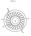
- blade projections 10 are formed radially on the outer surface of the seal. It is preferable that the blade projections 10 be formed by molding integrally with the body portion of the seal 6.
- the blade projections 10 are designed to have optimum length, thickness, height and shape so that they can exert an effective pumping action on the fluid in the space S, as will be described later.
- the blade projections 10 are curved, they may be formed in a rectilinear shape.
- the seals 6 fitted in the outer ring 3 on both sides of the ball bearing 1 hold grease sealed in the interior of the ball bearing so as to prevent leakage of the grease to the exterior and protect the ball bearing so as not to permit the invasion of foreign matter and dust from the exterior to the interior of the bearing.
- the sealing function it is possible to let the sealing function be also exhibited partially so as to prevent flowing or leakage of fluid from the higher-pressure space S to the lower-pressure space T.
- the seals 6 rotate together with the outer ring, and the blade projections 10 formed on the outer surface of the high pressure-side seal 6 causes fluid (e.g., air or grease) which is in contact with the said outer surface to be scattered radially outwards from the inside (see a streamline C in Fig. 1) by virtue of a centrifugal force in an apparatus or equipment to which the ball bearing 1 is applied. That is, the blade projections 10 exhibit a pumping action for the fluid which is in contact with the outer surface of the high pressure-side seal 6.
- fluid e.g., air or grease
- the "fluid present near the inner ring 2" mainly indicates the fluid present in a side region of the inner ring 2 which includes a portion facing the gap formed between the end of each seal 6 and the outer peripheral surface of the inner ring 2 and on which the pumping action of the blade projections 10 is exerted. interior of the bearing. Where there is a pressure difference between both spaces S and T formed on both sides of the ball bearing 1, it is possible to let the sealing function be also exhibited partially so as to prevent flowing or leakage of fluid from the higher-pressure space S to the lower-pressure space T.
- the seals 6 rotate together with the outer ring, and the blade projections 10 formed on the outer surface of the high pressure-side seal 6 causes fluid (e.g., air or grease) which is in contact with the said outer surface to be scattered radially outwards from the inside (see a streamline C in Fig. 1) by virtue of a centrifugal force in an apparatus or equipment to which the ball bearing 1 is applied. That is, the blade projections 10 exhibit a pumping action for the fluid which is in contact with the outer surface of the high pressure-side seal 6.
- fluid e.g., air or grease
- the "fluid present near the inner ring 2" mainly indicates the fluid present in a side region of the inner ring 2 which includes a portion facing the gap formed between the end of each seal 6 and the outer peripheral surface of the inner ring 2 and on which the pumping action of the blade projections 10 is exerted.
- Flowing or leakage of fluid from the higher-pressure space S to the lower-pressure space T through the ball bearing 1 occurs mainly through the gap between the inner and outer rings 2, 3 of the ball bearing1, but can also occur through a slight gap formed between the inner ring 2 and the fixed shaft 9.
- the seal 6 may be substituted by a shield and such blade projections 10 as described above may be formed on an outer surface of the shield. Also in this case the ball bearing 1 can exhibit a high sealing performance.
- each seal 6 or shield and how to form it are not specially limited. There may be adopted any of the following known materials (metals, plastics, thermoplastic elastomers, and synthetic rubbers) and known forming methods.
- thermoplastic resins as polyamide, polyacetal, polybutyrene terephthalate, polyethylene terephthalate, polycarbonate, and polyimide resins.
- thermoplastic elastomers examples include polyamide, polyester, polyurethane, polyolefine, polystyrene, and polyvinyl chloride elastomers.
- synthetic rubbers are mentioned nitrile, acrylic, silicone, fluorine-containing, and ethylene-propylene rubbers.
- plastic working methods such as press working.
- thermoplastic elastomer examples of the method for forming a seal or a member as a constituent of the seal using a plastic or a thermoplastic elastomer there are mentioned injection molding, compression molding, and transfer molding.
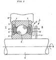
- Fig. 3 is a partial, vertical sectional view of a ball bearing sealing structure according to the second embodiment, in which the same portions as in the ball bearing sealing structure of the first embodiment are identified by the same reference numerals as in the first embodiment.
- the sealing structure of the ball bearing 1 in this second embodiment is different in structure from the ball bearing sealing structure of the first embodiment only in that an annular plate 11 is mounted on the shaft (rotary shaft) 9 with the inner ring 2 fitted thereon, at a position relatively close to the blade projections 10.
- an annular plate 11 is mounted on the shaft (rotary shaft) 9 with the inner ring 2 fitted thereon, at a position relatively close to the blade projections 10.
- a difference is recognized only in that the ball bearing 1 in this second embodiment is used under rotation of the inner ring 2.
- the annular plate 11 rotates together with the inner ring 2 through the rotary shaft 9. Then, in a device or equipment to which the ball bearing 1 is applied, the fluid present in the region sandwiched between the annular plate 11 and the ball bearing 1 is pulled by virtue of a viscous force and is made to rotate together with the annular plate 11, so that the fluid present in this region and the blade projections 10 formed on the outer surface of the high pressure-side seal 6 perform a relative rotational motion, and the blade projections 10 cause the fluid (air or grease) which is in contact with the outer surface of the high pressure-side seal 6 in this region to be scattered radially outwards from the inside by virtue of a centrifugal force.
- the seal 6 may be substituted by a shield, and even if such blade projections 10 as described above are formed on the outer surface of the shield, the ball bearing 1 can exhibit a high sealing performance to the same extent as above.
- Fig. 4 is a front view showing a portion of an annular plate used in a ball bearing sealing structure according to this third embodiment, in which the same portions as in the ball bearing sealing structure of the previous second embodiment are identified by the same reference numerals as in the second embodiment.
- a plurality of through holes 12 are formed circumferentially in the vicinity of an inner peripheral edge of the annular plate 11 used therein.
- the plural through holes 12 may be formed by cutting off the inner peripheral edge of the annular plate 11 each in a semicircular shape.
- the size of each through hole 12 is set to an appropriate size in relation to the pumping action of the blade projections 10.
- the third embodiment is constructed as above, it is not necessary to let fluid reciprocate within the narrow region sandwiched between the annular plate 11 and the ball bearing 1 (see the streamline D in Fig. 3), and a high-pressure fluid is constantly replenished under reduced pressure into a fluid pressure dropping portion in the region near the inner ring 2 included in the said narrow region through the plural through holes 12 from the higher-pressure space S located on the side opposite to the ball bearing 1 with respect to the annular plate 11, whereby it is possible to establish a circulation path free of any difficulty in flowing for the fluid which undergoes the pumping action. In this way the pumping action of the blade projections 10 can be allowed to proceed smoothly and the foregoing effects attained by the second embodiment can be further promoted.
- the ball bearings 1 described in the above first to third embodiments have the structure and form of a double-seal/non-contact type seal ball bearing or a double-shield/non-contact type shield ball bearing, no limitation is made thereto. They may be of various other structures and forms, including double-seal/contact type, single-seal/non-contact type, and single-seal/contact type seal ball bearings, double-shield/ contact type, single-shield/non-contact type, and single-shield/contact type shield ball bearings, seal ball bearings having a seal of a double structure, and shield ball bearings having a shield of a double structure.
Landscapes
- Engineering & Computer Science (AREA)
- General Engineering & Computer Science (AREA)
- Mechanical Engineering (AREA)
- Sealing Of Bearings (AREA)
- Rolling Contact Bearings (AREA)
Applications Claiming Priority (2)
| Application Number | Priority Date | Filing Date | Title |
|---|---|---|---|
| JP2001059751 | 2001-03-05 | ||
| JP2001059751A JP2002266880A (ja) | 2001-03-05 | 2001-03-05 | 玉軸受のシール構造 |
Publications (3)
| Publication Number | Publication Date |
|---|---|
| EP1239173A2 true EP1239173A2 (de) | 2002-09-11 |
| EP1239173A3 EP1239173A3 (de) | 2004-09-15 |
| EP1239173B1 EP1239173B1 (de) | 2006-08-09 |
Family
ID=18919269
Family Applications (1)
| Application Number | Title | Priority Date | Filing Date |
|---|---|---|---|
| EP02004781A Expired - Lifetime EP1239173B1 (de) | 2001-03-05 | 2002-03-01 | Dichtungssystem für ein Wälzlager |
Country Status (5)
| Country | Link |
|---|---|
| US (1) | US6715765B2 (de) |
| EP (1) | EP1239173B1 (de) |
| JP (1) | JP2002266880A (de) |
| AT (1) | ATE335937T1 (de) |
| DE (1) | DE60213694T2 (de) |
Cited By (11)
| Publication number | Priority date | Publication date | Assignee | Title |
|---|---|---|---|---|
| EP1493935A1 (de) * | 2003-06-30 | 2005-01-05 | Koyo Seiko Co., Ltd. | Wälzlager |
| EP1450058A3 (de) * | 2003-02-18 | 2005-12-14 | Koyo Seiko Co., Ltd. | Wälzlager mit Laufring aus Keramik |
| DE10324849B4 (de) * | 2003-06-02 | 2005-12-22 | Minebea Co., Ltd. | Elektromotor mit einer Wellendichtung zur Abdichtung einer Motorwelle des Elektromotors |
| EP1719927A4 (de) * | 2004-02-18 | 2007-09-26 | Jtekt Corp | Wälzlager für auflader |
| EP1903231A3 (de) * | 2006-09-20 | 2009-04-29 | HILTI Aktiengesellschaft | Wellenlagerdichtung |
| WO2009142574A1 (en) * | 2008-05-23 | 2009-11-26 | Scania Cv Ab | Wheel suspension device |
| EP2180214A1 (de) * | 2008-10-24 | 2010-04-28 | Makita Corporation | Dichtungsvorrichtung für Getriebegehäuse |
| WO2010112380A1 (de) * | 2009-04-03 | 2010-10-07 | Schaeffler Technologies Gmbh & Co. Kg | Ausrücklager mit konkaver dichtlippe |
| WO2012171719A1 (de) * | 2011-06-17 | 2012-12-20 | Schaeffler Technologies AG & Co. KG | Lüftkühlung für wälzlager |
| GB2529654A (en) * | 2014-08-28 | 2016-03-02 | Skf Ab | Bearing |
| GB2602029A (en) * | 2020-12-15 | 2022-06-22 | Edwards S R O | A pump and a bearing assembly for a pump |
Families Citing this family (19)
| Publication number | Priority date | Publication date | Assignee | Title |
|---|---|---|---|---|
| DE102004040622A1 (de) * | 2004-08-21 | 2006-02-23 | Voith Paper Patent Gmbh | Rakelvorrichtung |
| JP4639868B2 (ja) * | 2005-03-11 | 2011-02-23 | 日本精工株式会社 | シールリング付転がり軸受 |
| EP1707856A1 (de) * | 2005-04-01 | 2006-10-04 | Cross Manufacturing Company (1938) Limited | Bürstendichtungen |
| JP4456062B2 (ja) * | 2005-12-16 | 2010-04-28 | 株式会社酉島製作所 | 流体機械のシール装置 |
| JP2007192356A (ja) * | 2006-01-20 | 2007-08-02 | Nsk Ltd | 転がり軸受用密封装置 |
| GB2440544A (en) * | 2006-08-02 | 2008-02-06 | Rolls Royce Plc | Bearing discharge flow control arrangement |
| EP2136212A4 (de) * | 2007-03-28 | 2012-07-25 | Ntn Toyo Bearing Co Ltd | Rotationssensor |
| JP5063209B2 (ja) * | 2007-06-20 | 2012-10-31 | Ntn株式会社 | 回転検出センサ・固定部材取付体 |
| DE102008036623A1 (de) * | 2008-08-06 | 2010-02-11 | Oerlikon Leybold Vacuum Gmbh | Verwendung eines Wälzlagers zur Lagerung rotierender Bauteile in Vakuumeinirchtungen sowie Vakuumeinrichtung |
| US20110127995A1 (en) * | 2008-08-11 | 2011-06-02 | Kentarou Nishikawa | Rotation sensor |
| US20100201072A1 (en) * | 2009-02-06 | 2010-08-12 | Wians Jeffrey A | One piece shaft seal apparatus and method |
| US8297949B1 (en) * | 2009-02-17 | 2012-10-30 | Mancl Scott C | Bearing seal for a wet vacuum motor |
| CN102371573A (zh) * | 2010-08-10 | 2012-03-14 | 南京德朔实业有限公司 | 电动工具 |
| JP2013002687A (ja) * | 2011-06-14 | 2013-01-07 | Sumitomo Heavy Ind Ltd | 蓄冷器式冷凍機 |
| US9377054B2 (en) | 2014-05-19 | 2016-06-28 | Seagate Technology Llc | Fluid seal for a rotating assembly |
| US10156240B2 (en) | 2016-06-16 | 2018-12-18 | Scott C. Mancl | Motor-driven fan with trapped adhesive for minimizing vibration |
| CN106704381A (zh) * | 2016-12-15 | 2017-05-24 | 碎得机械(北京)有限公司 | 一种剖分式深沟球轴承 |
| JP7266992B2 (ja) * | 2018-11-12 | 2023-05-01 | Nok株式会社 | 気流発生構造体及び密封構造 |
| US12506380B2 (en) | 2023-06-24 | 2025-12-23 | Scott C. Mancl | Bearing seal for motors |
Family Cites Families (23)
| Publication number | Priority date | Publication date | Assignee | Title |
|---|---|---|---|---|
| US4091988A (en) * | 1976-06-21 | 1978-05-30 | Albert G. Bodine | Centrifugal trap for solid particles |
| US4181312A (en) * | 1978-05-11 | 1980-01-01 | Douglas Frederick | Slinger device |
| JPS55113177A (en) * | 1979-02-23 | 1980-09-01 | Nec Corp | Air ventilating mechanism of magnetic disk unit |
| US4223749A (en) * | 1979-03-15 | 1980-09-23 | Bodine Albert G | Rotary earth boring drill bit with centrifugal foreign particle barrier device |
| DE2930462C2 (de) * | 1979-07-27 | 1983-11-03 | Fa. Carl Freudenberg, 6940 Weinheim | Schlammdichtung |
| JPS56108021A (en) * | 1980-01-31 | 1981-08-27 | Osaka Cement Kk | Utilizing method of bamboo as industrial fuel |
| US4446933A (en) * | 1982-03-29 | 1984-05-08 | Bodine Albert G | Rotary earth boring drill bit with centrifugal lubrication system |
| US4808012A (en) * | 1987-03-23 | 1989-02-28 | The Timken Company | Flap seal for anti-friction bearings |
| JPH01115070U (de) * | 1988-01-29 | 1989-08-02 | ||
| IT1256785B (it) * | 1992-01-28 | 1995-12-15 | Skf Ind Spa | Complesso di tenuta con un dispositivo sensore a bordo, per un cuscinetto di rotolamento. |
| DE4215905A1 (de) * | 1992-05-14 | 1993-11-18 | Skf Gmbh | Dichtung für Lager, insbesondere Wälzlager |
| US5242229A (en) * | 1992-11-25 | 1993-09-07 | The Torrington Company | Sealing structure for standardized bearing ring |
| DE4329398A1 (de) * | 1993-01-13 | 1994-07-14 | Ford Werke Ag | Wälzlager |
| US5560715A (en) * | 1995-04-26 | 1996-10-01 | The Torrington Company | Rolling element bearing with shield |
| JP2917115B2 (ja) * | 1995-11-20 | 1999-07-12 | ミネベア株式会社 | 転がり軸受 |
| US5947611A (en) * | 1996-01-22 | 1999-09-07 | Nsk Ltd. | Rolling bearing unit with tone wheel |
| JP3740219B2 (ja) * | 1996-07-05 | 2006-02-01 | 光洋精工株式会社 | 転がり軸受の密封装置 |
| GB9615941D0 (en) * | 1996-07-30 | 1996-09-11 | Timken Co | Combined bearing and sensor assembly |
| US5979903A (en) * | 1997-12-04 | 1999-11-09 | Sanford Acquisition Company | Translucent slinger with centrifugal seal |
| JPH11230179A (ja) * | 1998-02-19 | 1999-08-27 | Nippon Seiko Kk | 転がり軸受 |
| FR2781850B1 (fr) * | 1998-07-29 | 2000-09-08 | Roulements Soc Nouvelle | Roulement pour chaine d'etirage |
| JP2001263359A (ja) * | 2000-03-16 | 2001-09-26 | Fuji Heavy Ind Ltd | 軸受けのシール装置 |
| JP2002227859A (ja) * | 2001-01-31 | 2002-08-14 | Koyo Seiko Co Ltd | 車軸用軸受の密封装置 |
-
2001
- 2001-03-05 JP JP2001059751A patent/JP2002266880A/ja active Pending
-
2002
- 2002-03-01 AT AT02004781T patent/ATE335937T1/de not_active IP Right Cessation
- 2002-03-01 EP EP02004781A patent/EP1239173B1/de not_active Expired - Lifetime
- 2002-03-01 DE DE60213694T patent/DE60213694T2/de not_active Expired - Lifetime
- 2002-03-04 US US10/087,219 patent/US6715765B2/en not_active Expired - Fee Related
Non-Patent Citations (1)
| Title |
|---|
| None |
Cited By (15)
| Publication number | Priority date | Publication date | Assignee | Title |
|---|---|---|---|---|
| EP1450058A3 (de) * | 2003-02-18 | 2005-12-14 | Koyo Seiko Co., Ltd. | Wälzlager mit Laufring aus Keramik |
| US7431511B2 (en) | 2003-02-18 | 2008-10-07 | Koyo Seiko Co., Ltd. | Rolling bearing |
| DE10324849B4 (de) * | 2003-06-02 | 2005-12-22 | Minebea Co., Ltd. | Elektromotor mit einer Wellendichtung zur Abdichtung einer Motorwelle des Elektromotors |
| EP1493935A1 (de) * | 2003-06-30 | 2005-01-05 | Koyo Seiko Co., Ltd. | Wälzlager |
| US7237961B2 (en) | 2003-06-30 | 2007-07-03 | Koyo Seiko Co., Ltd. | Rolling bearing |
| EP1719927A4 (de) * | 2004-02-18 | 2007-09-26 | Jtekt Corp | Wälzlager für auflader |
| EP1903231A3 (de) * | 2006-09-20 | 2009-04-29 | HILTI Aktiengesellschaft | Wellenlagerdichtung |
| WO2009142574A1 (en) * | 2008-05-23 | 2009-11-26 | Scania Cv Ab | Wheel suspension device |
| EP2180214A1 (de) * | 2008-10-24 | 2010-04-28 | Makita Corporation | Dichtungsvorrichtung für Getriebegehäuse |
| CN101725702B (zh) * | 2008-10-24 | 2015-04-08 | 株式会社牧田 | 齿轮箱的密封构造 |
| WO2010112380A1 (de) * | 2009-04-03 | 2010-10-07 | Schaeffler Technologies Gmbh & Co. Kg | Ausrücklager mit konkaver dichtlippe |
| WO2012171719A1 (de) * | 2011-06-17 | 2012-12-20 | Schaeffler Technologies AG & Co. KG | Lüftkühlung für wälzlager |
| GB2529654A (en) * | 2014-08-28 | 2016-03-02 | Skf Ab | Bearing |
| US9638253B2 (en) | 2014-08-28 | 2017-05-02 | Aktiebolaget Skf | Bearing |
| GB2602029A (en) * | 2020-12-15 | 2022-06-22 | Edwards S R O | A pump and a bearing assembly for a pump |
Also Published As
| Publication number | Publication date |
|---|---|
| ATE335937T1 (de) | 2006-09-15 |
| EP1239173B1 (de) | 2006-08-09 |
| JP2002266880A (ja) | 2002-09-18 |
| US6715765B2 (en) | 2004-04-06 |
| US20020130470A1 (en) | 2002-09-19 |
| EP1239173A3 (de) | 2004-09-15 |
| DE60213694D1 (de) | 2006-09-21 |
| DE60213694T2 (de) | 2007-02-22 |
Similar Documents
| Publication | Publication Date | Title |
|---|---|---|
| EP1239173B1 (de) | Dichtungssystem für ein Wälzlager | |
| US6336638B1 (en) | Radial shaft seal | |
| US7201685B2 (en) | Pulley unit | |
| US20030189294A1 (en) | Sliding element | |
| US8647085B2 (en) | Scroll fluid machine having a communication passage between an inner periphery of lip seal and an outer periphery of drive shaft or ring | |
| US20080284110A1 (en) | Prelubricated Multi-Lipped Radial Shaft Seal With Large Radial Offset Accommodation | |
| US10794428B2 (en) | Sealing device and hub bearing | |
| US4655617A (en) | Sealed rolling bearing with a flow reducing grease passage | |
| MX2007000655A (es) | Dispositivo de sello de cara de extremo tipo labio. | |
| MX2013002912A (es) | Ensamble de sellado de fluido. | |
| JPWO2016158718A1 (ja) | 密封装置 | |
| US10260635B2 (en) | Sealing device | |
| CN100412398C (zh) | 流体轴承模组 | |
| WO2020009005A1 (ja) | 密封装置 | |
| JP6174288B1 (ja) | 密封装置 | |
| JPS62210282A (ja) | オイルフリ−流体機械の軸封装置 | |
| US6659747B2 (en) | Shaft seal structure of vacuum pumps | |
| US11692591B2 (en) | Sealing device for a bearing unit | |
| CN103562555A (zh) | 带有液体防渗透装置的用于吸取气体射流的离心电泵 | |
| JPS6340650Y2 (de) | ||
| JPH0673545U (ja) | オイルシール | |
| KR102635743B1 (ko) | 누유 방지형 베어링조립체 | |
| JP2004239293A (ja) | 密封玉軸受および圧縮機、送風機 | |
| JP2000136829A (ja) | 密封板付転がり軸受とこの転がり軸受を組み込んだスピンドルモータとこのスピンドルモータを組み込んだハードディスクドライブ装置 | |
| JP2002235751A (ja) | 転がり軸受 |
Legal Events
| Date | Code | Title | Description |
|---|---|---|---|
| PUAI | Public reference made under article 153(3) epc to a published international application that has entered the european phase |
Free format text: ORIGINAL CODE: 0009012 |
|
| AK | Designated contracting states |
Kind code of ref document: A2 Designated state(s): AT BE CH CY DE DK ES FI FR GB GR IE IT LI LU MC NL PT SE TR |
|
| AX | Request for extension of the european patent |
Free format text: AL;LT;LV;MK;RO;SI |
|
| PUAL | Search report despatched |
Free format text: ORIGINAL CODE: 0009013 |
|
| AK | Designated contracting states |
Kind code of ref document: A3 Designated state(s): AT BE CH CY DE DK ES FI FR GB GR IE IT LI LU MC NL PT SE TR |
|
| AX | Request for extension of the european patent |
Extension state: AL LT LV MK RO SI |
|
| 17P | Request for examination filed |
Effective date: 20050208 |
|
| AKX | Designation fees paid |
Designated state(s): AT BE CH CY DE DK ES FI FR GB GR IE IT LI LU MC NL PT SE TR |
|
| 17Q | First examination report despatched |
Effective date: 20050517 |
|
| GRAP | Despatch of communication of intention to grant a patent |
Free format text: ORIGINAL CODE: EPIDOSNIGR1 |
|
| GRAS | Grant fee paid |
Free format text: ORIGINAL CODE: EPIDOSNIGR3 |
|
| GRAA | (expected) grant |
Free format text: ORIGINAL CODE: 0009210 |
|
| AK | Designated contracting states |
Kind code of ref document: B1 Designated state(s): AT BE CH CY DE DK ES FI FR GB GR IE IT LI LU MC NL PT SE TR |
|
| PG25 | Lapsed in a contracting state [announced via postgrant information from national office to epo] |
Ref country code: IT Free format text: LAPSE BECAUSE OF FAILURE TO SUBMIT A TRANSLATION OF THE DESCRIPTION OR TO PAY THE FEE WITHIN THE PRESCRIBED TIME-LIMIT;WARNING: LAPSES OF ITALIAN PATENTS WITH EFFECTIVE DATE BEFORE 2007 MAY HAVE OCCURRED AT ANY TIME BEFORE 2007. THE CORRECT EFFECTIVE DATE MAY BE DIFFERENT FROM THE ONE RECORDED. Effective date: 20060809 Ref country code: BE Free format text: LAPSE BECAUSE OF FAILURE TO SUBMIT A TRANSLATION OF THE DESCRIPTION OR TO PAY THE FEE WITHIN THE PRESCRIBED TIME-LIMIT Effective date: 20060809 Ref country code: AT Free format text: LAPSE BECAUSE OF FAILURE TO SUBMIT A TRANSLATION OF THE DESCRIPTION OR TO PAY THE FEE WITHIN THE PRESCRIBED TIME-LIMIT Effective date: 20060809 Ref country code: NL Free format text: LAPSE BECAUSE OF FAILURE TO SUBMIT A TRANSLATION OF THE DESCRIPTION OR TO PAY THE FEE WITHIN THE PRESCRIBED TIME-LIMIT Effective date: 20060809 Ref country code: FI Free format text: LAPSE BECAUSE OF FAILURE TO SUBMIT A TRANSLATION OF THE DESCRIPTION OR TO PAY THE FEE WITHIN THE PRESCRIBED TIME-LIMIT Effective date: 20060809 |
|
| REG | Reference to a national code |
Ref country code: GB Ref legal event code: FG4D |
|
| REG | Reference to a national code |
Ref country code: CH Ref legal event code: EP Ref country code: CH Ref legal event code: NV Representative=s name: GERHARD H. ULRICH PATENTANWALT |
|
| REG | Reference to a national code |
Ref country code: IE Ref legal event code: FG4D |
|
| REF | Corresponds to: |
Ref document number: 60213694 Country of ref document: DE Date of ref document: 20060921 Kind code of ref document: P |
|
| PG25 | Lapsed in a contracting state [announced via postgrant information from national office to epo] |
Ref country code: SE Free format text: LAPSE BECAUSE OF FAILURE TO SUBMIT A TRANSLATION OF THE DESCRIPTION OR TO PAY THE FEE WITHIN THE PRESCRIBED TIME-LIMIT Effective date: 20061109 Ref country code: DK Free format text: LAPSE BECAUSE OF FAILURE TO SUBMIT A TRANSLATION OF THE DESCRIPTION OR TO PAY THE FEE WITHIN THE PRESCRIBED TIME-LIMIT Effective date: 20061109 |
|
| PG25 | Lapsed in a contracting state [announced via postgrant information from national office to epo] |
Ref country code: ES Free format text: LAPSE BECAUSE OF FAILURE TO SUBMIT A TRANSLATION OF THE DESCRIPTION OR TO PAY THE FEE WITHIN THE PRESCRIBED TIME-LIMIT Effective date: 20061120 |
|
| PG25 | Lapsed in a contracting state [announced via postgrant information from national office to epo] |
Ref country code: PT Free format text: LAPSE BECAUSE OF FAILURE TO SUBMIT A TRANSLATION OF THE DESCRIPTION OR TO PAY THE FEE WITHIN THE PRESCRIBED TIME-LIMIT Effective date: 20070109 |
|
| NLV1 | Nl: lapsed or annulled due to failure to fulfill the requirements of art. 29p and 29m of the patents act | ||
| ET | Fr: translation filed | ||
| PLBE | No opposition filed within time limit |
Free format text: ORIGINAL CODE: 0009261 |
|
| STAA | Information on the status of an ep patent application or granted ep patent |
Free format text: STATUS: NO OPPOSITION FILED WITHIN TIME LIMIT |
|
| 26N | No opposition filed |
Effective date: 20070510 |
|
| GBPC | Gb: european patent ceased through non-payment of renewal fee |
Effective date: 20070301 |
|
| PG25 | Lapsed in a contracting state [announced via postgrant information from national office to epo] |
Ref country code: MC Free format text: LAPSE BECAUSE OF NON-PAYMENT OF DUE FEES Effective date: 20070331 Ref country code: IE Free format text: LAPSE BECAUSE OF NON-PAYMENT OF DUE FEES Effective date: 20070301 |
|
| PG25 | Lapsed in a contracting state [announced via postgrant information from national office to epo] |
Ref country code: GB Free format text: LAPSE BECAUSE OF NON-PAYMENT OF DUE FEES Effective date: 20070301 Ref country code: GR Free format text: LAPSE BECAUSE OF FAILURE TO SUBMIT A TRANSLATION OF THE DESCRIPTION OR TO PAY THE FEE WITHIN THE PRESCRIBED TIME-LIMIT Effective date: 20061110 |
|
| PG25 | Lapsed in a contracting state [announced via postgrant information from national office to epo] |
Ref country code: LU Free format text: LAPSE BECAUSE OF NON-PAYMENT OF DUE FEES Effective date: 20070301 Ref country code: CY Free format text: LAPSE BECAUSE OF FAILURE TO SUBMIT A TRANSLATION OF THE DESCRIPTION OR TO PAY THE FEE WITHIN THE PRESCRIBED TIME-LIMIT Effective date: 20060809 |
|
| PG25 | Lapsed in a contracting state [announced via postgrant information from national office to epo] |
Ref country code: TR Free format text: LAPSE BECAUSE OF FAILURE TO SUBMIT A TRANSLATION OF THE DESCRIPTION OR TO PAY THE FEE WITHIN THE PRESCRIBED TIME-LIMIT Effective date: 20060809 |
|
| PGFP | Annual fee paid to national office [announced via postgrant information from national office to epo] |
Ref country code: CH Payment date: 20100323 Year of fee payment: 9 |
|
| PGFP | Annual fee paid to national office [announced via postgrant information from national office to epo] |
Ref country code: FR Payment date: 20100324 Year of fee payment: 9 |
|
| PGFP | Annual fee paid to national office [announced via postgrant information from national office to epo] |
Ref country code: DE Payment date: 20100312 Year of fee payment: 9 |
|
| REG | Reference to a national code |
Ref country code: CH Ref legal event code: PL |
|
| REG | Reference to a national code |
Ref country code: FR Ref legal event code: ST Effective date: 20111130 |
|
| PG25 | Lapsed in a contracting state [announced via postgrant information from national office to epo] |
Ref country code: DE Free format text: LAPSE BECAUSE OF NON-PAYMENT OF DUE FEES Effective date: 20111001 Ref country code: LI Free format text: LAPSE BECAUSE OF NON-PAYMENT OF DUE FEES Effective date: 20110331 Ref country code: FR Free format text: LAPSE BECAUSE OF NON-PAYMENT OF DUE FEES Effective date: 20110331 Ref country code: CH Free format text: LAPSE BECAUSE OF NON-PAYMENT OF DUE FEES Effective date: 20110331 |
|
| REG | Reference to a national code |
Ref country code: DE Ref legal event code: R119 Ref document number: 60213694 Country of ref document: DE Effective date: 20111001 |