EP1239211A1 - Molchfähiges Ventil mit Reinigungsvorrichtung - Google Patents
Molchfähiges Ventil mit Reinigungsvorrichtung Download PDFInfo
- Publication number
- EP1239211A1 EP1239211A1 EP02356041A EP02356041A EP1239211A1 EP 1239211 A1 EP1239211 A1 EP 1239211A1 EP 02356041 A EP02356041 A EP 02356041A EP 02356041 A EP02356041 A EP 02356041A EP 1239211 A1 EP1239211 A1 EP 1239211A1
- Authority
- EP
- European Patent Office
- Prior art keywords
- upstream
- shutter member
- valve
- downstream
- orifice
- Prior art date
- Legal status (The legal status is an assumption and is not a legal conclusion. Google has not performed a legal analysis and makes no representation as to the accuracy of the status listed.)
- Withdrawn
Links
Images

Classifications
-
- F—MECHANICAL ENGINEERING; LIGHTING; HEATING; WEAPONS; BLASTING
- F16—ENGINEERING ELEMENTS AND UNITS; GENERAL MEASURES FOR PRODUCING AND MAINTAINING EFFECTIVE FUNCTIONING OF MACHINES OR INSTALLATIONS; THERMAL INSULATION IN GENERAL
- F16L—PIPES; JOINTS OR FITTINGS FOR PIPES; SUPPORTS FOR PIPES, CABLES OR PROTECTIVE TUBING; MEANS FOR THERMAL INSULATION IN GENERAL
- F16L55/00—Devices or appurtenances for use in, or in connection with, pipes or pipe systems
- F16L55/26—Pigs or moles, i.e. devices movable in a pipe or conduit with or without self-contained propulsion means
- F16L55/46—Launching or retrieval of pigs or moles
-
- F—MECHANICAL ENGINEERING; LIGHTING; HEATING; WEAPONS; BLASTING
- F16—ENGINEERING ELEMENTS AND UNITS; GENERAL MEASURES FOR PRODUCING AND MAINTAINING EFFECTIVE FUNCTIONING OF MACHINES OR INSTALLATIONS; THERMAL INSULATION IN GENERAL
- F16K—VALVES; TAPS; COCKS; ACTUATING-FLOATS; DEVICES FOR VENTING OR AERATING
- F16K11/00—Multiple-way valves, e.g. mixing valves; Pipe fittings incorporating such valves
- F16K11/02—Multiple-way valves, e.g. mixing valves; Pipe fittings incorporating such valves with all movable sealing faces moving as one unit
- F16K11/06—Multiple-way valves, e.g. mixing valves; Pipe fittings incorporating such valves with all movable sealing faces moving as one unit comprising only sliding valves, i.e. sliding closure elements
- F16K11/065—Multiple-way valves, e.g. mixing valves; Pipe fittings incorporating such valves with all movable sealing faces moving as one unit comprising only sliding valves, i.e. sliding closure elements with linearly sliding closure members
- F16K11/0655—Multiple-way valves, e.g. mixing valves; Pipe fittings incorporating such valves with all movable sealing faces moving as one unit comprising only sliding valves, i.e. sliding closure elements with linearly sliding closure members with flat slides
-
- F—MECHANICAL ENGINEERING; LIGHTING; HEATING; WEAPONS; BLASTING
- F16—ENGINEERING ELEMENTS AND UNITS; GENERAL MEASURES FOR PRODUCING AND MAINTAINING EFFECTIVE FUNCTIONING OF MACHINES OR INSTALLATIONS; THERMAL INSULATION IN GENERAL
- F16L—PIPES; JOINTS OR FITTINGS FOR PIPES; SUPPORTS FOR PIPES, CABLES OR PROTECTIVE TUBING; MEANS FOR THERMAL INSULATION IN GENERAL
- F16L2101/00—Uses or applications of pigs or moles
- F16L2101/10—Treating the inside of pipes
- F16L2101/12—Cleaning
-
- Y—GENERAL TAGGING OF NEW TECHNOLOGICAL DEVELOPMENTS; GENERAL TAGGING OF CROSS-SECTIONAL TECHNOLOGIES SPANNING OVER SEVERAL SECTIONS OF THE IPC; TECHNICAL SUBJECTS COVERED BY FORMER USPC CROSS-REFERENCE ART COLLECTIONS [XRACs] AND DIGESTS
- Y10—TECHNICAL SUBJECTS COVERED BY FORMER USPC
- Y10T—TECHNICAL SUBJECTS COVERED BY FORMER US CLASSIFICATION
- Y10T137/00—Fluid handling
- Y10T137/4238—With cleaner, lubrication added to fluid or liquid sealing at valve interface
- Y10T137/4245—Cleaning or steam sterilizing
- Y10T137/4259—With separate material addition
-
- Y—GENERAL TAGGING OF NEW TECHNOLOGICAL DEVELOPMENTS; GENERAL TAGGING OF CROSS-SECTIONAL TECHNOLOGIES SPANNING OVER SEVERAL SECTIONS OF THE IPC; TECHNICAL SUBJECTS COVERED BY FORMER USPC CROSS-REFERENCE ART COLLECTIONS [XRACs] AND DIGESTS
- Y10—TECHNICAL SUBJECTS COVERED BY FORMER USPC
- Y10T—TECHNICAL SUBJECTS COVERED BY FORMER US CLASSIFICATION
- Y10T137/00—Fluid handling
- Y10T137/4238—With cleaner, lubrication added to fluid or liquid sealing at valve interface
- Y10T137/4245—Cleaning or steam sterilizing
- Y10T137/4273—Mechanical cleaning
- Y10T137/4336—Cleaning member reciprocates in passage
-
- Y—GENERAL TAGGING OF NEW TECHNOLOGICAL DEVELOPMENTS; GENERAL TAGGING OF CROSS-SECTIONAL TECHNOLOGIES SPANNING OVER SEVERAL SECTIONS OF THE IPC; TECHNICAL SUBJECTS COVERED BY FORMER USPC CROSS-REFERENCE ART COLLECTIONS [XRACs] AND DIGESTS
- Y10—TECHNICAL SUBJECTS COVERED BY FORMER USPC
- Y10T—TECHNICAL SUBJECTS COVERED BY FORMER US CLASSIFICATION
- Y10T137/00—Fluid handling
- Y10T137/8593—Systems
- Y10T137/86493—Multi-way valve unit
- Y10T137/86549—Selective reciprocation or rotation
-
- Y—GENERAL TAGGING OF NEW TECHNOLOGICAL DEVELOPMENTS; GENERAL TAGGING OF CROSS-SECTIONAL TECHNOLOGIES SPANNING OVER SEVERAL SECTIONS OF THE IPC; TECHNICAL SUBJECTS COVERED BY FORMER USPC CROSS-REFERENCE ART COLLECTIONS [XRACs] AND DIGESTS
- Y10—TECHNICAL SUBJECTS COVERED BY FORMER USPC
- Y10T—TECHNICAL SUBJECTS COVERED BY FORMER US CLASSIFICATION
- Y10T137/00—Fluid handling
- Y10T137/8593—Systems
- Y10T137/877—With flow control means for branched passages
- Y10T137/87708—With common valve operator
Definitions
- the invention relates to the field of valves used in installations involving the distribution of fluids. It finds a particular application especially in chemical installations ensuring the mixing of different products as is the case for example in the lubricants industry, the industry paintings, or in paper mills. It concerns more specifically a distribution valve which allows the connection of two pipes, and which both have sealing properties, while being compatible with cleaning by the circulation of a scraper.
- the installations ensuring the distribution of products liquids include different pipes or tubes inside which circulate the product or products distributed. Depending on the different destinations of products, it may be necessary to connect certain lines with some others by means of valves.
- the distribution valves therefore allow to ensure the connection of a first pipe with a second.
- valves are intended to connect a first so-called “main pipe” with a second pipe called “pipe secondary ", which is generally perpendicular to it.
- main pipe a first so-called "main pipe”
- pipe secondary a second pipe
- the valve has a movable member which depending on the position it occupies ensures the connection or not between the pipe main and secondary line.
- a first problem which the invention therefore proposes to solve is that of provide a valve that is compatible with the passage of a cleaning scraper.
- valves in which the organ mobile located in the valve is able to move perpendicular to the pipe main.
- This movable member has a portion forming a through orifice which has a diameter identical to that of the main pipe. In this way, this orifice can be crossed by a scraper circulating in the main pipe.
- the movable member When the movable member is moved, it occupies a position in which it is located partly in the middle of the main pipe, thus freeing the passage between the main line and secondary line.
- This kind of valve therefore presents the advantage of blocking the circulation of the scraper when the valve is open, i.e. when fluid circulation is possible from the main line to secondary driving.
- a first problem which the invention proposes to solve is that of the seal between the upstream and downstream tracks of the main pipe when the valve is open.
- valve another type of distribution valve commonly called "ball valve".
- the movable member is a sphere which is pierced with a through orifice intended to bring the channels into communication of the valve which are on either side of this orifice. Examples of this type of valves are described in documents US 5 113 895 and EP 0 563 853.
- Such a valve has the major drawback of being mechanically complex, since it requires precise machining of the movable spherical element, which greatly increases the cost price of such a valve.
- valves such as that described in document US 5,193,572.
- the movable member of such a valve closes the passage between the main pipe and secondary driving. During its movement, the mobile organ partially penetrates inside the main pipe, and in this position constitutes an obstacle to scraper, preventing the latter from moving unexpectedly in installation.
- This type of valve also has the major drawback of maintain a connection between the upstream and downstream tracks of the main pipe in the two positions of the movable member.
- the objective of the invention is to provide a valve which allows the passage of a scraper inside the main pipe, while ensuring a seal optimal between main and secondary line when this is necessary, or even as a seal between the upstream and downstream tracks of the pipe main.
- the invention therefore relates to a distribution valve intended to ensure the connection of a first so-called main pipe and a second so-called secondary driving.
- This valve comprises in known manner, upstream channels and downstream of identical diameters, connected to the main pipe, as well as a third connection track connected to the secondary pipe.
- this valve is characterized in that the diameter upstream and downstream tracks is chosen to authorize the passage of a scraper, and that the second orifice of the shutter member has means to prevent the scraper from the upstream path to enter the second orifice of the organ shutter.
- the shutter member has a through hole whose inner diameter corresponds to that of the main pipe.
- the valve includes sealing means arranged both between the upstream path and the shutter member, and between the downstream path and the shutter member. These sealing means therefore ensure the seal between the primary and secondary pipes in the two positions of the shutter member.
- the shutter member has two faces flat in these areas facing the upstream and downstream routes.
- the sealing means arranged between the upstream and downstream channels, and the shutter member are of planar geometry, therefore of classic design. They are also more easy to arrange.
- these sealing means can be constituted by O-rings, the center of which is located on the axis of the main track.
- the valve according to the invention can have at least one rinsing nozzle located in the third way of connection, this nozzle being able to spray the junction zone between the third connecting track and main line. In this way, it is possible to clean the area of the valve which is not accessible by the scraper, and thus avoid any risk of contamination or pollution of successive products brought to flow through the characteristic valve.
- one of these rinsing nozzles can be directed into the position occupied by the scraper when the latter comes into contact with the means preventing it from entering the second orifice of the shutter member. In this way, we manage to clean not only the valve body and the closure member, but also the scraper which comes into contact with this shutter member when the valve is open.
- the displacement of the shutter member can be ensured by a large number of actuators isolated from the valve body such as in particular manual actuators, or pneumatic, or even electric actuators.
- the invention relates to a distribution valve which can be cleaned by the passage of a scraper, and which has excellent properties sealing in its different positions.
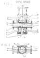
- such a valve (1) comprises a valve body (2), and different connection paths. More specifically, the valve (1) comprises an upstream channel (3) and a downstream channel (4), located in the extension of each other, and intended to be connected to a main pipe not shown. The fluid flowing in the main pipe flows from the track upstream (3) to the downstream channel (4).
- the valve (1) also includes a third connection channel (5) intended to be connected to a secondary pipe not represented. The third connection channel (5) is arranged so perpendicular to the axis (6) of the main pipe.
- the valve (1) also comprises a movable shutter member (7) capable of moving perpendicular to the main line, and in the direction (8) of the secondary line.
- This organ shutter (7) is slidably mounted inside a housing (9) provided for this purpose between the upstream and downstream routes.
- the faces (11, 12) of the shutter member (7) which are oriented towards the upstream (3) and downstream (4) tracks are flat.
- the lateral faces (13, 14) connecting these planar faces (11, 12) are cylindrical, and of diameter substantially equal to the inside diameter of the third channel (5) of connection, except for mechanical clearances.
- the shutter member (7) has two orifices separate through (15, 16).
- the first orifice (15) located in the upper part of the shutter member (7) has a cylindrical profile, of diameter equal to that of upstream (3) and downstream (4) tracks of the main pipe.
- the pipe main has a constant diameter inside the valve, which allows the passage of a cleaning scraper (20).
- the shutter member (7) also has a second through hole (16) located in the lower part.
- This second orifice (16) opens into the lower part (17) of the shutter member in the direction of the third connection channel (5).
- This orifice also opens on the side of the upstream track (3). It has for this purpose two drilled holes (18, 19) on the flat face (11) of the shutter member, these holes (18, 19) opening into a cavity (21) in relation to the outlet (17) of the orifice.
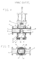
- the presence of the through holes (18, 19) makes it possible to define a portion flush (23) on the surface (11) facing the upstream track (3). As illustrated in Figure 4, this portion (23) blocks the scraper (20) which is located in the upstream track (3) by preventing it from entering the second orifice (16).
- valve (2) according to the invention is not limited to this single geometry using two through holes to enter the second hole but it also covers all variants in which the face of the organ shutter opposite the upstream track has a portion blocking the progress of the scraper.
- the ends of the upstream (3) and downstream (4) tracks coming opposite the shutter member (7) are equipped with sealing means (25, 26). More specifically, the ends of the upstream and downstream routes have a cylindrical housing (27, 28) inside which an O-ring is placed (25, 26).
- the invention is not limited to this single form of seal toric, but covers other variants which ensure sealing between the shutter member and the upstream and downstream channels, these joints being able to be a seat in polytetrafluoroethylene, an inflatable seal or the like.
- the displacement of the shutter member (7) can be obtained by different means.
- the shutter member (7) is connected by a rod (30) to an arm which can be connected to different mechanisms actuating. It can be hydraulic, pneumatic cylinders. It could be electric actuators or even manual actuation.
- the shutter member (7) In operation, when the shutter member (7) is in the low position, corresponding to a closed valve position, and as illustrated in FIG. 1, the first orifice (15) of the shutter member (7) is in alignment with the upstream (3) and downstream (4) channels so that the fluid and a scraper (20) can circulate inside the main pipe.
- the watertightness between the main track and the secondary track is ensured by the two O-rings (25, 26) which prevent any penetration of fluid in the direction of the third connection channel (5).
- the O-ring located between the upstream track (3) and the closure member (7) prevents leaks to the outside, especially in the upper part of the valve body (2).
- the presence of the central portion (18) the shutter member (7) blocks the progress of the scraper (20) and therefore prevents the penetration of the latter inside the second orifice (16), which eliminates the risk of the scraper (20) opposing the movements of the shutter member (7).
- the third route of connection (5) is equipped with different cleaning nozzles (30-32). These nozzles are supplied by an externally not shown pipe. Two of these nozzles (30, 32) are oriented so as to spray the inside of the body of the third way (5).
- the central nozzle (31) is directed so that it allows spraying the second orifice (16) of the shutter member (7). Its orientation also allows the cleaning jet (18) to pass through one of the through holes in the second orifice (16) so as to clean the front part of the scraper (20).
- valve according to the invention has multiple advantages and in particular that of ensuring an optimal seal between the main track and the secondary track, while allowing the passage of a scraper cleaning.
Landscapes
- Engineering & Computer Science (AREA)
- General Engineering & Computer Science (AREA)
- Mechanical Engineering (AREA)
- Chemical & Material Sciences (AREA)
- Combustion & Propulsion (AREA)
- Lift Valve (AREA)
Applications Claiming Priority (2)
| Application Number | Priority Date | Filing Date | Title |
|---|---|---|---|
| FR0103177 | 2001-03-08 | ||
| FR0103177A FR2821914B1 (fr) | 2001-03-08 | 2001-03-08 | Vanne |
Publications (1)
| Publication Number | Publication Date |
|---|---|
| EP1239211A1 true EP1239211A1 (de) | 2002-09-11 |
Family
ID=8860896
Family Applications (1)
| Application Number | Title | Priority Date | Filing Date |
|---|---|---|---|
| EP02356041A Withdrawn EP1239211A1 (de) | 2001-03-08 | 2002-02-28 | Molchfähiges Ventil mit Reinigungsvorrichtung |
Country Status (3)
| Country | Link |
|---|---|
| US (1) | US6725875B2 (de) |
| EP (1) | EP1239211A1 (de) |
| FR (1) | FR2821914B1 (de) |
Families Citing this family (6)
| Publication number | Priority date | Publication date | Assignee | Title |
|---|---|---|---|---|
| DE10235102B4 (de) * | 2002-08-01 | 2006-07-27 | Lac Tec GmbH Gesellschaft für moderne Lackiertechnik | Lackiereinrichtung mit einer molchbaren Ventileinrichtung |
| US7971854B2 (en) * | 2007-09-24 | 2011-07-05 | Griswold Controls Inc | Replaceable valve shaft sealing system |
| EP3810974B1 (de) * | 2018-06-22 | 2022-08-24 | Vetco Gray Scandinavia AS | Molchstarter |
| CN112855990B (zh) * | 2020-12-31 | 2022-09-30 | 重庆磐恒阀门有限公司 | 一种球形自清洁燃气切断阀 |
| CN113482710A (zh) * | 2021-07-26 | 2021-10-08 | 梁坤 | 一种煤矿膏体充填旋布阀 |
| US12044342B2 (en) * | 2021-12-28 | 2024-07-23 | Cytiva Us Llc | Fluid connector with slidable member |
Citations (5)
| Publication number | Priority date | Publication date | Assignee | Title |
|---|---|---|---|---|
| US3063079A (en) | 1960-03-31 | 1962-11-13 | Panhandle Eastern Pipe Line Co | Combination valve and cleaning ball launcher for use in pressure flow lines |
| US3068901A (en) | 1960-04-22 | 1962-12-18 | Acf Ind Inc | Three way gate valve |
| US5113895A (en) | 1988-12-20 | 1992-05-19 | Fmc Corporation | Three way valve and distribution pipe comprising same, both adapted to be cleaned by scraping |
| US5193572A (en) | 1991-06-27 | 1993-03-16 | Fmc Corporation | Pig-compatible three-way butterfly valve |
| EP0563853A1 (de) | 1992-04-01 | 1993-10-06 | ABK ARMATURENBAU GmbH | Absperr- oder Umlenkarmatur mit molchbarem Durchgang |
Family Cites Families (9)
| Publication number | Priority date | Publication date | Assignee | Title |
|---|---|---|---|---|
| US2305724A (en) * | 1940-12-31 | 1942-12-22 | Standard Oil Co | Valve |
| US2917069A (en) * | 1956-08-27 | 1959-12-15 | Bolton John W & Sons Inc | Adjustable port valve |
| US2930395A (en) * | 1956-12-28 | 1960-03-29 | Phillips Petroleum Co | Valve having improved flushing means |
| US3133554A (en) * | 1961-12-08 | 1964-05-19 | Ladish Co | Valve having a seat cleaning feature |
| US3146477A (en) * | 1963-04-22 | 1964-09-01 | Panhandle Eastern Pipe Line Co | Combination valve and cleaning ball launcher |
| US4249560A (en) * | 1979-03-28 | 1981-02-10 | Raque Glen F | Automatic valve clearoff |
| JPS5920062B2 (ja) * | 1980-01-25 | 1984-05-10 | 株式会社クボタ | スリ−ブ弁 |
| FR2640717B1 (fr) * | 1988-12-20 | 1991-04-05 | Fmc Europe | Vanne a deux voies destinee a etre montee en aval d'une conduite raclable de distribution de fluide |
| FR2756905B1 (fr) * | 1996-12-10 | 1998-12-31 | Cellier Groupe Sa | Vanne hydraulique et installation de distribution de liquides equipee de telles vannes |
-
2001
- 2001-03-08 FR FR0103177A patent/FR2821914B1/fr not_active Expired - Lifetime
-
2002
- 2002-02-28 EP EP02356041A patent/EP1239211A1/de not_active Withdrawn
- 2002-03-06 US US10/091,902 patent/US6725875B2/en not_active Expired - Lifetime
Patent Citations (5)
| Publication number | Priority date | Publication date | Assignee | Title |
|---|---|---|---|---|
| US3063079A (en) | 1960-03-31 | 1962-11-13 | Panhandle Eastern Pipe Line Co | Combination valve and cleaning ball launcher for use in pressure flow lines |
| US3068901A (en) | 1960-04-22 | 1962-12-18 | Acf Ind Inc | Three way gate valve |
| US5113895A (en) | 1988-12-20 | 1992-05-19 | Fmc Corporation | Three way valve and distribution pipe comprising same, both adapted to be cleaned by scraping |
| US5193572A (en) | 1991-06-27 | 1993-03-16 | Fmc Corporation | Pig-compatible three-way butterfly valve |
| EP0563853A1 (de) | 1992-04-01 | 1993-10-06 | ABK ARMATURENBAU GmbH | Absperr- oder Umlenkarmatur mit molchbarem Durchgang |
Also Published As
| Publication number | Publication date |
|---|---|
| US6725875B2 (en) | 2004-04-27 |
| FR2821914A1 (fr) | 2002-09-13 |
| FR2821914B1 (fr) | 2004-02-20 |
| US20020124884A1 (en) | 2002-09-12 |
Similar Documents
| Publication | Publication Date | Title |
|---|---|---|
| US5188151A (en) | Flow diverter valve | |
| EP0520852B1 (de) | Molchfähiges 3-Wege-Klappenventil | |
| BE1008217A6 (fr) | Valve a deversoir a trois voies. | |
| EP3581836B1 (de) | Flüssigkeitskupplung | |
| WO2001051216A2 (fr) | Installation de projection de produit de revetement | |
| MX2010012095A (es) | Aparato de limpieza de conductos. | |
| FR2821914A1 (fr) | Vanne | |
| EP3742037B1 (de) | Anschlussbuchse eines fluidanschlusses, untereinheit zum anschliessen und anschluss, der eine solche anschlussbuchse umfasst | |
| FR2658578A1 (fr) | Dispositif a soupape d'arret evitant les fuites. | |
| EP0403345B1 (de) | Verbindungsvorrichtung zwischen zwei Rohrleitungsteilen | |
| FR2901340A1 (fr) | Agencement de distributeur hydraulique sous forme de cartouche | |
| US4623002A (en) | Polymer control valve | |
| EP1352190A1 (de) | Pneumatisch angesteuertes ventil | |
| FR2497321A1 (fr) | Raccord tournant a fluide permettant le passage de pistons-racleurs | |
| FR2957999A1 (fr) | Piston avec un conduit sous joint | |
| FR2515841A1 (fr) | Dispositif de selection de pression maximale | |
| CN101297142B (zh) | 管接头结构 | |
| EP3609745B1 (de) | Druckbegrenzer auf einer vorrichtung zur abgabe einer windschutzscheibenwaschflüssigkeit für ein kraftfahrzeug | |
| US6126047A (en) | Dispensing nozzle | |
| EP0848195B1 (de) | Hydraulisches Ventil und Dispensiereinrichtung für Flüssigkeiten mit solchen Ventilen | |
| EP1531298B1 (de) | Abzweigungsvorrichtung, pneumatisches Leitungssystem mit einer solchen Abzweigungsvorrichtung, Anordnung mit einem solchen Leitungssystem | |
| US7044153B2 (en) | Varnishing installation | |
| FR2486240A1 (fr) | Vanne pour prise d'echantillons | |
| FR2670270A1 (fr) | Poste de purge monobloc a robinets d'isolement incorpores. | |
| JPH09206721A (ja) | 自動洗浄装置 |
Legal Events
| Date | Code | Title | Description |
|---|---|---|---|
| PUAI | Public reference made under article 153(3) epc to a published international application that has entered the european phase |
Free format text: ORIGINAL CODE: 0009012 |
|
| AK | Designated contracting states |
Kind code of ref document: A1 Designated state(s): AT BE CH CY DE DK ES FI FR GB GR IE IT LI LU MC NL PT SE TR |
|
| AX | Request for extension of the european patent |
Free format text: AL;LT;LV;MK;RO;SI |
|
| 17P | Request for examination filed |
Effective date: 20030108 |
|
| AKX | Designation fees paid |
Designated state(s): AT BE CH CY DE DK ES FI FR GB GR IE IT LI LU MC NL PT SE TR |
|
| 17Q | First examination report despatched |
Effective date: 20041220 |
|
| STAA | Information on the status of an ep patent application or granted ep patent |
Free format text: STATUS: THE APPLICATION IS DEEMED TO BE WITHDRAWN |
|
| 18D | Application deemed to be withdrawn |
Effective date: 20050503 |