EP1239215B1 - Dispositif d'éclairage pour l' illumination de locaux - Google Patents
Dispositif d'éclairage pour l' illumination de locaux Download PDFInfo
- Publication number
- EP1239215B1 EP1239215B1 EP02005485A EP02005485A EP1239215B1 EP 1239215 B1 EP1239215 B1 EP 1239215B1 EP 02005485 A EP02005485 A EP 02005485A EP 02005485 A EP02005485 A EP 02005485A EP 1239215 B1 EP1239215 B1 EP 1239215B1
- Authority
- EP
- European Patent Office
- Prior art keywords
- light
- hollow body
- wall
- scattering
- luminary
- Prior art date
- Legal status (The legal status is an assumption and is not a legal conclusion. Google has not performed a legal analysis and makes no representation as to the accuracy of the status listed.)
- Expired - Lifetime
Links
Images






Classifications
-
- F—MECHANICAL ENGINEERING; LIGHTING; HEATING; WEAPONS; BLASTING
- F21—LIGHTING
- F21V—FUNCTIONAL FEATURES OR DETAILS OF LIGHTING DEVICES OR SYSTEMS THEREOF; STRUCTURAL COMBINATIONS OF LIGHTING DEVICES WITH OTHER ARTICLES, NOT OTHERWISE PROVIDED FOR
- F21V7/00—Reflectors for light sources
- F21V7/22—Reflectors for light sources characterised by materials, surface treatments or coatings, e.g. dichroic reflectors
-
- F—MECHANICAL ENGINEERING; LIGHTING; HEATING; WEAPONS; BLASTING
- F21—LIGHTING
- F21S—NON-PORTABLE LIGHTING DEVICES; SYSTEMS THEREOF; VEHICLE LIGHTING DEVICES SPECIALLY ADAPTED FOR VEHICLE EXTERIORS
- F21S11/00—Non-electric lighting devices or systems using daylight
-
- F—MECHANICAL ENGINEERING; LIGHTING; HEATING; WEAPONS; BLASTING
- F21—LIGHTING
- F21S—NON-PORTABLE LIGHTING DEVICES; SYSTEMS THEREOF; VEHICLE LIGHTING DEVICES SPECIALLY ADAPTED FOR VEHICLE EXTERIORS
- F21S19/00—Lighting devices or systems employing combinations of electric and non-electric light sources; Replacing or exchanging electric light sources with non-electric light sources or vice versa
-
- F—MECHANICAL ENGINEERING; LIGHTING; HEATING; WEAPONS; BLASTING
- F21—LIGHTING
- F21V—FUNCTIONAL FEATURES OR DETAILS OF LIGHTING DEVICES OR SYSTEMS THEREOF; STRUCTURAL COMBINATIONS OF LIGHTING DEVICES WITH OTHER ARTICLES, NOT OTHERWISE PROVIDED FOR
- F21V7/00—Reflectors for light sources
- F21V7/0008—Reflectors for light sources providing for indirect lighting
-
- F—MECHANICAL ENGINEERING; LIGHTING; HEATING; WEAPONS; BLASTING
- F21—LIGHTING
- F21S—NON-PORTABLE LIGHTING DEVICES; SYSTEMS THEREOF; VEHICLE LIGHTING DEVICES SPECIALLY ADAPTED FOR VEHICLE EXTERIORS
- F21S8/00—Lighting devices intended for fixed installation
- F21S8/04—Lighting devices intended for fixed installation intended only for mounting on a ceiling or the like overhead structures
-
- F—MECHANICAL ENGINEERING; LIGHTING; HEATING; WEAPONS; BLASTING
- F21—LIGHTING
- F21V—FUNCTIONAL FEATURES OR DETAILS OF LIGHTING DEVICES OR SYSTEMS THEREOF; STRUCTURAL COMBINATIONS OF LIGHTING DEVICES WITH OTHER ARTICLES, NOT OTHERWISE PROVIDED FOR
- F21V13/00—Producing particular characteristics or distribution of the light emitted by means of a combination of elements specified in two or more of main groups F21V1/00 - F21V11/00
- F21V13/02—Combinations of only two kinds of elements
- F21V13/04—Combinations of only two kinds of elements the elements being reflectors and refractors
-
- F—MECHANICAL ENGINEERING; LIGHTING; HEATING; WEAPONS; BLASTING
- F21—LIGHTING
- F21W—INDEXING SCHEME ASSOCIATED WITH SUBCLASSES F21K, F21L, F21S and F21V, RELATING TO USES OR APPLICATIONS OF LIGHTING DEVICES OR SYSTEMS
- F21W2131/00—Use or application of lighting devices or systems not provided for in codes F21W2102/00-F21W2121/00
- F21W2131/40—Lighting for industrial, commercial, recreational or military use
- F21W2131/402—Lighting for industrial, commercial, recreational or military use for working places
-
- F—MECHANICAL ENGINEERING; LIGHTING; HEATING; WEAPONS; BLASTING
- F21—LIGHTING
- F21Y—INDEXING SCHEME ASSOCIATED WITH SUBCLASSES F21K, F21L, F21S and F21V, RELATING TO THE FORM OR THE KIND OF THE LIGHT SOURCES OR OF THE COLOUR OF THE LIGHT EMITTED
- F21Y2103/00—Elongate light sources, e.g. fluorescent tubes
- F21Y2103/30—Elongate light sources, e.g. fluorescent tubes curved
- F21Y2103/33—Elongate light sources, e.g. fluorescent tubes curved annular
-
- F—MECHANICAL ENGINEERING; LIGHTING; HEATING; WEAPONS; BLASTING
- F21—LIGHTING
- F21Y—INDEXING SCHEME ASSOCIATED WITH SUBCLASSES F21K, F21L, F21S and F21V, RELATING TO THE FORM OR THE KIND OF THE LIGHT SOURCES OR OF THE COLOUR OF THE LIGHT EMITTED
- F21Y2113/00—Combination of light sources
- F21Y2113/10—Combination of light sources of different colours
- F21Y2113/13—Combination of light sources of different colours comprising an assembly of point-like light sources
-
- F—MECHANICAL ENGINEERING; LIGHTING; HEATING; WEAPONS; BLASTING
- F21—LIGHTING
- F21Y—INDEXING SCHEME ASSOCIATED WITH SUBCLASSES F21K, F21L, F21S and F21V, RELATING TO THE FORM OR THE KIND OF THE LIGHT SOURCES OR OF THE COLOUR OF THE LIGHT EMITTED
- F21Y2115/00—Light-generating elements of semiconductor light sources
- F21Y2115/10—Light-emitting diodes [LED]
Definitions
- the present invention relates to a luminous element for illuminating rooms with a hollow body bounded by a wall, which is provided for multiple reflection of light inside with reflective inner surfaces, wherein the inner surfaces of the hollow body have a reflectance of at least 90% and are designed to be light scattering and in the Wall of the hollow body is provided at least one wall which passes through the light exit opening.
- Luminaires for the illumination of rooms are known in the prior art in a wide variety and with various forms.
- the different forms of luminaires depend on the way they are used. Here you can generally distinguish between luminaires, which serve the selective illumination of a particular area.
- luminaires which serve the selective illumination of a particular area.
- Another type of luminaires serves the most uniform possible illumination of premises.
- ceiling lights, arrangement of fluorescent tubes, etc. are often used.
- the task of the selective illumination of certain limited areas as well as the uniform illumination of rooms often occurs simultaneously in closed rooms.
- various types of luminous bodies often have to be used in combination to solve these problems.
- the documents DE 4 439 507 A1 and US Pat. No. 4,459,642 A disclose luminous bodies with hollow bodies in which the hollow bodies have reflective inner surfaces. In the luminous bodies shown in these documents, both sunlight and artificial light is irradiated. In the hollow body there is a leveling or mixing of the light radiated by the different light sources. This leveling is based on a multiple reflection of the incident light in the hollow body, on its reflective inner surfaces. In US Pat. No. 4,459,642 A, the light emission from the luminous element takes place via semi-transparent regions in the wall of the hollow body and in DE 4 439 507 A1 via so-called light exit systems, in which the light can also emerge via semi-transparent regions.
- All the luminous bodies shown in these documents have the disadvantage that, although they are not used for uniform and sufficiently bright room illumination, they are not suitable for the purpose of illuminating limited subareas with increased light requirements, such as, for example. can be used to illuminate workplaces.
- the luminance produced in the respective hollow bodies is not sufficient in the case of the above-mentioned luminous bodies known from the prior art.
- GB 2340215 A discloses a generic luminous element for illuminating rooms with a hollow body bounded by a wall, which is provided for multiple reflection of light inside with reflective inner surfaces, wherein the inner surfaces of the hollow body have a reflectance of at least 90% and are designed to light scattering and in the wall of the hollow body at least one wall which passes through the light exit opening is provided.
- the object of the invention is to further improve the effectiveness of the generic luminous body.
- the luminous body has a wall of the hollow body which passes through the light exit opening.
- This targeted light extraction can be used for concentrated illumination of limited areas, but also for the targeted illumination of rooms.
- overall a significantly improved illumination is achieved than with the known in the prior art hollow body lamps.
- the use of light exit openings is possible only by a sufficiently high luminance in the interior of the luminous element.
- the high luminance and thus an economical operation of such lamps with a corresponding high luminaire efficiency is only possible by the inventive reflectance of the inner surfaces of the hollow body of at least 90%. Due to the light-scattering design of the inner surfaces of the hollow body is also achieved on the one hand, that light sources or other components within the hollow body are not displayed to the outside.
- the light-scattering effect of the inner surfaces results in that only diffusely diffused light is radiated from the luminous body. Under light scattering not only a perfect direction independent ideal scattering but in general an expansion of the reflected light beam is called. Overall, the light-scattering effect according to the invention is characterized in that the light leaving the luminous element no longer has preferred directions. This can, as stated below, be achieved by various measures.
- the ratio of the inner surface of the wall of the hollow body to the sum of all surfaces of all openings, preferably all light exit openings in the wall of the hollow body is greater than 5: 1, preferably greater than 10: 1, is.
- a ratio of the surface of the wall of the hollow body to the sum of all surfaces of all openings in the wall of the hollow body greater than 20: 1 or greater than 30: 1 or preferably even greater than 40: 1 strive.
- a luminous element can only be operated effectively if its efficiency Eta is above a certain minimum value.
- the efficiency Eta depends on the inner surface of the wall of the sum of all surfaces of all openings and the reflectance of the inner surfaces.
- the efficiency Eta depends on the inner surface of the wall of the sum of all surfaces of all openings and the reflectance of the inner surfaces.
- the efficiency Eta is generally defined as the ratio of the luminous flux which exits the hollow body through A1 to the luminous flux of the feeding light sources.
- the area of the light exit opening (s) to be kept as small as possible, since this further simplifies the directing of the light flux emitted by the light exit openings through a corresponding optical system. This is the case, for example, if further light-directing reflectors are to be used. From the above formula for the efficiency Eta results, for example, that when a Efficiency of 65% with the known in the prior art good reflectance of about 85% should be achieved, the area ratio f should be more than 32%.
- the result for the area ratio f is a value of 9.7%, which in turn means that the surface of the light exit openings can be kept much smaller thanks to the high reflectance, without sacrificing the efficiency in Purchase would have to be taken. With correspondingly higher degrees of reflection, correspondingly smaller light exit openings can be used with constant efficiency.
- a preferred embodiment of the filament according to the invention provides that in the luminous body at least one light inlet opening preferably to the inlet of daylight and / or sunlight and / or at least one artificial light source is arranged.
- the hollow body with a diffusely reflecting inner surface can also have one or more light entry opening (s) in order to feed natural or artificial light from outside through the openings into the hollow body as an alternative or in addition to an integrated light source. Due to the multiple reflection of the light on the inner surfaces of the hollow body, the position of the light entry opening or the artificial light source in the hollow body of the luminous element is independent of the overall luminous effect emitted by the luminous element. This allows a very great freedom in the design of the shape of the filament.
- the light distribution emerging from the light exit opening is always diffused and independent of the light distribution of the light source located in the hollow body and independent of the light distribution of the light source flowing through the inlet opening. If both natural and artificial light is irradiated into the hollow body, it can be maintained by a corresponding control of the proportion of artificial light, a nearly uniform intensity of the light emitted by the lamp with maximum sunlight proportion over the entire daily routine indoors.
- a preferred embodiment provides that two or more light sources or light inlet openings, preferably for the entrance of daylight and / or sunlight are arranged in the luminous body, wherein the multiple reflection at the highly reflective inner surfaces, the light introduced into the hollow body, preferably almost completely, mixes.
- differently colored light whether it is irradiated by one or different light sources in the hollow body of the filament, mixed in the way by multiple reflections of the light on the inner surfaces of the hollow body, that it always leaves the light exit surfaces as a mixed light, preferably white light.
- daylight with artificial light or different colored light from different light sources in the hollow body of the luminous body can be mixed specifically.
- an inventive embodiment of the luminous element can also be used to eliminate the directional dependence of the intensity of the light, which is caused by the emission characteristic of a light source.
- a preferred embodiment provides that at least one light source is provided which emits light of different intensity in different spatial directions, wherein the multiple reflection of the light at the highly reflective inner surface of the hollow body leads to the fact that the intensity of the luminous body - preferably via at least one light exit opening - emitted light is completely independent of direction.
- each light source parallel sunlight, diffused fluorescent light, incandescent light, etc.
- a "diffused surface light source” regardless of their original radiation characteristics, which - is easy to control - preferably with reflectors.
- the achieved by the multiple reflection leveling the intensity, the direction and the color content of the light emitted by the light source or sources is particularly favorable for the use of different-colored point and line light sources or different colored high-pressure discharge lamps.
- the leveling effect can also be used with the use of multiple semiconductor light sources (e.g., LEDs).
- the highly reflective properties of the inner surface of the hollow body according to the invention can, as stated above, be achieved by various measures.
- a preferred variant provides that the light-scattering highly reflective inner surfaces at least partially, preferably completely, have a light-diffusing preferably white film.
- a white film can be made, for example, from polytetrafluoroethylene (PTFE).
- PTFE polytetrafluoroethylene
- the light-scattering highly reflecting inner surfaces at least partially, preferably completely have a light-scattering roughened, frosted or etched surface.
- the light-scattering highly reflective inner surfaces at least partially preferably a completely - preferably formed of knobs, Learnfachkantung, grooves or other straight or oblique irregularities formed light-scattering macroscopic surface structure.
- the macroscopic surface structure consists of glossy or high-gloss material.
- An example of this variant is e.g. It is to use a high-gloss film or a high-gloss reflector sheet, the surface of which is grooved, grooved, creased multiple or the like. In this way, reflectivities of the inner surfaces of the hollow body greater than 95% or 98% can be achieved.
- all these different variants of the design of the highly reflective light-scattering inner surfaces have in common that the light ultimately leaving the luminous body through the light exit opening is pleasantly diffused.
- a particularly preferred embodiment provides that at least one light-guiding, preferably parabolically shaped, mirror optics or another light-deflecting device is arranged in the region of the light exit opening of the luminous element and limits the exiting light angularly.
- refractor optics or diffractor optics may also be used.
- diaphragms can also be provided in the interior of the hollow body, these diaphragms preventing the direct view of the light source or the light inlet opening in the hollow body.
- a preferred embodiment of the luminous body according to the invention provides that it has a preferably diffusely scattering, for the non-reflected light component substantially translucent wall. This creates a particularly uniform and pleasant illumination of a room. Due to the high reflectance generated, highly concentrated luminance within the Cavity of the filament extends from the very small not reflected on the inner surface of the hollow body but transmitted through the wall diffusely scattered light component for a pleasant for the human eye uniform illumination of a room. As a result of the transmission of the non-reflecting residual light through the wall, the efficiency of the luminous element is further increased since almost the entire light, which is also always fed in, leaves the luminous element as useful light.
- the wall or the luminous body absorbs as little light energy in the form of heat.
- the low heat absorption can be achieved by a high degree of transmittance.
- a good transmission of the infrared wavelength ranges of the light is in the foreground.
- cooling fins or the like may be provided on the hollow body.
- another variant provides thermal shock protection e.g. in the form of mesh, plastic ribs or the like.
- the luminous element is a preferably cuboidal hollow body, which is lined with a highly reflective film, wherein in the hollow body at least one lamp or at least one light inlet opening, - preferably for daylight and / or sunlight - and at least one aperture is arranged , wherein the direct radiation component hidden is.
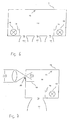
- Fig. 1 shows a simple incandescent lamp in which no light is emitted in the direction of the socket of the incandescent lamp.
- This is a schematic example of the fact that light sources typically have a directionality in the radiated intensity of the light.
- Fig. 2 this is illustrated by means of a light source 2 located in a light source 1.
- the light source 1 in FIG. 2 emits light of different intensity in different directions. This ultimately results in the fact that in the angular range perpendicularly below the light source 1 or the light exit opening 3 of the luminous element 2 light is emitted with a relatively high intensity.
- the light beam 4 In contrast, the intensity of the emitted light decreases with increasing angle against the illustrated by beam 4 vertical radiation direction. This reduces the light intensity towards the sides.
- This laterally emitted light of lower intensity is represented by the beams 5 and 6 by way of example.
- FIG. 3 On the basis of a schematic representation of a luminous body with a discharge lamp.
- a discharge lamp 8 forms at the bottom of a lamp sump 9. This changes the spectral content (color) of the light passing through it.
- the light generated by the gas discharge lamp is filtered as it passes through the lamp sump 9 so that it leaves the gas discharge lamp down as a brown light.
- Such a light beam with brown light is shown schematically as beam 10 in FIG.
- the beam path 11 does not pass through the lamp sump and thus the light passing along its path is not filtered by the lamp sump. It leaves on its way via a reflection on the reflector 7, the gas discharge lamp as blue light.
- the total light effect of such a luminous element is thus characterized by the fact that disturbing color spots exist on the use plane 12, since the use plane 12 is illuminated in regions with differently colored light.
- the light emitted by the light source 13 is reflected a plurality of times at the light-scatteringly highly reflective inner surface 14 of the hollow body 15 before part of the light leaves the luminous body through the light exit opening 16.
- the light-scattering highly reflective properties of the inner surfaces 14 can in all embodiments, e.g. be achieved by suitable coatings, macroscopic surface structures or the bonding of suitable films.
- Such films may e.g. polytetraethylene films or multilayer polymeric films having an outer layer of polyethylene naphthalate (PEN).
- a mirror optics 17 or another light-directing device can be attached at the light exit opening 16 at the light exit opening 16. It is provided that a wide variety of mirror grid optics are attached to the light exit opening and thus a variety of different adapted to the particular needs lighting effects can be achieved.
- the diaphragm 18 prevents light from directly leaving the lamp 13 through the light exit opening 16, the luminous body. This prevents a person from being dazzled by light emitted directly from the light source. That by the Light exit opening 16 light leaving the filament has been reflected light-scattering several times before leaving the filament on the highly reflective inner surface 14 and is thus a completely direction independent, spectrally completely mixed, pleasant diffused light.
- diffuse light can also be emitted by the luminous body through the wall of the hollow body 15 when the wall of the hollow body 15 is designed to be translucent. It should be noted that despite the high reflectance of the inner surface 14 of the hollow body 15 sufficient for the illumination of a room amount of light can be transmitted through the highly reflective inner surface and the wall of the hollow body 15, since on a suitable wall whose absorption is negligible and on the other hand, such a high luminance in the interior 19 of the hollow body is produced by the multiple reflection, that the low percentage of the transmitted residual light is still sufficient for pleasant illumination of rooms.
- the ratio between the light exiting through the wall 15 of the luminous element and the amount of light exiting through the light exit opening 16 is essentially determined by the ratio of the area of the light exit opening 16 and the total area of the highly reflective inner wall 14 of the hollow body 15 and can be related to the respective one Need to be adjusted.
- precise control is possible between the proportions of the general room lighting with pleasantly diffused light and the concentrated illumination of limited areas.
- a glare limitation in all spatial directions for angular ranges above 65 ° to the vertical to less than 1000 cd / m 2 can be achieved for office workplaces.
- 5 shows a variant with two light sources 13, in which the hollow body 15 has an overall oval cross-sectional shape and a mirror-grid optical system 17 integrated in the wall.
- 6 shows schematically a variant with a plurality of light exit openings 16.
- FIG. 7 shows an embodiment according to the invention in which parallel sunlight enters the interior 19 of the hollow body 15 through a light entry opening 20.
- the incoming sunlight is transformed into a completely direction-independent diffused light and then exits from the light exit opening 16.
- the wall 15 of the hollow body may be made translucent, whereby a part of the light is transported through the wall 15 of the filament and emitted as diffusely scattered light.
- a matched to the particular needs mirror grid optics 17 are attached to the light exit opening 16, as in the embodiment in Fig. 4, a matched to the particular needs mirror grid optics 17 are attached.
- the aperture 18 in turn prevents the sunlight entering through the light inlet opening 20 directly leaves the luminous element through the light exit opening 16 before it is repeatedly reflected on the inner walls 14.
- the transport of sunlight to the luminous element can, as known in the prior art, take place in a channel made of fully reflecting prisms or in optical waveguides. As an alternative, highly reflective mirror materials are also possible.
- prior art devices may be used as the system for collecting, bundling and transporting the sunlight to the room to be illuminated.
- a preferred embodiment for this purpose provides that the luminous element is optically connected via a light pipe to a heliostat which directs the sunlight into the luminous body via the light pipe.
- the heliostat according to the prior art consists essentially of an array of mirrors whose orientation is tracked the course of the sun, so that as long as possible the optimum amount of light is coupled into the light pipe.
- an additional artificial light source 13 can be attached.
- This combination of at least one light entrance opening and at least one additional light source is intended to schematically illustrate the multitude of possible combinations between artificial and natural light or various artificial light sources with different emission characteristics and emitted radiation distributions of the light.
- FIG. 8 once again illustrates a variant for utilizing the mixing effect of the multiple reflection of the incident light in the hollow body of the luminous body according to the invention.
- a multiplicity of small light sources eg LEDs of different colors
- LEDs of different colors are arranged in the hollow body.
- FIG. 9 shows a variant embodiment in which a fluorescent tube is arranged in the hollow body as light source 13.
- FIG. 10 schematically shows a variant in which the light-scattering effect of the inner surfaces 14 of the hollow body is achieved by a macroscopic surface structure. In this variant, the inner surfaces can even be made shiny, since the light-scattering effect is achieved by the surface structure.
- Other favorable shapes are composed of flat surface segments or of cylindrically rolled surface segments and / or conically rolled surface segments. These shapes are advantageous because they can be easily made from a sheet material by rolling, edging and joining.
- Other favorable forms are essentially convex polyhedra, such as regular polyhedra (tetrahedral cubes, octahedra, decahedra and icosahedra) and distorted regular polyhedra (eg cuboids and general pyramids). These embodiments have the advantage that they consist of a few flat Obe perennialsegmenten and thus also can be easily manufactured.
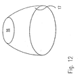
- FIGS. 11 and 12 show, as a variant, different mirror optics 17.
- a substantially plate-shaped transparent body with schematically defractive structures such as, for example, is used to influence the exiting light. Prisms, truncated pyramids or totally reflective cavities with optionally partially reflective surface coatings used.
- the refractive structures 21 have the advantage that they can be made flat and small and have hardly any absorption losses. The light portions reflected back into the cavity emerge from the cavity again after being reflected several times at the various internal surfaces.
- optical diffraction structures 14 consists of a substantially plate-shaped body with schematically drawn optical diffraction structures. These structures are known as holographic optical elements or defractive optical elements or as computer-generated diffraction structures as so-called “kinoforms" or "binary optics".
- the defractive structures have the same advantages as refractive structures 21. In addition, they can be duplicated and manufactured very inexpensively.
Landscapes
- Engineering & Computer Science (AREA)
- General Engineering & Computer Science (AREA)
- Life Sciences & Earth Sciences (AREA)
- Sustainable Development (AREA)
- Non-Portable Lighting Devices Or Systems Thereof (AREA)
- Optical Fibers, Optical Fiber Cores, And Optical Fiber Bundles (AREA)
- Light Guides In General And Applications Therefor (AREA)
- Vessels And Coating Films For Discharge Lamps (AREA)
Claims (11)
- Dispositif d'éclairage pour l'illumination de locaux comprenant un corps creux limité par une paroi (15), qui est doté de surfaces intérieures réfléchissantes pour la réflexion multiple de la lumière à l'intérieur, les surfaces intérieures (14) du corps creux présentant un degré de réflexion d'au moins 90 % et étant conçues diffusantes et au moins une ouverture de sortie de lumière (16) traversant la paroi (15) étant prévue dans la paroi (15) du corps creux, caractérisé en ce que, à partir de la surface intérieure A0 de la paroi (15) du corps creux, de la somme A1 de toutes les surfaces de toutes les ouvertures (16, 20) dans la paroi (15) et du degré de réflexion Rho, on obtient lors du calcul du rendement Eta selon la formule Eta = Rho x f / (1- Rho (1-f)) un rendement Eta d'au moins 40 %, de préférence d'au moins 65 %, f étant égal à A1 / (A1 + A0) ; et en ce que le rapport entre la surface intérieure de la paroi (15) du corps creux et la somme de toutes les surfaces de toutes les ouvertures, de préférence de toutes les ouvertures de sortie de lumière (16), dans la paroi (15) du corps creux est supérieur à 5:1, de préférence supérieur à 10:1.
- Dispositif d'éclairage selon la revendication 1, caractérisé en ce que les surfaces intérieures (14) du luminaire présentent un degré de réflexion supérieur à 95 %, de préférence supérieur à 98 %.
- Dispositif d'éclairage selon l'une quelconque des revendications 1 à 2, caractérisé en ce que au moins une ouverture d'entrée de lumière (20), de préférence pour l'entrée de la lumière du jour et/ou de la lumière du soleil - et/ou au moins une source de lumière (13) artificielle est disposée dans ce luminaire.
- Dispositif d'éclairage selon l'une quelconque des revendications 1 à 3, caractérisé en ce que dans le luminaire sont disposées deux ou plusieurs sources de lumière (13) ou ouvertures d'entrée de lumière (20), de préférence pour l'entrée de la lumière du jour et/ou de la lumière du soleil, la réflexion multiple sur les surfaces intérieures (14) à haute réflexion mélangeant, de préférence pratiquement complètement, la lumière introduite dans le corps creux.
- Dispositif d'éclairage selon l'une quelconque des revendications 1 à 4, caractérisé en ce que les surfaces intérieures à haute réflexion et diffusantes présentent au moins par endroits, de préférence complètement, un film diffusant de préférence blanc.
- Dispositif d'éclairage selon l'une quelconque des revendications 1 à 4, caractérisé en ce que les surfaces intérieures (14) à haute réflexion et diffusantes présentent au moins par endroits, de préférence complètement, une surface intérieure diffusante, rendue rugueuse, matée ou décapée.
- Dispositif d'éclairage selon l'une quelconque des revendications 1 à 4, caractérisé en ce que les surfaces intérieures (14) à haute réflexion et diffusantes présentent au moins par endroits et de préférence complètement une structure de surface macroscopique diffusante, formée de préférence de nappes, d'arêtes multiples, de nervures ou d'autres aspérités droites ou inclinées.
- Dispositif d'éclairage selon la revendication 7, caractérisé en ce que la structure de surface macroscopique est à base de matériau brillant ou très brillant.
- Dispositif d'éclairage selon l'une quelconque des revendications 1 à 8, caractérisé en ce que au moins une optique de miroir (17) directrice de lumière, de préférence en forme de parabole, ou un autre dispositif directeur de lumière est disposé dans la zone de l'ouverture de sortie de lumière (16) du luminaire et limite au niveau de l'angle la lumière sortant.
- Dispositif d'éclairage selon l'une quelconque des revendications 1 à 8, caractérisé en ce que au moins une optique de réfraction directrice de lumière ou une optique de diffraction est disposée dans la zone de l'ouverture de sortie de lumière (16) du luminaire et limite au niveau de l'angle la lumière sortant.
- Dispositif d'éclairage selon l'une quelconque des revendications 1 à 10, caractérisé en ce qu'il présente une paroi (15) de préférence diffusante, sensiblement transparente pour la fraction de lumière non réfléchie.
Applications Claiming Priority (2)
| Application Number | Priority Date | Filing Date | Title |
|---|---|---|---|
| AT3772001 | 2001-03-09 | ||
| AT3772001 | 2001-03-09 |
Publications (3)
| Publication Number | Publication Date |
|---|---|
| EP1239215A2 EP1239215A2 (fr) | 2002-09-11 |
| EP1239215A3 EP1239215A3 (fr) | 2005-03-23 |
| EP1239215B1 true EP1239215B1 (fr) | 2007-06-06 |
Family
ID=3673067
Family Applications (1)
| Application Number | Title | Priority Date | Filing Date |
|---|---|---|---|
| EP02005485A Expired - Lifetime EP1239215B1 (fr) | 2001-03-09 | 2002-03-07 | Dispositif d'éclairage pour l' illumination de locaux |
Country Status (4)
| Country | Link |
|---|---|
| EP (1) | EP1239215B1 (fr) |
| AT (1) | ATE364153T1 (fr) |
| DE (1) | DE50210253D1 (fr) |
| ES (1) | ES2286170T3 (fr) |
Cited By (1)
| Publication number | Priority date | Publication date | Assignee | Title |
|---|---|---|---|---|
| DE112020003078B4 (de) | 2019-06-28 | 2023-09-14 | Zebra Technologies Corporation | Hybrides beleuchtungssystem für symbolleser und verfahren zum lesen von dpm-codes mit diesen |
Families Citing this family (5)
| Publication number | Priority date | Publication date | Assignee | Title |
|---|---|---|---|---|
| DE102006016218A1 (de) * | 2006-04-03 | 2007-10-04 | Nimbus Design Gmbh | Leuchte, insbesondere Raumleuchte |
| WO2012136572A1 (fr) * | 2011-04-05 | 2012-10-11 | Valitutti Pierfranco | Source lumineuse pour le test d'un panneau ou d'une cellule photovoltaïque |
| ITMI20112331A1 (it) * | 2011-12-21 | 2013-06-22 | Artemide Spa | Dispositivo di illuminazione a led a luce indiretta |
| JP6416228B2 (ja) * | 2013-05-30 | 2018-10-31 | フィリップス ライティング ホールディング ビー ヴィ | 天空光の見た目を得るための光学素子、及び照明器具 |
| US11549680B2 (en) | 2020-07-08 | 2023-01-10 | Feit Electric Company, Inc. | Mirror with light emitting elements and stand |
Family Cites Families (4)
| Publication number | Priority date | Publication date | Assignee | Title |
|---|---|---|---|---|
| US4459642A (en) | 1980-07-07 | 1984-07-10 | Kei Mori | Optical lighting device |
| DE4439507A1 (de) * | 1994-10-27 | 1996-05-02 | Heiko Schnetz | 3-Komponenten-Beleuchtungssystem |
| DE4442351A1 (de) * | 1994-11-29 | 1996-05-30 | Thoca Geraetebau Gmbh | Leuchtkasten |
| GB9816492D0 (en) * | 1998-07-30 | 1998-09-23 | Integrated Syst Tech Ltd | Scattering illumination light source |
-
2002
- 2002-03-07 ES ES02005485T patent/ES2286170T3/es not_active Expired - Lifetime
- 2002-03-07 DE DE50210253T patent/DE50210253D1/de not_active Expired - Lifetime
- 2002-03-07 EP EP02005485A patent/EP1239215B1/fr not_active Expired - Lifetime
- 2002-03-07 AT AT02005485T patent/ATE364153T1/de active
Cited By (1)
| Publication number | Priority date | Publication date | Assignee | Title |
|---|---|---|---|---|
| DE112020003078B4 (de) | 2019-06-28 | 2023-09-14 | Zebra Technologies Corporation | Hybrides beleuchtungssystem für symbolleser und verfahren zum lesen von dpm-codes mit diesen |
Also Published As
| Publication number | Publication date |
|---|---|
| EP1239215A2 (fr) | 2002-09-11 |
| ATE364153T1 (de) | 2007-06-15 |
| ES2286170T3 (es) | 2007-12-01 |
| EP1239215A3 (fr) | 2005-03-23 |
| DE50210253D1 (de) | 2007-07-19 |
Similar Documents
| Publication | Publication Date | Title |
|---|---|---|
| DE2238589C3 (de) | Lichtstreuende ebene Abdeckplatte für Deckenleuchten | |
| EP0846915A1 (fr) | Lumière pour espace intérieur | |
| DE1936715B2 (de) | Optische Projektionsvorrichtung | |
| WO2009049824A1 (fr) | Lampe led à diffuseur | |
| EP2201291B1 (fr) | Corps d'éclairage | |
| EP1132680A1 (fr) | Luminaire avec rayonnement non homogène de lumière | |
| EP1239215B1 (fr) | Dispositif d'éclairage pour l' illumination de locaux | |
| DE2032229A1 (de) | Beleuchtungskörper | |
| AT514917B1 (de) | LED-Leuchte | |
| EP3408584A1 (fr) | Appareil d'éclairage muni d'un élément de recouvrement pyramidal ou conique | |
| DE4312889B4 (de) | Vorwiegend direkt strahlende Leuchte mit einem abgehängten Lichtleitkörper | |
| EP3132188A1 (fr) | Dispositif d'éclairage | |
| DE102004025699B4 (de) | Fahrzeugscheinwerfer | |
| DE9403361U1 (de) | Leuchten und Lichtlenkblende dafür | |
| EP0638764B2 (fr) | Lampadaire à éclairage principalement direct | |
| DE29710475U1 (de) | Innenleuchte | |
| WO2009121701A1 (fr) | Luminaire pourvu d’un corps transparent | |
| AT413144B (de) | Lichtleitanordnung | |
| DE102013222352A1 (de) | Beleuchtungseinrichtung mit Lichtgenerator und Kollimator | |
| DE3420414C2 (de) | Lichtdurchlässige Leuchtenabdeckung zur Entblendung von Leuchten mit langgestreckten Lampen | |
| DE29712314U1 (de) | Innenleuchte | |
| EP4107426B1 (fr) | Lampe allongée | |
| DE10231531B4 (de) | Schutzrohrleuchte | |
| DE10241566A1 (de) | Lichtleitkörper zur Umlenkung von Lichtverteilungen | |
| DE10354462B4 (de) | Leuchte mit asymmetrischer Lichtabstrahlung |
Legal Events
| Date | Code | Title | Description |
|---|---|---|---|
| PUAI | Public reference made under article 153(3) epc to a published international application that has entered the european phase |
Free format text: ORIGINAL CODE: 0009012 |
|
| AK | Designated contracting states |
Kind code of ref document: A2 Designated state(s): AT BE CH CY DE DK ES FI FR GB GR IE IT LI LU MC NL PT SE TR |
|
| AX | Request for extension of the european patent |
Free format text: AL;LT;LV;MK;RO;SI |
|
| PUAL | Search report despatched |
Free format text: ORIGINAL CODE: 0009013 |
|
| AK | Designated contracting states |
Kind code of ref document: A3 Designated state(s): AT BE CH CY DE DK ES FI FR GB GR IE IT LI LU MC NL PT SE TR |
|
| AX | Request for extension of the european patent |
Extension state: AL LT LV MK RO SI |
|
| 17P | Request for examination filed |
Effective date: 20050720 |
|
| AKX | Designation fees paid |
Designated state(s): AT BE CH CY DE DK ES FI FR GB GR IE IT LI LU MC NL PT SE TR |
|
| GRAP | Despatch of communication of intention to grant a patent |
Free format text: ORIGINAL CODE: EPIDOSNIGR1 |
|
| RIC1 | Information provided on ipc code assigned before grant |
Ipc: F21W 131/30 20060101ALI20070117BHEP Ipc: F21S 11/00 20060101ALI20070117BHEP Ipc: F21V 7/22 20060101ALI20070117BHEP Ipc: F21W 131/402 20060101ALI20070117BHEP Ipc: F21S 8/00 20060101AFI20070117BHEP Ipc: F21Y 113/00 20060101ALI20070117BHEP |
|
| GRAS | Grant fee paid |
Free format text: ORIGINAL CODE: EPIDOSNIGR3 |
|
| GRAA | (expected) grant |
Free format text: ORIGINAL CODE: 0009210 |
|
| AK | Designated contracting states |
Kind code of ref document: B1 Designated state(s): AT BE CH CY DE DK ES FI FR GB GR IE IT LI LU MC NL PT SE TR |
|
| PG25 | Lapsed in a contracting state [announced via postgrant information from national office to epo] |
Ref country code: FI Free format text: LAPSE BECAUSE OF FAILURE TO SUBMIT A TRANSLATION OF THE DESCRIPTION OR TO PAY THE FEE WITHIN THE PRESCRIBED TIME-LIMIT Effective date: 20070606 |
|
| REG | Reference to a national code |
Ref country code: GB Ref legal event code: FG4D Free format text: NOT ENGLISH |
|
| REG | Reference to a national code |
Ref country code: CH Ref legal event code: EP |
|
| REG | Reference to a national code |
Ref country code: IE Ref legal event code: FG4D Free format text: LANGUAGE OF EP DOCUMENT: GERMAN |
|
| REF | Corresponds to: |
Ref document number: 50210253 Country of ref document: DE Date of ref document: 20070719 Kind code of ref document: P |
|
| REG | Reference to a national code |
Ref country code: CH Ref legal event code: NV Representative=s name: BOVARD AG PATENTANWAELTE |
|
| PG25 | Lapsed in a contracting state [announced via postgrant information from national office to epo] |
Ref country code: SE Free format text: LAPSE BECAUSE OF FAILURE TO SUBMIT A TRANSLATION OF THE DESCRIPTION OR TO PAY THE FEE WITHIN THE PRESCRIBED TIME-LIMIT Effective date: 20070906 |
|
| GBT | Gb: translation of ep patent filed (gb section 77(6)(a)/1977) |
Effective date: 20070822 |
|
| ET | Fr: translation filed | ||
| REG | Reference to a national code |
Ref country code: ES Ref legal event code: FG2A Ref document number: 2286170 Country of ref document: ES Kind code of ref document: T3 |
|
| REG | Reference to a national code |
Ref country code: IE Ref legal event code: FD4D |
|
| PG25 | Lapsed in a contracting state [announced via postgrant information from national office to epo] |
Ref country code: IE Free format text: LAPSE BECAUSE OF FAILURE TO SUBMIT A TRANSLATION OF THE DESCRIPTION OR TO PAY THE FEE WITHIN THE PRESCRIBED TIME-LIMIT Effective date: 20070606 Ref country code: PT Free format text: LAPSE BECAUSE OF FAILURE TO SUBMIT A TRANSLATION OF THE DESCRIPTION OR TO PAY THE FEE WITHIN THE PRESCRIBED TIME-LIMIT Effective date: 20071106 |
|
| PLBE | No opposition filed within time limit |
Free format text: ORIGINAL CODE: 0009261 |
|
| STAA | Information on the status of an ep patent application or granted ep patent |
Free format text: STATUS: NO OPPOSITION FILED WITHIN TIME LIMIT |
|
| PG25 | Lapsed in a contracting state [announced via postgrant information from national office to epo] |
Ref country code: DK Free format text: LAPSE BECAUSE OF FAILURE TO SUBMIT A TRANSLATION OF THE DESCRIPTION OR TO PAY THE FEE WITHIN THE PRESCRIBED TIME-LIMIT Effective date: 20070606 Ref country code: GR Free format text: LAPSE BECAUSE OF FAILURE TO SUBMIT A TRANSLATION OF THE DESCRIPTION OR TO PAY THE FEE WITHIN THE PRESCRIBED TIME-LIMIT Effective date: 20070907 |
|
| 26N | No opposition filed |
Effective date: 20080307 |
|
| BERE | Be: lapsed |
Owner name: BARTENBACH, CHRISTIAN Effective date: 20080331 |
|
| PG25 | Lapsed in a contracting state [announced via postgrant information from national office to epo] |
Ref country code: MC Free format text: LAPSE BECAUSE OF NON-PAYMENT OF DUE FEES Effective date: 20080331 |
|
| PG25 | Lapsed in a contracting state [announced via postgrant information from national office to epo] |
Ref country code: BE Free format text: LAPSE BECAUSE OF NON-PAYMENT OF DUE FEES Effective date: 20080331 |
|
| PG25 | Lapsed in a contracting state [announced via postgrant information from national office to epo] |
Ref country code: CY Free format text: LAPSE BECAUSE OF FAILURE TO SUBMIT A TRANSLATION OF THE DESCRIPTION OR TO PAY THE FEE WITHIN THE PRESCRIBED TIME-LIMIT Effective date: 20070606 |
|
| PG25 | Lapsed in a contracting state [announced via postgrant information from national office to epo] |
Ref country code: LU Free format text: LAPSE BECAUSE OF NON-PAYMENT OF DUE FEES Effective date: 20080307 |
|
| REG | Reference to a national code |
Ref country code: CH Ref legal event code: PFA Owner name: BARTENBACH, CHRISTIAN Free format text: BARTENBACH, CHRISTIAN#RINNER STRASSE 14#A-6071 ALDRANS (TIROL) (AT) -TRANSFER TO- BARTENBACH, CHRISTIAN#RINNER STRASSE 14#A-6071 ALDRANS (TIROL) (AT) |
|
| PGFP | Annual fee paid to national office [announced via postgrant information from national office to epo] |
Ref country code: TR Payment date: 20110307 Year of fee payment: 10 Ref country code: NL Payment date: 20110330 Year of fee payment: 10 Ref country code: AT Payment date: 20110328 Year of fee payment: 10 Ref country code: FR Payment date: 20110401 Year of fee payment: 10 |
|
| PGFP | Annual fee paid to national office [announced via postgrant information from national office to epo] |
Ref country code: CH Payment date: 20110405 Year of fee payment: 10 Ref country code: ES Payment date: 20110323 Year of fee payment: 10 Ref country code: GB Payment date: 20110324 Year of fee payment: 10 |
|
| PGFP | Annual fee paid to national office [announced via postgrant information from national office to epo] |
Ref country code: IT Payment date: 20120328 Year of fee payment: 11 |
|
| PGFP | Annual fee paid to national office [announced via postgrant information from national office to epo] |
Ref country code: DE Payment date: 20120330 Year of fee payment: 11 |
|
| REG | Reference to a national code |
Ref country code: NL Ref legal event code: V1 Effective date: 20121001 |
|
| REG | Reference to a national code |
Ref country code: CH Ref legal event code: PL |
|
| GBPC | Gb: european patent ceased through non-payment of renewal fee |
Effective date: 20120307 |
|
| REG | Reference to a national code |
Ref country code: AT Ref legal event code: MM01 Ref document number: 364153 Country of ref document: AT Kind code of ref document: T Effective date: 20120307 |
|
| REG | Reference to a national code |
Ref country code: FR Ref legal event code: ST Effective date: 20121130 |
|
| PG25 | Lapsed in a contracting state [announced via postgrant information from national office to epo] |
Ref country code: CH Free format text: LAPSE BECAUSE OF NON-PAYMENT OF DUE FEES Effective date: 20120331 Ref country code: GB Free format text: LAPSE BECAUSE OF NON-PAYMENT OF DUE FEES Effective date: 20120307 Ref country code: FR Free format text: LAPSE BECAUSE OF NON-PAYMENT OF DUE FEES Effective date: 20120402 Ref country code: LI Free format text: LAPSE BECAUSE OF NON-PAYMENT OF DUE FEES Effective date: 20120331 Ref country code: AT Free format text: LAPSE BECAUSE OF NON-PAYMENT OF DUE FEES Effective date: 20120307 |
|
| PG25 | Lapsed in a contracting state [announced via postgrant information from national office to epo] |
Ref country code: NL Free format text: LAPSE BECAUSE OF NON-PAYMENT OF DUE FEES Effective date: 20121001 |
|
| REG | Reference to a national code |
Ref country code: ES Ref legal event code: FD2A Effective date: 20130711 |
|
| PG25 | Lapsed in a contracting state [announced via postgrant information from national office to epo] |
Ref country code: ES Free format text: LAPSE BECAUSE OF NON-PAYMENT OF DUE FEES Effective date: 20120308 |
|
| REG | Reference to a national code |
Ref country code: DE Ref legal event code: R119 Ref document number: 50210253 Country of ref document: DE Effective date: 20131001 |
|
| PG25 | Lapsed in a contracting state [announced via postgrant information from national office to epo] |
Ref country code: DE Free format text: LAPSE BECAUSE OF NON-PAYMENT OF DUE FEES Effective date: 20131001 |
|
| PG25 | Lapsed in a contracting state [announced via postgrant information from national office to epo] |
Ref country code: TR Free format text: LAPSE BECAUSE OF NON-PAYMENT OF DUE FEES Effective date: 20120307 |
|
| PG25 | Lapsed in a contracting state [announced via postgrant information from national office to epo] |
Ref country code: IT Free format text: LAPSE BECAUSE OF NON-PAYMENT OF DUE FEES Effective date: 20140307 |