EP1239237A2 - Thermoventilateur - Google Patents
Thermoventilateur Download PDFInfo
- Publication number
- EP1239237A2 EP1239237A2 EP02004174A EP02004174A EP1239237A2 EP 1239237 A2 EP1239237 A2 EP 1239237A2 EP 02004174 A EP02004174 A EP 02004174A EP 02004174 A EP02004174 A EP 02004174A EP 1239237 A2 EP1239237 A2 EP 1239237A2
- Authority
- EP
- European Patent Office
- Prior art keywords
- air
- fan
- heater according
- fan wheel
- fan heater
- Prior art date
- Legal status (The legal status is an assumption and is not a legal conclusion. Google has not performed a legal analysis and makes no representation as to the accuracy of the status listed.)
- Withdrawn
Links
Images




Classifications
-
- F—MECHANICAL ENGINEERING; LIGHTING; HEATING; WEAPONS; BLASTING
- F04—POSITIVE - DISPLACEMENT MACHINES FOR LIQUIDS; PUMPS FOR LIQUIDS OR ELASTIC FLUIDS
- F04D—NON-POSITIVE-DISPLACEMENT PUMPS
- F04D29/00—Details, component parts, or accessories
- F04D29/26—Rotors specially for elastic fluids
- F04D29/32—Rotors specially for elastic fluids for axial flow pumps
- F04D29/38—Blades
- F04D29/384—Blades characterised by form
-
- F—MECHANICAL ENGINEERING; LIGHTING; HEATING; WEAPONS; BLASTING
- F24—HEATING; RANGES; VENTILATING
- F24H—FLUID HEATERS, e.g. WATER OR AIR HEATERS, HAVING HEAT-GENERATING MEANS, e.g. HEAT PUMPS, IN GENERAL
- F24H3/00—Air heaters
- F24H3/02—Air heaters with forced circulation
- F24H3/04—Air heaters with forced circulation the air being in direct contact with the heating medium, e.g. electric heating element
- F24H3/0405—Air heaters with forced circulation the air being in direct contact with the heating medium, e.g. electric heating element using electric energy supply, e.g. the heating medium being a resistive element; Heating by direct contact, i.e. with resistive elements, electrodes and fins being bonded together without additional element in-between
- F24H3/0411—Air heaters with forced circulation the air being in direct contact with the heating medium, e.g. electric heating element using electric energy supply, e.g. the heating medium being a resistive element; Heating by direct contact, i.e. with resistive elements, electrodes and fins being bonded together without additional element in-between for domestic or space-heating systems
- F24H3/0417—Air heaters with forced circulation the air being in direct contact with the heating medium, e.g. electric heating element using electric energy supply, e.g. the heating medium being a resistive element; Heating by direct contact, i.e. with resistive elements, electrodes and fins being bonded together without additional element in-between for domestic or space-heating systems portable or mobile
Definitions
- the invention relates to a fan heater according to the preamble of claim 1.
- Conventional fan heaters have one on opposite sides Housing air inlet openings for fresh air and air outlet openings intended for hot air.
- a heating element In the housing is adjacent to the Air inlet openings provided a heating element.
- a rotatably driven fan wheel is provided, through which the fresh air sucks in the air inlet openings. Then the air is passed through the Heating elements heated and by the downstream fan wheel through the Blown air outlet openings.
- the disadvantage of this is that especially at Particularly compact plastic fans designed the electrical Power consumption is capped, otherwise it will cause overheating of the housing and especially the fan wheel.
- the invention has for its object a generic fan to improve in such a way that the same compact arrangement electrical power consumption can be increased.
- the task is characterized by the features of the characterizing part of the claim 1 solved.
- the essence of the invention is that the heating element arranged between the fan wheel and the air outlet openings is. As a result, only cool fresh air comes in with the fan wheel Touch so that it heats up less. At the same time, the inflowing fresh air flow the drive, that is the electric motor, the Fan wheel are cooled. In addition, at the same speed and design of the fan wheel transported more air through the fan heater because the cold air is sucked in first and through the fan wheel is accelerated and only then fed to the heating element and expand there. In the construction according to the state of the art the airflow reaches the heating element before reaching the fan wheel fed and heated, whereby a density increase takes place and in this way the air mass flow is reduced.
- a fan heater has a front housing half 2 and one rear housing half 3 existing housing 4.
- the housing 4 will through a bottom 5, a rear wall 6, one opposite this Front wall 7 and two side walls 8 connecting walls 6 and 7 and 9 formed.
- the walls 6 to 8 have a dome-like top Cover plate 10.
- the housing halves 2 and 3 are each formed in one piece.
- air inlet openings 11 are provided, which one have a round cross-section.
- the rear wall 6 is slightly convexly curved.
- the slightly concave curved front wall 7 has essentially arranged vertically over their full height Slats 12, the stacked air outlet openings 13th limit.
- the heating element 19 consists of a plurality of radially projecting, in longitudinal section meandering heating wire loops 24, of which only the envelope is shown in FIGS. 1 and 2.
- the single ones Heating wires 24 extend from one connected to the carrier 18 Support ring 25 radially outwards and are then bent into a U-shape and closed returned to the support ring 25.
- the respective ends of the heating wire loops 24 are connected to the support ring 25 by rivets 26.
- the Heating element 19 has a plurality over the circumference of the support ring 25 of heating wire loops 24 on.
- the electric motor 20 Behind the heating element 19, that is between the heating element 19 and the air inlet openings 11 of the rear wall 6, is the electric motor 20 arranged, which is connected to the carrier 18.
- the electric motor 20 has a drive shaft 27 which can be driven in rotation about the axis of rotation 22.
- the fan wheel 21 has a ring-cylindrical design, the electric motor 20 in the axial direction substantially receiving hub 28, at the Radially projecting outside, formed in one piece with the hub 28 Fan impeller blades 29 are provided.
- On the back wall 6 facing End 30 are three, each offset by 120 ° to one another axially outwardly and radially inwardly projecting arms 31 which are brought together in a center section 32.
- the center section 32 carries a sleeve 33 in which the drive shaft 27 is received and is fixed. It is also possible to use one instead of three arms 31 different number of arms distributed evenly over the circumference of the hub 28 31 to be provided.
- the fan wheel 21 has six evenly over the circumference of the hub 28 distributed fan blades 29. It is also possible a different number provided by fan blades 29.
- the fan wheel blades 29 have in each case one air intake edge 34 leading in the direction of rotation 23 and a trailing air delivery edge 35.
- the air discharge edge 35 has an essentially radially extending inner section 36 as well as an outer section running straight in the direction of rotation 23 37 on.
- the outer section 37 closes with the radius an angle a on the axis of rotation 22, for which the following applies: 10 ⁇ a ⁇ 60 °, in particular 20 ° a a ° 40 °, particularly advantageously a ⁇ 30 °.
- the inside section 36 has a radial length I which has outer section 37 a radial length A, where the following applies to the ratio A / I: A / I ⁇ 3.
- the Edges 34 and 35 are interconnected by a convexly curved outer edge 38 connected.
- the air intake edge 34 faces near the Hub 28 an edge 40 recessed against a tip 39, the runs essentially radially.
- the advantage here is that neighboring Do not overlap the fan blades 29 in the axial direction. This is before important in the manufacture, since the two halves of the injection molds for the fan wheel 21 are simply moved apart can without taking undercuts into account.
- the Fan blades 29 themselves are slightly curved and close in the area of the inner portion 36 of the air discharge edge 35 with the axis of rotation 22 an angle b for which the following applies: b ⁇ 50 °.
- the fan heater 1 in the cover plate 10 has an operating state switch 41, in which between an off position, a Cold air position and a heating position can be switched. Further a thermostat 42 with a rotary control 43 is provided in the cover plate 10, with the desired room temperature to be set by the fan heater 1 can be specified.
- the function of the fan heater is described below.
- the switch 41 into a heating position, current is applied to the heating element 19 given so that the heating wire loops 24 heat up. Furthermore, current is given to the electric motor 230, so that the latter Fan wheel 21 rotated.
- the fan blades 29 By the movement of the fan blades 29 in the direction of rotation 23, an air flow 44 through the housing 4 generated, the arrows denoted by 44 in Fig. 1 the middle reproduce the axial flow direction of the air through the housing.
- the Air is drawn through the air inlet openings 11 by the rotation of the Fan wheel 21 sucked in and occurs partially between the arms 31 and through the inside of the hub 28 and thus directly cools the electric motor 20.
- the fan wheel allows the fan wheel to be arranged otherwise a lot more air is transported than in the case where the Heating element is arranged upstream of the fan wheel. In this from the state of the Technology known case is warmer by the fan wheel and therefore thinner air accelerates. Furthermore, the invention does not exist the problem that the air heated by the heating element 19 the fan wheel 21 warmed.
- the electrical Power consumption for example, can be increased to 2000 watts.
- Another advantage of the design of the fan wheel blade 29 is that the air flow rate is much more independent of the voltage fluctuations on the electric motor 20 and speed fluctuations of the electric motor 20 is.
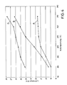
- FIGS. 4 to 6 which quantitative advantages in the heater according to the invention in comparison state of the art. 4 is that of three different ones Fan heaters transported air volume as a function of motor voltage shown.
- the characteristic curve labeled A shows the course of the curve a conventional fan heater, in which the heating element between the Air inlet openings and the fan wheel is arranged and thus already hot air hits the fan wheel. Otherwise, the air duct points as well the fan wheel has the same diameter as in the invention Arrangement.
- the structure of the wing corresponds to the conventional structure for fan wheels. The same motor was also used.
- the characteristic curve marked B belongs to a conventional one Fan heater, its fan wheel and its air duct a much larger one Have diameters than the fan heater according to the invention Embodiment.
- the characteristic curve B runs above that of A. Sie has the major disadvantage, however, that it is very steep, that is has a large dependence on voltage fluctuations. This is perceived as uncomfortable during operation.
- C we get the characteristic referred to the fan heater according to the invention. It is striking that the Characteristic curve increases continuously and thus the saturation behavior as with Characteristic curve A does not occur.
- the characteristic curve is flatter than at B, which is less susceptible to voltage fluctuations equivalent. It is of central importance that the characteristic curve C is above of the two characteristic curves A and B. This means that due to the arrangement of the heating element between the air outlet openings and the Fan wheel of a larger amount of air can be transported.
- the motor in the device according to the invention according to characteristic curve C is the same as in the devices for the characteristic curves B and A.
- the arrangement according to the characteristic curve B is also the heating element between the air intake openings and the fan wheel arranged.
- the amount of air delivered per unit of time is a function of Speed of the fan wheel shown.
- C is the characteristic of the invention Fan heater.
- the individual measuring points correspond different motor voltages between 200 V and 250 V.
- the Characteristic A belongs to the fan heater, which in Fig. 4 also belongs to the characteristic A heard.
- This fan heater has the same diameter of the air duct and the fan wheel and the same motor as in the invention Fan heater on. Only the air is in accordance with the fan heater Characteristic curve A drawn in via the heating element.
- Fig. 6 the amount of air delivered per unit of time is a function of Speed shown.
- Characteristic curve C again corresponds to that of the invention Heater.
- characteristic curve D becomes a fan heater according to the invention Identical fan heater, where the fan wheel on the fan wheel blades straight, radially extending air discharge edges.
- a disadvantage of the oblique discharge edges is the higher voltages in a slight reduction in the amount of air delivered per unit of time.
Landscapes
- Engineering & Computer Science (AREA)
- Mechanical Engineering (AREA)
- General Engineering & Computer Science (AREA)
- Physics & Mathematics (AREA)
- Thermal Sciences (AREA)
- Chemical & Material Sciences (AREA)
- Combustion & Propulsion (AREA)
- Direct Air Heating By Heater Or Combustion Gas (AREA)
- Structures Of Non-Positive Displacement Pumps (AREA)
Applications Claiming Priority (2)
| Application Number | Priority Date | Filing Date | Title |
|---|---|---|---|
| DE10110243 | 2001-03-05 | ||
| DE2001110243 DE10110243A1 (de) | 2001-03-05 | 2001-03-05 | Heizlüfter |
Publications (2)
| Publication Number | Publication Date |
|---|---|
| EP1239237A2 true EP1239237A2 (fr) | 2002-09-11 |
| EP1239237A3 EP1239237A3 (fr) | 2003-08-27 |
Family
ID=7676175
Family Applications (1)
| Application Number | Title | Priority Date | Filing Date |
|---|---|---|---|
| EP02004174A Withdrawn EP1239237A3 (fr) | 2001-03-05 | 2002-02-26 | Thermoventilateur |
Country Status (2)
| Country | Link |
|---|---|
| EP (1) | EP1239237A3 (fr) |
| DE (1) | DE10110243A1 (fr) |
Cited By (1)
| Publication number | Priority date | Publication date | Assignee | Title |
|---|---|---|---|---|
| EP1529962A3 (fr) * | 2003-11-08 | 2008-03-05 | Alstom Technology Ltd | Aube rotorique pour compresseur |
Families Citing this family (1)
| Publication number | Priority date | Publication date | Assignee | Title |
|---|---|---|---|---|
| DE102006062353A1 (de) | 2006-12-22 | 2008-06-26 | Fakir Hausgeräte GmbH | Heizlüfter |
Family Cites Families (8)
| Publication number | Priority date | Publication date | Assignee | Title |
|---|---|---|---|---|
| DE7309040U (de) * | 1973-06-20 | Siemens Ag | Axialventilator mit nachgeschaltetem Wärmetauscher | |
| CH251983A (fr) * | 1946-07-26 | 1947-11-30 | Gardiol Rene | Appareil électrique de ventilation et de chauffage. |
| DE1943094A1 (de) * | 1969-08-25 | 1971-03-04 | Harro Manias | Verfahren zur Herstellung von rasterlosen Drucktraegern |
| US4740670A (en) * | 1986-04-11 | 1988-04-26 | Taiwan Electric Heating Equipment Co. Ltd. | Electric fan heater for circulating and/or heating air |
| DE3918564A1 (de) * | 1989-06-07 | 1990-12-13 | Wolf Klimatechnik Gmbh | Luftheizer |
| DE19541782A1 (de) * | 1995-11-09 | 1997-05-15 | Gea Happel Klimatechnik | Luftheizgerät |
| JP3050144B2 (ja) * | 1996-11-12 | 2000-06-12 | ダイキン工業株式会社 | 軸流ファン |
| JP3204208B2 (ja) * | 1998-04-14 | 2001-09-04 | 松下電器産業株式会社 | 斜流送風機羽根車 |
-
2001
- 2001-03-05 DE DE2001110243 patent/DE10110243A1/de not_active Withdrawn
-
2002
- 2002-02-26 EP EP02004174A patent/EP1239237A3/fr not_active Withdrawn
Cited By (1)
| Publication number | Priority date | Publication date | Assignee | Title |
|---|---|---|---|---|
| EP1529962A3 (fr) * | 2003-11-08 | 2008-03-05 | Alstom Technology Ltd | Aube rotorique pour compresseur |
Also Published As
| Publication number | Publication date |
|---|---|
| DE10110243A1 (de) | 2002-09-12 |
| EP1239237A3 (fr) | 2003-08-27 |
Similar Documents
| Publication | Publication Date | Title |
|---|---|---|
| DE69925071T2 (de) | Kreisellüftereinheit für ein Kraftfahrzeug | |
| DE69102127T2 (de) | Lüfter, insbesondere für Kraftfahrzeuge. | |
| DE3137114C2 (fr) | ||
| DE60122323T2 (de) | Kühlventilator mit trichterförmigem mantel und entsprechender blattform | |
| DE60315959T2 (de) | Motorgekühlte lüfteranordnung mit überlappenden flügeln | |
| DE69018470T2 (de) | Gebläse mit grosser förderleistung. | |
| EP2798726B1 (fr) | Module ventilateur | |
| EP1747917A2 (fr) | Élément de chauffage | |
| DE19963411A1 (de) | Axialventilator | |
| DE69817526T2 (de) | Axiallüfter | |
| DE1488640A1 (de) | Geblaese | |
| DE2618819A1 (de) | Elektrisches haartrockengeraet | |
| DE2756800A1 (de) | Axialventilator mit hilfsfluegeln | |
| DE102013112922A1 (de) | Diagonal- oder Axiallüfter | |
| DE602004008811T2 (de) | Axiallüfter | |
| DE102019213315A1 (de) | Ventilator | |
| DE1540747A1 (de) | Verbessertes Geraet mit einem elektrischen Heizelement,einem Elektromotor und einem Geblaese | |
| DE202016106121U1 (de) | Motor mit verbessertem Aufbau zur Wärmeableitung | |
| EP0233174B1 (fr) | Système d'échange de chaleur avec un ventilateur à courant transversal | |
| DE102013209607A1 (de) | Trommeltrockner zum Trocknen von Tabak, und entsprechendes Trocknungsverfahren | |
| DE2131952A1 (de) | Ringkanalgeblaese | |
| EP1239237A2 (fr) | Thermoventilateur | |
| EP0499104A1 (fr) | Unité de conditionnement d'air | |
| DE3222164C2 (fr) | ||
| DE102021202988A1 (de) | Flügelrad für eine elektrische Maschine und elektrische Maschine |
Legal Events
| Date | Code | Title | Description |
|---|---|---|---|
| PUAI | Public reference made under article 153(3) epc to a published international application that has entered the european phase |
Free format text: ORIGINAL CODE: 0009012 |
|
| AK | Designated contracting states |
Kind code of ref document: A2 Designated state(s): AT BE CH CY DE DK ES FI FR GB GR IE IT LI LU MC NL PT SE TR |
|
| AX | Request for extension of the european patent |
Free format text: AL;LT;LV;MK;RO;SI |
|
| PUAL | Search report despatched |
Free format text: ORIGINAL CODE: 0009013 |
|
| AK | Designated contracting states |
Designated state(s): AT BE CH CY DE DK ES FI FR GB GR IE IT LI LU MC NL PT SE TR |
|
| AX | Request for extension of the european patent |
Extension state: AL LT LV MK RO SI |
|
| RIC1 | Information provided on ipc code assigned before grant |
Ipc: 7F 04D 29/38 B Ipc: 7F 24H 3/04 A |
|
| AKX | Designation fees paid | ||
| REG | Reference to a national code |
Ref country code: DE Ref legal event code: 8566 |
|
| STAA | Information on the status of an ep patent application or granted ep patent |
Free format text: STATUS: THE APPLICATION IS DEEMED TO BE WITHDRAWN |
|
| 18D | Application deemed to be withdrawn |
Effective date: 20040228 |