EP1239254A2 - Wärmetauscher - Google Patents
Wärmetauscher Download PDFInfo
- Publication number
- EP1239254A2 EP1239254A2 EP02004875A EP02004875A EP1239254A2 EP 1239254 A2 EP1239254 A2 EP 1239254A2 EP 02004875 A EP02004875 A EP 02004875A EP 02004875 A EP02004875 A EP 02004875A EP 1239254 A2 EP1239254 A2 EP 1239254A2
- Authority
- EP
- European Patent Office
- Prior art keywords
- heat exchanger
- block
- exchanger block
- exchanger according
- blocks
- Prior art date
- Legal status (The legal status is an assumption and is not a legal conclusion. Google has not performed a legal analysis and makes no representation as to the accuracy of the status listed.)
- Granted
Links
- 238000009413 insulation Methods 0.000 claims description 15
- 238000000926 separation method Methods 0.000 claims description 5
- 230000005484 gravity Effects 0.000 claims description 4
- 229910000831 Steel Inorganic materials 0.000 description 9
- 239000010959 steel Substances 0.000 description 9
- XAGFODPZIPBFFR-UHFFFAOYSA-N aluminium Chemical compound [Al] XAGFODPZIPBFFR-UHFFFAOYSA-N 0.000 description 5
- 229910052782 aluminium Inorganic materials 0.000 description 5
- 239000000725 suspension Substances 0.000 description 4
- 238000002955 isolation Methods 0.000 description 3
- 238000000034 method Methods 0.000 description 3
- 238000001816 cooling Methods 0.000 description 1
- 239000012530 fluid Substances 0.000 description 1
- 239000007789 gas Substances 0.000 description 1
- 230000003068 static effect Effects 0.000 description 1
Images
Classifications
-
- F—MECHANICAL ENGINEERING; LIGHTING; HEATING; WEAPONS; BLASTING
- F25—REFRIGERATION OR COOLING; COMBINED HEATING AND REFRIGERATION SYSTEMS; HEAT PUMP SYSTEMS; MANUFACTURE OR STORAGE OF ICE; LIQUEFACTION SOLIDIFICATION OF GASES
- F25J—LIQUEFACTION, SOLIDIFICATION OR SEPARATION OF GASES OR GASEOUS OR LIQUEFIED GASEOUS MIXTURES BY PRESSURE AND COLD TREATMENT OR BY BRINGING THEM INTO THE SUPERCRITICAL STATE
- F25J3/00—Processes or apparatus for separating the constituents of gaseous or liquefied gaseous mixtures involving the use of liquefaction or solidification
- F25J3/02—Processes or apparatus for separating the constituents of gaseous or liquefied gaseous mixtures involving the use of liquefaction or solidification by rectification, i.e. by continuous interchange of heat and material between a vapour stream and a liquid stream
- F25J3/04—Processes or apparatus for separating the constituents of gaseous or liquefied gaseous mixtures involving the use of liquefaction or solidification by rectification, i.e. by continuous interchange of heat and material between a vapour stream and a liquid stream for air
-
- F—MECHANICAL ENGINEERING; LIGHTING; HEATING; WEAPONS; BLASTING
- F25—REFRIGERATION OR COOLING; COMBINED HEATING AND REFRIGERATION SYSTEMS; HEAT PUMP SYSTEMS; MANUFACTURE OR STORAGE OF ICE; LIQUEFACTION SOLIDIFICATION OF GASES
- F25J—LIQUEFACTION, SOLIDIFICATION OR SEPARATION OF GASES OR GASEOUS OR LIQUEFIED GASEOUS MIXTURES BY PRESSURE AND COLD TREATMENT OR BY BRINGING THEM INTO THE SUPERCRITICAL STATE
- F25J3/00—Processes or apparatus for separating the constituents of gaseous or liquefied gaseous mixtures involving the use of liquefaction or solidification
- F25J3/02—Processes or apparatus for separating the constituents of gaseous or liquefied gaseous mixtures involving the use of liquefaction or solidification by rectification, i.e. by continuous interchange of heat and material between a vapour stream and a liquid stream
- F25J3/04—Processes or apparatus for separating the constituents of gaseous or liquefied gaseous mixtures involving the use of liquefaction or solidification by rectification, i.e. by continuous interchange of heat and material between a vapour stream and a liquid stream for air
- F25J3/04763—Start-up or control of the process; Details of the apparatus used
- F25J3/04866—Construction and layout of air fractionation equipments, e.g. valves, machines
- F25J3/04945—Details of internal structure; insulation and housing of the cold box
-
- F—MECHANICAL ENGINEERING; LIGHTING; HEATING; WEAPONS; BLASTING
- F25—REFRIGERATION OR COOLING; COMBINED HEATING AND REFRIGERATION SYSTEMS; HEAT PUMP SYSTEMS; MANUFACTURE OR STORAGE OF ICE; LIQUEFACTION SOLIDIFICATION OF GASES
- F25J—LIQUEFACTION, SOLIDIFICATION OR SEPARATION OF GASES OR GASEOUS OR LIQUEFIED GASEOUS MIXTURES BY PRESSURE AND COLD TREATMENT OR BY BRINGING THEM INTO THE SUPERCRITICAL STATE
- F25J5/00—Arrangements of cold exchangers or cold accumulators in separation or liquefaction plants
- F25J5/002—Arrangements of cold exchangers or cold accumulators in separation or liquefaction plants for continuously recuperating cold, i.e. in a so-called recuperative heat exchanger
-
- F—MECHANICAL ENGINEERING; LIGHTING; HEATING; WEAPONS; BLASTING
- F25—REFRIGERATION OR COOLING; COMBINED HEATING AND REFRIGERATION SYSTEMS; HEAT PUMP SYSTEMS; MANUFACTURE OR STORAGE OF ICE; LIQUEFACTION SOLIDIFICATION OF GASES
- F25J—LIQUEFACTION, SOLIDIFICATION OR SEPARATION OF GASES OR GASEOUS OR LIQUEFIED GASEOUS MIXTURES BY PRESSURE AND COLD TREATMENT OR BY BRINGING THEM INTO THE SUPERCRITICAL STATE
- F25J2290/00—Other details not covered by groups F25J2200/00 - F25J2280/00
- F25J2290/42—Modularity, pre-fabrication of modules, assembling and erection, horizontal layout, i.e. plot plan, and vertical arrangement of parts of the cryogenic unit, e.g. of the cold box
Definitions
- the invention relates to a heat exchanger with at least one Heat exchanger block and an insulation tank surrounding the heat exchanger, fastening means are provided to hang the heat exchanger block in to attach the insulation container and its use in one Cryogenic air separation plant.
- the feed air to be separated When air is decomposed at low temperatures, the feed air to be separated must be on the Process temperature are cooled. This is usually done through indirect Heat exchange of the feed air with that obtained in the air separation plant Product streams.
- the Main heat exchanger In systems in which large amounts of air are processed, the Main heat exchanger through several heat exchanger blocks connected in parallel realized. The individual heat exchanger blocks are usually as Plate heat exchanger trained.
- the main heat exchanger is thermally insulated by inserting the Heat exchanger in a thermally insulated insulation container, a so-called Cold box.
- a thermally insulated insulation container a so-called Cold box.
- Various methods are known for heat exchanger blocks in the insulation container.
- the heat exchanger blocks on stands or supports on the Place the floor or on the foundation of the insulation housing.
- the heat exchanger block is located on two opposite Side profiles attached, which then run across the isolation room Place the support on and hold the heat exchanger block. It is also possible to attach tie rods to laterally attached profiles, with the help of which Heat exchanger is suspended from the ceiling beams of the insulation room.
- WO 99/11990 describes the heat exchanger block on the warm one End, that is to say in the upper area, to be held with support brackets and at the cold end to be braced diagonally in the isolation room using rope-shaped elements.
- the object of the present invention is therefore to develop a heat exchanger which is fixed in the insulation tank so that the piping is as simple as possible and avoided or at least avoided the cable loops for the shrinkage compensation be kept small.
- the heat exchanger block is fastened in such a way that thermally induced Changes in the pipes connected to the heat exchanger block a change in position of the block can be compensated. For example, at Cool down the system's heat exchanger block with the shrinking piping moved.
- the heat exchanger block is preferably fastened in the insulation container in such a way that that its lower end can be moved in at least two spatial directions.
- the heat exchanger block is particularly preferably freely movable above its Focus hung.
- the heat exchanger block at the top end will be the warm one Feed air and the cold product gases are fed in at the lower end.
- Corresponding only experience those with the lower, cold end when starting off or changing loads noticeable changes in length of the pipes connected to the heat exchanger block, since the temperature changes at the warm end are only slight.
- the heat exchanger block can be suspended above its center of gravity its lower end can be deflected relatively easily. On the bottom end connected pipelines, the deflection of the Heat exchanger blocks cause only small forces. A Inadmissibly high stress on the pipes is avoided.
- the invention has proven particularly useful in a heat exchanger which comprises at least two, preferably at least four, heat exchanger blocks.
- the invention is particularly suitable for heat exchangers that have eight or ten Include heat exchanger blocks in two rows of four or five blocks.
- Complex piping is necessary to keep the feed air to be cooled and that in counterflow distribute the guided product flows to the individual heat exchanger blocks.
- the inventive attachment of the heat exchanger blocks simplifies the Piping, reduces the size of the insulation tank and thus leads to a clear one Cost cutting. This is especially true if the individual Heat exchanger blocks have feed and / or discharge lines that are in a common Lead manifold.
- Fastening means are preferably provided which have joints so that the heat exchanger block can be deflected around the hinge axes.
- a such gimbal suspension is relatively inexpensive feasible and has proven to be particularly cheap in practice.
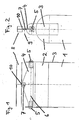
- FIGS 1 and 2 show the upper end of a heat exchanger block 1, which in the Main heat exchanger of a cryogenic air separation plant is used.
- the entire main heat exchanger consists of several such parallel connected Heat exchanger blocks 1.
- the heat exchanger block 1 has a width of up to 240 cm.
- a collector distributor 2 On the Heat exchanger block 1 is a collector distributor 2, a so-called header, attached, from which one or more pipes, not shown, lead away.
- the steel plate 4 is suspended from a double T-beam 8, which is not in the Coldbox shown is attached and carries the heat exchanger block 1.
- the joint 7 allows movement in the plane of the steel plate 4 or around an axis 9 perpendicular to the steel plate 4.
- the heat exchanger block 1 is thus cardanic by two perpendicular to each other horizontal axes 6, 9 rotatably suspended.
- the arrangement of the two aluminum plates 3 and the steel plate 4 is chosen so that the suspension point 10 is perpendicular is located above the center of gravity of the heat exchanger block 1.
- the joint 7 is arranged so that the axis 9 to the project-specific Requirements, that is to say for a specific version of the heat exchanger occurring or calculable pipe tensions is adjusted.
- Pipelines for supply and discharge to each other in heat exchange bringing fluid flows attached At the lower end of the heat exchanger block 1 are one or more, not shown Pipelines for supply and discharge to each other in heat exchange bringing fluid flows attached. With load changes and with warm and Cold running of the system experiences these pipes due to thermal conditions Length changes of about 3 to 4 mm per meter of pipeline length. Through the suspension of the heat exchanger block 1 above his The center of gravity is already relatively low at its lower end attacking forces deflected. The deflection of the heat exchanger block 1 is the same thermally induced changes in pipe length, so that on cable loops for the shrinkage compensation in the pipelines can be dispensed with.
Landscapes
- Engineering & Computer Science (AREA)
- Physics & Mathematics (AREA)
- Mechanical Engineering (AREA)
- Thermal Sciences (AREA)
- General Engineering & Computer Science (AREA)
- Heat-Exchange Devices With Radiators And Conduit Assemblies (AREA)
- Details Of Heat-Exchange And Heat-Transfer (AREA)
- Separation By Low-Temperature Treatments (AREA)
- Packages (AREA)
Abstract
Description
Claims (9)
- Wärmetauscher mit mindestens einem Wärmetauscherblock und einem den Wärmetauscher umgebenden Isolationsbehälter, wobei Befestigungsmittel vorgesehen sind, um den Wärmetauscherblock hängend in dem Isolationsbehälter zu befestigen, dadurch gekennzeichnet, dass der Wärmetauscherblock (1) in dem Isolationsbehälter bewegbar angeordnet ist.
- Wärmetauscher nach Anspruch 1, dadurch gekennzeichnet, dass das untere Ende des Wärmetauscherblocks (1) in mindestens zwei Raumrichtungen bewegbar ist.
- Wärmetauscher nach Anspruch 1 oder 2, dadurch gekennzeichnet, dass der Wärmetauscherblock (1) frei beweglich über seinem Schwerpunkt aufgehängt ist.
- Wärmetauscher nach einem der Ansprüche 1 bis 3, dadurch gekennzeichnet, dass der Wärmetauscher mindestens zwei, vorzugsweise mindestens drei Wärmetauscherblöcke (1) umfasst.
- Wärmetauscher nach Anspruch 4, dadurch gekennzeichnet, dass die Wärmetauscherblöcke (1) Zu- und/oder Ableitungen besitzen, die in eine gemeinsame Sammelleitung führen.
- Wärmetauscher nach einem der Ansprüche 1 bis 5, dadurch gekennzeichnet, dass die Befestigungsmittel Gelenke (5, 7) aufweisen.
- Wärmetauscher nach Anspruch 6, dadurch gekennzeichnet, dass die Befestigungsmittel zwei senkrecht zueinander liegende Drehachsen (6, 9) aufweisen.
- Wärmetauscher nach einem der Ansprüche 1 bis 7, dadurch gekennzeichnet, dass die Befestigungsmittel ein erstes mit dem Wärmetauscherblock (1) fest verbundenes Element (3) und ein mit dem ersten Element (3) gelenkig verbundenes zweites Element (4) aufweisen, wobei das zweite Element (4) gelenkig in dem Isolationsbehälter befestigt ist.
- Verwendung eines Wärmetauschers nach einem der Ansprüche 1 bis 8 in einer Tieftemperaturluftzerlegungsanlage, insbesondere als Hauptwärmetauscher einer Tieftemperaturluftzerlegungsanlage.
Applications Claiming Priority (2)
| Application Number | Priority Date | Filing Date | Title |
|---|---|---|---|
| DE10110704A DE10110704A1 (de) | 2001-03-06 | 2001-03-06 | Wärmetauscher |
| DE10110704 | 2001-03-06 |
Publications (3)
| Publication Number | Publication Date |
|---|---|
| EP1239254A2 true EP1239254A2 (de) | 2002-09-11 |
| EP1239254A3 EP1239254A3 (de) | 2002-12-04 |
| EP1239254B1 EP1239254B1 (de) | 2006-05-10 |
Family
ID=7676452
Family Applications (1)
| Application Number | Title | Priority Date | Filing Date |
|---|---|---|---|
| EP02004875A Expired - Lifetime EP1239254B1 (de) | 2001-03-06 | 2002-03-04 | Wärmetauscher |
Country Status (11)
| Country | Link |
|---|---|
| US (1) | US7325594B2 (de) |
| EP (1) | EP1239254B1 (de) |
| JP (1) | JP3978353B2 (de) |
| KR (1) | KR100876039B1 (de) |
| CN (1) | CN1260540C (de) |
| AT (1) | ATE325998T1 (de) |
| BR (1) | BR0200654B1 (de) |
| CA (1) | CA2375794C (de) |
| DE (2) | DE10110704A1 (de) |
| MX (1) | MXPA02002000A (de) |
| TW (1) | TW514717B (de) |
Cited By (1)
| Publication number | Priority date | Publication date | Assignee | Title |
|---|---|---|---|---|
| EP2503269A1 (de) * | 2011-03-25 | 2012-09-26 | Linde Aktiengesellschaft | Vorrichtung zur Tieftemperaturzerlegung von Luft |
Families Citing this family (5)
| Publication number | Priority date | Publication date | Assignee | Title |
|---|---|---|---|---|
| DE10331209A1 (de) * | 2003-07-10 | 2005-02-03 | Alto Deutschland Gmbh | Wärmetauscher mit Keramikboden |
| GB2422004A (en) | 2005-01-07 | 2006-07-12 | Hiflux Ltd | Plate heat exchanger |
| JP5256105B2 (ja) * | 2009-04-16 | 2013-08-07 | 三菱電機株式会社 | 冷凍空調機用熱交換器およびその熱交換器の搬送用工具 |
| FR2995672B1 (fr) * | 2012-09-19 | 2014-10-03 | Air Liquide | Echangeur de chaleur et procede d'installation d'une unite de separation de gaz comprenant de tels echangeurs de chaleur |
| US11828189B1 (en) * | 2021-12-20 | 2023-11-28 | General Electric Company | System and method for restraining heat exchanger with cable in tension |
Citations (1)
| Publication number | Priority date | Publication date | Assignee | Title |
|---|---|---|---|---|
| WO1999011990A1 (de) | 1997-08-28 | 1999-03-11 | Messer Griesheim Gmbh | Anlage zur tieftemperaturzerlegung von luft |
Family Cites Families (25)
| Publication number | Priority date | Publication date | Assignee | Title |
|---|---|---|---|---|
| US529288A (en) * | 1894-11-13 | Liquids by means of steam | ||
| DE460711C (de) * | 1926-03-14 | 1928-06-04 | Richard Pabst Dipl Ing | Vorrichtung zur Erwaermung von Badewasser |
| US1901014A (en) * | 1931-06-12 | 1933-03-14 | Creamery Package Mfg Co | Milk cooling and storing apparatus |
| US2200355A (en) * | 1932-07-28 | 1940-05-14 | Jensen Creamery Machinery Comp | Heat exchange device |
| US2057298A (en) * | 1935-02-04 | 1936-10-13 | Cherry Burrell Corp | Heat exchange device |
| US2041483A (en) * | 1935-04-23 | 1936-05-19 | Prestage Edwin | Milk pasteurizing and cooling unit |
| US3000193A (en) * | 1958-02-21 | 1961-09-19 | Hupp Corp | Air conditioning evaporators |
| GB1037056A (en) * | 1962-04-09 | 1966-07-27 | Babcock & Wilcox Ltd | Improvements in or relating to supporting means |
| GB1085361A (en) * | 1963-03-29 | 1967-09-27 | Foster Wheeler Ltd | Improvements in and relating to heat exchangers |
| US3285327A (en) * | 1964-08-05 | 1966-11-15 | Dresser Ind | Discharge cooler for rotary positive displacement vacuum pump |
| US4066119A (en) * | 1976-08-30 | 1978-01-03 | Caterpillar Tractor Co. | Rotatable radiator assembly for a vehicle |
| US4064932A (en) * | 1977-02-14 | 1977-12-27 | Hughes Aircraft Company | All climate heat exchanger unit with adjustable temperature and defrost control |
| FR2405451A1 (fr) * | 1977-10-07 | 1979-05-04 | Hamon | Echangeur de chaleur, notamment pour refrigerant atmospherique |
| US4232455A (en) * | 1977-12-03 | 1980-11-11 | Beloit Corporation | Dryer drum condensate removal apparatus |
| US4377025A (en) * | 1978-10-26 | 1983-03-22 | The Garrett Corporation | Method of mounting heat exchanger support system |
| JPS5929993A (ja) * | 1982-08-10 | 1984-02-17 | Asahi Glass Co Ltd | 横型多管式熱交換器 |
| JPS5974497A (ja) * | 1982-10-22 | 1984-04-26 | Mitsubishi Heavy Ind Ltd | 排ガス熱交換器 |
| US4852640A (en) * | 1986-03-28 | 1989-08-01 | Exothermics-Eclipse Inc. | Recuperative heat exchanger |
| US4685426A (en) * | 1986-05-05 | 1987-08-11 | The Babcock & Wilcox Company | Modular exhaust gas steam generator with common boiler casing |
| DE3734523A1 (de) * | 1987-10-13 | 1989-04-27 | Sueddeutsche Kuehler Behr | Ladeluftkuehler |
| US5131459A (en) * | 1991-10-08 | 1992-07-21 | Deltak Corporation | Heat exchanger with movable tube assemblies |
| DE4206657C2 (de) * | 1992-03-03 | 1997-01-09 | Siemens Ag | Anordnung eines Dampferzeugers in einer Tragkonstruktion |
| US5380502A (en) * | 1993-07-26 | 1995-01-10 | Atlantic Richfield Company | System for suspending reactor tubes in a reactor |
| IT234821Y1 (it) * | 1994-08-12 | 2000-03-16 | Gabriele Muzzarelli | Unita' operativa lattiero casearia polivalente, completa e autonoma per la produzione di derivati da latte |
| US6105660A (en) * | 1998-11-02 | 2000-08-22 | Textron Inc. | Oil cooler movably supported on a vehicle and method for same |
-
2001
- 2001-03-06 DE DE10110704A patent/DE10110704A1/de not_active Withdrawn
-
2002
- 2002-02-25 MX MXPA02002000A patent/MXPA02002000A/es active IP Right Grant
- 2002-02-26 KR KR1020020010160A patent/KR100876039B1/ko not_active Expired - Fee Related
- 2002-02-26 TW TW091103424A patent/TW514717B/zh not_active IP Right Cessation
- 2002-03-04 AT AT02004875T patent/ATE325998T1/de not_active IP Right Cessation
- 2002-03-04 DE DE50206714T patent/DE50206714D1/de not_active Expired - Lifetime
- 2002-03-04 EP EP02004875A patent/EP1239254B1/de not_active Expired - Lifetime
- 2002-03-05 JP JP2002058285A patent/JP3978353B2/ja not_active Expired - Fee Related
- 2002-03-05 BR BRPI0200654-5A patent/BR0200654B1/pt not_active IP Right Cessation
- 2002-03-06 CA CA2375794A patent/CA2375794C/en not_active Expired - Fee Related
- 2002-03-06 US US10/091,350 patent/US7325594B2/en not_active Expired - Fee Related
- 2002-03-06 CN CNB021068739A patent/CN1260540C/zh not_active Expired - Fee Related
Patent Citations (1)
| Publication number | Priority date | Publication date | Assignee | Title |
|---|---|---|---|---|
| WO1999011990A1 (de) | 1997-08-28 | 1999-03-11 | Messer Griesheim Gmbh | Anlage zur tieftemperaturzerlegung von luft |
Cited By (4)
| Publication number | Priority date | Publication date | Assignee | Title |
|---|---|---|---|---|
| EP2503269A1 (de) * | 2011-03-25 | 2012-09-26 | Linde Aktiengesellschaft | Vorrichtung zur Tieftemperaturzerlegung von Luft |
| CN102706097A (zh) * | 2011-03-25 | 2012-10-03 | 林德股份公司 | 低温分离空气的设备 |
| US9228778B2 (en) | 2011-03-25 | 2016-01-05 | Linde Aktiengesellschaft | Device for the low-temperature separation of air |
| CN102706097B (zh) * | 2011-03-25 | 2016-06-01 | 林德股份公司 | 低温分离空气的设备 |
Also Published As
| Publication number | Publication date |
|---|---|
| DE50206714D1 (de) | 2006-06-14 |
| US7325594B2 (en) | 2008-02-05 |
| EP1239254B1 (de) | 2006-05-10 |
| MXPA02002000A (es) | 2004-04-21 |
| JP2002303497A (ja) | 2002-10-18 |
| US20020124998A1 (en) | 2002-09-12 |
| BR0200654A (pt) | 2002-12-10 |
| CA2375794A1 (en) | 2002-09-06 |
| CA2375794C (en) | 2012-07-03 |
| KR20020071732A (ko) | 2002-09-13 |
| JP3978353B2 (ja) | 2007-09-19 |
| DE10110704A1 (de) | 2002-09-12 |
| CN1384328A (zh) | 2002-12-11 |
| ATE325998T1 (de) | 2006-06-15 |
| KR100876039B1 (ko) | 2008-12-26 |
| BR0200654B1 (pt) | 2010-11-16 |
| TW514717B (en) | 2002-12-21 |
| CN1260540C (zh) | 2006-06-21 |
| EP1239254A3 (de) | 2002-12-04 |
Similar Documents
| Publication | Publication Date | Title |
|---|---|---|
| DE19964549B4 (de) | Luftdestillationsanlage und zugehörige Kältebox | |
| DE69319761T2 (de) | Konstruktionsaufbau | |
| DE4320027C2 (de) | Verfahren zur Herstellung einer Tieftemperatur-Gastrenneinheit sowie Teileinheit, Einheit und Tieftemperaturanlage nach diesem Verfahren | |
| DE60111600T2 (de) | Wagenkasten eines Schienenfahrzeugs | |
| EP0561037A1 (de) | Vorrichtung zur Versorgung eines Kreislaufs einer Wärme- oder Kälteversorgungsanlage | |
| DE69814792T2 (de) | Verfahren zur Installation einer kryogenischen Anlage mit vormontierten Bauteilen | |
| DE102018101344A1 (de) | Kühleinheit, Anlage und Verfahren | |
| WO2013159868A2 (de) | Transportables paket mit einer coldbox,tieftemperatur-luftzerlegungsanlage und verfahren zum herstellen einer tieftemperatur-luftzerlegungsanlage | |
| EP1239254B1 (de) | Wärmetauscher | |
| DE69115930T2 (de) | Gerüst für wirbelbettbehälter | |
| DE69817042T2 (de) | Kälteaggregat | |
| DE102006052854B4 (de) | Großraumkabine zur Behandlung von Werkstücken | |
| DE102011015233A1 (de) | Vorrichtung zur Tieftemperaturzerlegung von Luft | |
| DE2743819C3 (de) | Deckenstrahlungsheizung für Hallen u.a. Bauten | |
| EP1015827B2 (de) | Anlage zur tieftemperaturzerlegung von luft | |
| DE10342788A1 (de) | Coldbox | |
| CN106223548A (zh) | 一种具有全天候自适应功能的网格式金属屋面固定装置 | |
| WO2008014899A1 (de) | Verfahren zur herstellung einer coldbox, coldbox und coldbox- paneel | |
| EP1191294B1 (de) | Trockenanlage in Paneelbauweise | |
| WO1999011990A1 (de) | Anlage zur tieftemperaturzerlegung von luft | |
| DE2526509C3 (de) | Zweistieliger Querrahmen für eine Skelettkonstruktion für Industriegebäude | |
| AT526675B1 (de) | Fahrzeugunterstand | |
| DE19713738C1 (de) | Gitterartiges Deckenelement als Kühleinrichtung | |
| DE3903147C2 (de) | ||
| CN215291810U (zh) | 一种设置有伸缩骨架的安全防护网 |
Legal Events
| Date | Code | Title | Description |
|---|---|---|---|
| PUAI | Public reference made under article 153(3) epc to a published international application that has entered the european phase |
Free format text: ORIGINAL CODE: 0009012 |
|
| AK | Designated contracting states |
Kind code of ref document: A2 Designated state(s): AT BE CH CY DE DK ES FI FR GB GR IE IT LI LU MC NL PT SE TR |
|
| AX | Request for extension of the european patent |
Free format text: AL;LT;LV;MK;RO;SI |
|
| PUAL | Search report despatched |
Free format text: ORIGINAL CODE: 0009013 |
|
| AK | Designated contracting states |
Kind code of ref document: A3 Designated state(s): AT BE CH CY DE DK ES FI FR GB GR IE IT LI LU MC NL PT SE TR |
|
| AX | Request for extension of the european patent |
Free format text: AL;LT;LV;MK;RO;SI |
|
| 17P | Request for examination filed |
Effective date: 20030509 |
|
| AKX | Designation fees paid |
Designated state(s): AT BE CH CY DE DK ES FI FR GB GR IE IT LI LU MC NL PT SE TR |
|
| 17Q | First examination report despatched |
Effective date: 20050218 |
|
| GRAP | Despatch of communication of intention to grant a patent |
Free format text: ORIGINAL CODE: EPIDOSNIGR1 |
|
| GRAS | Grant fee paid |
Free format text: ORIGINAL CODE: EPIDOSNIGR3 |
|
| GRAA | (expected) grant |
Free format text: ORIGINAL CODE: 0009210 |
|
| AK | Designated contracting states |
Kind code of ref document: B1 Designated state(s): AT BE CH CY DE DK ES FI FR GB GR IE IT LI LU MC NL PT SE TR |
|
| PG25 | Lapsed in a contracting state [announced via postgrant information from national office to epo] |
Ref country code: IT Free format text: LAPSE BECAUSE OF FAILURE TO SUBMIT A TRANSLATION OF THE DESCRIPTION OR TO PAY THE FEE WITHIN THE PRESCRIBED TIME-LIMIT;WARNING: LAPSES OF ITALIAN PATENTS WITH EFFECTIVE DATE BEFORE 2007 MAY HAVE OCCURRED AT ANY TIME BEFORE 2007. THE CORRECT EFFECTIVE DATE MAY BE DIFFERENT FROM THE ONE RECORDED. Effective date: 20060510 Ref country code: IE Free format text: LAPSE BECAUSE OF FAILURE TO SUBMIT A TRANSLATION OF THE DESCRIPTION OR TO PAY THE FEE WITHIN THE PRESCRIBED TIME-LIMIT Effective date: 20060510 Ref country code: NL Free format text: LAPSE BECAUSE OF FAILURE TO SUBMIT A TRANSLATION OF THE DESCRIPTION OR TO PAY THE FEE WITHIN THE PRESCRIBED TIME-LIMIT Effective date: 20060510 Ref country code: FI Free format text: LAPSE BECAUSE OF FAILURE TO SUBMIT A TRANSLATION OF THE DESCRIPTION OR TO PAY THE FEE WITHIN THE PRESCRIBED TIME-LIMIT Effective date: 20060510 |
|
| REG | Reference to a national code |
Ref country code: GB Ref legal event code: FG4D Free format text: NOT ENGLISH |
|
| REG | Reference to a national code |
Ref country code: CH Ref legal event code: EP |
|
| REF | Corresponds to: |
Ref document number: 50206714 Country of ref document: DE Date of ref document: 20060614 Kind code of ref document: P |
|
| REG | Reference to a national code |
Ref country code: IE Ref legal event code: FG4D Free format text: LANGUAGE OF EP DOCUMENT: GERMAN |
|
| PG25 | Lapsed in a contracting state [announced via postgrant information from national office to epo] |
Ref country code: SE Free format text: LAPSE BECAUSE OF FAILURE TO SUBMIT A TRANSLATION OF THE DESCRIPTION OR TO PAY THE FEE WITHIN THE PRESCRIBED TIME-LIMIT Effective date: 20060810 Ref country code: DK Free format text: LAPSE BECAUSE OF FAILURE TO SUBMIT A TRANSLATION OF THE DESCRIPTION OR TO PAY THE FEE WITHIN THE PRESCRIBED TIME-LIMIT Effective date: 20060810 |
|
| PG25 | Lapsed in a contracting state [announced via postgrant information from national office to epo] |
Ref country code: ES Free format text: LAPSE BECAUSE OF FAILURE TO SUBMIT A TRANSLATION OF THE DESCRIPTION OR TO PAY THE FEE WITHIN THE PRESCRIBED TIME-LIMIT Effective date: 20060821 |
|
| GBT | Gb: translation of ep patent filed (gb section 77(6)(a)/1977) |
Effective date: 20060904 |
|
| PG25 | Lapsed in a contracting state [announced via postgrant information from national office to epo] |
Ref country code: PT Free format text: LAPSE BECAUSE OF FAILURE TO SUBMIT A TRANSLATION OF THE DESCRIPTION OR TO PAY THE FEE WITHIN THE PRESCRIBED TIME-LIMIT Effective date: 20061010 |
|
| NLV1 | Nl: lapsed or annulled due to failure to fulfill the requirements of art. 29p and 29m of the patents act | ||
| ET | Fr: translation filed | ||
| REG | Reference to a national code |
Ref country code: IE Ref legal event code: FD4D |
|
| PLBE | No opposition filed within time limit |
Free format text: ORIGINAL CODE: 0009261 |
|
| STAA | Information on the status of an ep patent application or granted ep patent |
Free format text: STATUS: NO OPPOSITION FILED WITHIN TIME LIMIT |
|
| 26N | No opposition filed |
Effective date: 20070213 |
|
| REG | Reference to a national code |
Ref country code: CH Ref legal event code: PL |
|
| BERE | Be: lapsed |
Owner name: LINDE A.G. Effective date: 20070331 |
|
| PG25 | Lapsed in a contracting state [announced via postgrant information from national office to epo] |
Ref country code: BE Free format text: LAPSE BECAUSE OF NON-PAYMENT OF DUE FEES Effective date: 20070331 |
|
| PG25 | Lapsed in a contracting state [announced via postgrant information from national office to epo] |
Ref country code: MC Free format text: LAPSE BECAUSE OF NON-PAYMENT OF DUE FEES Effective date: 20070331 |
|
| PG25 | Lapsed in a contracting state [announced via postgrant information from national office to epo] |
Ref country code: CH Free format text: LAPSE BECAUSE OF NON-PAYMENT OF DUE FEES Effective date: 20070331 Ref country code: LI Free format text: LAPSE BECAUSE OF NON-PAYMENT OF DUE FEES Effective date: 20070331 |
|
| PG25 | Lapsed in a contracting state [announced via postgrant information from national office to epo] |
Ref country code: GR Free format text: LAPSE BECAUSE OF FAILURE TO SUBMIT A TRANSLATION OF THE DESCRIPTION OR TO PAY THE FEE WITHIN THE PRESCRIBED TIME-LIMIT Effective date: 20060811 |
|
| PG25 | Lapsed in a contracting state [announced via postgrant information from national office to epo] |
Ref country code: AT Free format text: LAPSE BECAUSE OF NON-PAYMENT OF DUE FEES Effective date: 20070304 |
|
| REG | Reference to a national code |
Ref country code: FR Ref legal event code: CA |
|
| PG25 | Lapsed in a contracting state [announced via postgrant information from national office to epo] |
Ref country code: CY Free format text: LAPSE BECAUSE OF FAILURE TO SUBMIT A TRANSLATION OF THE DESCRIPTION OR TO PAY THE FEE WITHIN THE PRESCRIBED TIME-LIMIT Effective date: 20060510 Ref country code: LU Free format text: LAPSE BECAUSE OF NON-PAYMENT OF DUE FEES Effective date: 20070304 |
|
| PG25 | Lapsed in a contracting state [announced via postgrant information from national office to epo] |
Ref country code: TR Free format text: LAPSE BECAUSE OF FAILURE TO SUBMIT A TRANSLATION OF THE DESCRIPTION OR TO PAY THE FEE WITHIN THE PRESCRIBED TIME-LIMIT Effective date: 20060510 |
|
| PGFP | Annual fee paid to national office [announced via postgrant information from national office to epo] |
Ref country code: GB Payment date: 20120301 Year of fee payment: 11 |
|
| GBPC | Gb: european patent ceased through non-payment of renewal fee |
Effective date: 20130304 |
|
| PG25 | Lapsed in a contracting state [announced via postgrant information from national office to epo] |
Ref country code: GB Free format text: LAPSE BECAUSE OF NON-PAYMENT OF DUE FEES Effective date: 20130304 |
|
| REG | Reference to a national code |
Ref country code: FR Ref legal event code: PLFP Year of fee payment: 15 |
|
| PGFP | Annual fee paid to national office [announced via postgrant information from national office to epo] |
Ref country code: DE Payment date: 20160302 Year of fee payment: 15 |
|
| PGFP | Annual fee paid to national office [announced via postgrant information from national office to epo] |
Ref country code: FR Payment date: 20160208 Year of fee payment: 15 |
|
| REG | Reference to a national code |
Ref country code: DE Ref legal event code: R119 Ref document number: 50206714 Country of ref document: DE |
|
| REG | Reference to a national code |
Ref country code: FR Ref legal event code: ST Effective date: 20171130 |
|
| PG25 | Lapsed in a contracting state [announced via postgrant information from national office to epo] |
Ref country code: DE Free format text: LAPSE BECAUSE OF NON-PAYMENT OF DUE FEES Effective date: 20171003 Ref country code: FR Free format text: LAPSE BECAUSE OF NON-PAYMENT OF DUE FEES Effective date: 20170331 |