EP1239267A2 - Mesure de niveau de liquide par excitation et détection de vibration magnétique - Google Patents
Mesure de niveau de liquide par excitation et détection de vibration magnétique Download PDFInfo
- Publication number
- EP1239267A2 EP1239267A2 EP02251555A EP02251555A EP1239267A2 EP 1239267 A2 EP1239267 A2 EP 1239267A2 EP 02251555 A EP02251555 A EP 02251555A EP 02251555 A EP02251555 A EP 02251555A EP 1239267 A2 EP1239267 A2 EP 1239267A2
- Authority
- EP
- European Patent Office
- Prior art keywords
- coil
- dependent
- inductance
- response
- fluid
- Prior art date
- Legal status (The legal status is an assumption and is not a legal conclusion. Google has not performed a legal analysis and makes no representation as to the accuracy of the status listed.)
- Withdrawn
Links
Images




Classifications
-
- G—PHYSICS
- G01—MEASURING; TESTING
- G01L—MEASURING FORCE, STRESS, TORQUE, WORK, MECHANICAL POWER, MECHANICAL EFFICIENCY, OR FLUID PRESSURE
- G01L9/00—Measuring steady of quasi-steady pressure of fluid or fluent solid material by electric or magnetic pressure-sensitive elements; Transmitting or indicating the displacement of mechanical pressure-sensitive elements, used to measure the steady or quasi-steady pressure of a fluid or fluent solid material, by electric or magnetic means
- G01L9/14—Measuring steady of quasi-steady pressure of fluid or fluent solid material by electric or magnetic pressure-sensitive elements; Transmitting or indicating the displacement of mechanical pressure-sensitive elements, used to measure the steady or quasi-steady pressure of a fluid or fluent solid material, by electric or magnetic means involving the displacement of magnets, e.g. electromagnets
-
- G—PHYSICS
- G01—MEASURING; TESTING
- G01F—MEASURING VOLUME, VOLUME FLOW, MASS FLOW OR LIQUID LEVEL; METERING BY VOLUME
- G01F23/00—Indicating or measuring liquid level or level of fluent solid material, e.g. indicating in terms of volume or indicating by means of an alarm
- G01F23/14—Indicating or measuring liquid level or level of fluent solid material, e.g. indicating in terms of volume or indicating by means of an alarm by measurement of pressure
- G01F23/18—Indicating, recording or alarm devices actuated electrically
-
- G—PHYSICS
- G01—MEASURING; TESTING
- G01F—MEASURING VOLUME, VOLUME FLOW, MASS FLOW OR LIQUID LEVEL; METERING BY VOLUME
- G01F23/00—Indicating or measuring liquid level or level of fluent solid material, e.g. indicating in terms of volume or indicating by means of an alarm
- G01F23/22—Indicating or measuring liquid level or level of fluent solid material, e.g. indicating in terms of volume or indicating by means of an alarm by measuring physical variables, other than linear dimensions, pressure or weight, dependent on the level to be measured, e.g. by difference of heat transfer of steam or water
- G01F23/28—Indicating or measuring liquid level or level of fluent solid material, e.g. indicating in terms of volume or indicating by means of an alarm by measuring physical variables, other than linear dimensions, pressure or weight, dependent on the level to be measured, e.g. by difference of heat transfer of steam or water by measuring the variations of parameters of electromagnetic or acoustic waves applied directly to the liquid or fluent solid material
- G01F23/296—Acoustic waves
- G01F23/2968—Transducers specially adapted for acoustic level indicators
-
- G—PHYSICS
- G01—MEASURING; TESTING
- G01L—MEASURING FORCE, STRESS, TORQUE, WORK, MECHANICAL POWER, MECHANICAL EFFICIENCY, OR FLUID PRESSURE
- G01L1/00—Measuring force or stress, in general
- G01L1/14—Measuring force or stress, in general by measuring variations in capacitance or inductance of electrical elements, e.g. by measuring variations of frequency of electrical oscillators
Definitions
- the present invention is directed to liquid-load measurements and in particular to sensors of the vibrating-diaphragm type.
- U.S. Patent No. 5,035,140 to Daniels et al. describes a sensor arrangement in which a member potentially loaded by liquid in a tank is caused to vibrate, and the resultant vibration is measured to determined whether it is consistent with the member's being loaded by the liquid. Such a sensor is employed to determine whether liquid in a tank has reached a level at which the sensor is mounted.
- U.S. Patent No. 5,345,811 to Alexandrovich et al. describes an approach that can be used to measure the density of fuel in an aircraft tank.
- the Alexandrovich et al. arrangement infers the density from the natural vibration frequency of a diaphragm as loaded by the fuel, with which the diaphragm is in contact.
- Alexandrovich et al. employ processor-based calibrations to determine coefficients in an equation relating the density to the natural frequency. With these coefficients, a processor calculates the density of the tested fluid from the observed frequency.
- Alexandrovich et al. mount and excite the diaphragm in a special fashion. Specifically, the diaphragm extends through a sealed slit in the tank wall, and the diaphragm is so excited as to assume vibration in a mode that has a node at the wall location. This allows both faces of the diaphragm to be exposed to the fuel so as to cancel out pressure effects.
- a fluid-load sensor according to claim 1.
- a method according to claim 16 The scope of the present invention extends to a computer program for performing at least some of the method steps when executed by a computational circuit.
- the diaphragm's response to flexural excitation can be determined from the coil signal induced by the moving permanent magnet's field.
- FIG. 1 depicts an embodiment of the invention in which it is applied to sensing liquid loading.
- the density of a lubricant liquid 10 in a lubricant reservoir 12 is known, and the sensor is used to indicate level.
- the sensor is used to indicate level.
- the same approach to liquid-load measurement can be used to determine the density of a fluid whose level is known.
- the reservoir 12 may be the lubricant sump of a compressor in a compressor bank, for instance.
- a compressor bank is the preferred cooling-system configuration in some commercial installations, and it is particularly important in such installations to monitor the reservoir's lubricant level so that the compressor will not have its lubricant scavenged by other compressors in the bank.
- the illustrated embodiment also simultaneously measures temperature and pressure, which are quantities that it is valuable to know in order to make system-management determinations such as whether the lubricant has absorbed excessive refrigerant.
- the present invention's approach to monitoring a fluid level is to excite a flexible diaphragm in contact with the lubricant 10 and infer the fluid's level from the diaphragm's response.
- the sensor assembly containing the diaphragm can be placed anywhere in the lubricant reservoir 12 that will permit the diaphragm to be in contact with the liquid 10 .
- FIG. 1 illustrates, though, I prefer to place the sensor assembly 14 at the bottom of a separate but connected chamber 16 .
- the chamber 16 is formed by a chamber housing 18 that a coupling 20 secures into the sight-glass port 22 commonly provided in such installations in order to monitor lubricant level visually.
- the liquid 10 is free to flow into the chamber 16 through an axially extending slit 23 in an overlapped sleeve 24 within the chamber.
- the sleeve serves to form a uniform measurement cross-section and effectively to isolate the sensor assembly 14 from the compressor sump.
- the sleeve 24 may consist, for instance, of a coiled strip of 0.010-inch- (0.025-cm-) thick shim stock formed into a shape that is nearly circular, with the exception that its free ends 25 and 26 overlap and are spaced slightly apart by several small bent-back tabs 27 that free end 26 forms.
- a plug 28 caps the chamber.
- the cavity at the base of the plug 28 may be covered with a perforated plate 29 , which cooperates with the sleeve 24 's smooth but acoustically lossy surface to attenuate acoustic modes that diaphragm excitation can cause.
- FIG. 2 shows that the sensor assembly 14 includes a diaphragm 30 supported by a sensor housing 32 to which it is attached by solder or brazing.
- the housing forms the exterior threads by which the assembly is mounted in FIG. 1 's chamber housing 18 .
- the diaphragm 30 is shown as a hydro-formed element, but it could be fabricated in some other fashion; it could be a welded bellows, for instance.
- the preferred embodiment's diaphragm material is beryllium copper, but numerous suitable alternative materials are applicable. In some embodiments it may also be desirable to use a mechanical spring to augment the diaphragm's elastic properties, particularly if the bellows is made of a material such as phosphor bronze or stainless steel.
- the illustrated embodiment's diaphragm mounting is so simple because the present invention's approach to dealing with pressure effects, which will be explained below, eliminates the need to use complicated pressure-equalizing techniques for mounting.
- the illustrated embodiment includes a coil 34 .
- the coil 34 may include, say, 1400 turns of #38 magnet wire wound on a bobbin secured by a magnetically-permeable retaining screw 36 , such as a #4-40 steel screw, to a magnetically permeable base member 37 retained by a rolled or crimped lip 38 that the sensor housing 32 forms.
- a magnetically permeable sleeve 39 preferably having a 0.028-inch- (0.071-cm-) thick steel wall, surrounds the coil 34 .
- a magnetically permeable pedestal 40 is welded, soldered, or similarly attached to the inside of the diaphragm 30 . This pedestal forms a face that may, for example, be a 0.563-inch- (1.430-cm-) diameter steel disk having a thickness of 0.020 inch (0.051 cm).
- a permanent magnet 42 is mounted on the pedestal's face.
- the magnet may, for instance, be a 0.25-inch (0.64-cm) diameter neodymium-iron-boron axially magnetized disk whose thickness is 0.1 inch (0.3 cm).
- Other rare-earth, high-field-strength magnets having high Curie temperatures are also suitable.
- Acceptable materials for the magnetically permeable components include metals having substantial iron content such as soft iron and carbon steel.
- a non-magnetic mechanical stop 44 protects the diaphragm from excessive deformation by stopping the pedestal 40 and magnet 42 before external pressure deforms the diaphragm too far toward the coil 34 .
- the bellows diaphragm's elastic properties determine the maximum permissible bellows stroke, which may be of the order of 0.020 to 0.040 inch (0.051 to 0.102 cm).
- Base 37 , sleeve 39 , pedestal 40 , magnet 42 , and retaining screw 36 form a magnetically biased magnetic circuit in which the magnet 42 is nested co-axially with the coil 34 and separated from it by a sensing gap 46 .
- the flux path between the magnet and the coil spans the gap 46 between the tip of the magnet 42 and the top of the retaining screw 36 and between the tip of the pedestal 40 and the top edge of the coil retaining sleeve 39 .
- Gaps of approximately 0.1 inch (0.3 cm) make the coil inductance relatively sensitive to the magnet 42 's position, and this sensitivity is desirable for reasons that will be set forth below.
- Small slots 47 in each side of the retaining sleeve 39 permit connections between the coil and a cable 48 's conductors.
- a strain-relief clamp 49 secures the cable 48 to the sensor body.
- the illustrated embodiment determines temperature and pressure by repeatedly measuring the coil's resistance and inductance. It also repeatedly displaces the diaphragm and its attached magnet from their stable positions by pulsing the coil, as will be described in more detail below.
- the magnet's resultant oscillations induce oscillatory coil voltage whose frequency is related to the fluid level and, to some extent, the ambient pressure.
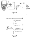
- the cable 48 extends through a hole in the base 37 and runs between the coil 34 and computation circuitry depicted in FIG. 3 . Since the illustrated embodiment uses only the coil for all measurements, a simple coaxial cable is all that is required.
- the coil 34 is one leg of a standard bridge-type detection circuit that the computation circuit includes. Periodically ⁇ say, every second or two ⁇ circuitry not shown applies a transient voltage step to the bridge's excitation point 50 . In the illustrated embodiment this step is -0.33 volt and persists for 3.5 milliseconds, as FIG. 4 's top trace indicates. That step's amplitude is low because its purpose is to elicit a coil response under quiescent-diaphragm conditions. As the middle trace indicates, circuitry not shown applies a brief intense impulse immediately thereafter to the coil at another excitation point 52 . In the illustrated embodiment, this coil-excitation pulse's magnitude is 12 volts and lasts for 300 microseconds.
- the resultant bridge-detector output appears at node 54 , whose signal is the input to a computer 56 's analog-to-digital port. From the resultant data, the computer 56 determines temperature, pressure, and level in a manner that will now be described.
- FIG. 4 shows that the response at node 54 to the step stimulus at node 52 includes three segments labeled A, B, and C .
- Segments A and B are within the transient part of the response to the step and are associated with the coil's inductive characteristic.
- Segment C is well past the initial transient, so it can be thought of as a constant-stimulus response, and its level is the same as what the output would be if the coil were purely resistive. Since coil resistance depends on temperature, the computer 56 uses the segment- C level to determine coil temperature. Beginning at the onset of the bridge excitation, the illustrated embodiment samples the output (node- 54 ) waveform at a data rate of 100,000 samples per second.
- Time segment C is chosen as samples 300 through 330 (3.0 through 3.3 milliseconds).
- the computer takes the average of twenty-one data points, and in the illustrated embodiment the (temperature-dependent) result c is related to temperature T in accordance with a function that FIG. 5 illustrates.
- the corresponding functions for other embodiments will not in general be the same as that of FIG. 5 .
- time segments A and B are contiguous, with segment A beginning at the first sampled waveform value. Their combined duration is chosen to span approximately one characteristic time. For example, time segment A has been chosen in the illustrated embodiment as the first thirty-two sample intervals and time segment B as the next thirty-two. Since the sample rate is 100,000 samples per second, the resultant data cover the first 640 microseconds.
- the computer uses a ratio b / a to characterize the transient decay, where a is the result of subtracting the average segment- C sample value from the average segment- A sample value and b is the result of subtracting the average segment- C sample value from the average segment- B sample value.
- the characteristic time t c is related to the ratio b / a in the following way.
- t c t 1 /ln( a / b ).
- t 1 is the time associated with the end of segment A (320 microseconds in the example above) and segments A and B are assumed to be equal in duration.
- the computer 56 infers pressure from the inductance-dependent ratio b / a ; pressure affects the magnetic-circuit gap and thus the inductance, so the ratio b / a depends on pressure. But that ratio is also temperature-dependent, since temperature affects coil resistance and magnetic factors such as the magnetic-circuit components' permeabilities and the permanent magnet's field strength.
- the computer uses a compensation function that has been determined during calibration by observing b / a changes that result from varying the temperature without changing the pressure. (The term calibration here is not intended to suggest that the function-determining data must be taken for every sensor system made.
- FIG. 6 shows a typical relationship thus determined for a fixed inductance.
- the pressure P can then be computed from the temperature-corrected ratio ( b / a ) 1 in accordance with a best-fit polynomial approximation to previously obtained calibration data.
- the system has thus inferred static pressure from the bridge-circuit response, depicted by FIG. 4 's bottom-plot segments A , B , and C , to the relatively long-duration initial step represented by the left portion of FIG. 4 's top plot.
- the measurements taken to obtain this value resulted from a measurement made with the diaphragm in its quiescent state; the small step signal is not large enough to cause any significant diaphragm flexure.
- the measurements to which the computation circuit next turns are made while the diaphragm is vibrating. It determines fluid level from a portion, represented by the bottom plot's segment D , of the bridge response to the coil-excitation pulse that FIG. 4 's middle plot represents. That pulse results in flexural diaphragm oscillations, and the resultant electromotive force caused by the magnet's movement with respect to the coil causes the segment D output to reflect these oscillations. As the fluid level increases, the resultant mass-loading increase reduces the flexural frequency. So the computer 56 infers the mass load by spectrally analyzing the response's segment D in a manner that will now be described.
- the illustrated embodiment starts by sampling a 5-millisecond record in time segment D that begins 9 milliseconds after the first bridge excitation.
- the system suppresses noise by so filtering the data as to limit it to a frequency band of 900 Hz to 5000 Hz. It subjects the resultant, filtered data to a spectral analysis to obtain the oscillation frequency.
- spectral analysis is not crucial ⁇ various approaches such as baseline-crossing timing, etc. may be employed, for instance ⁇ the illustrated embodiment employs a discrete Fourier transform for that purpose.
- the frequency of the spectral analysis's peak output is the quantity from which the system infers fluid level.
- This flexural spectral peak frequency is dependent not only on fluid level but also, to some extent, on pressure.
- One might therefore infer fluid level by employing a two-dimensional look-up-table in which the inputs are pressure and frequency and the table contents are fluid-level values recorded in a calibration operation for those pressure-frequency combinations. In the ranges for which the illustrated embodiment is intended, though, I have observed a relationship in such data that enables the illustrated embodiment to approximate the same result in a less data-intensive way.
- the system multiplies the frequency of the spectral analysis's spectral-peak output by the pressure-correction factor for the just-measured pressure to determine what the frequency for the current fluid level would have been at the reference pressure. That level can then be inferred from a reference-pressure relationship determined at calibration time between frequency and fluid level.
- FIG. 10 illustrates how gap size was selected in the illustrated embodiment. That drawing shows that the inductance for high gap sizes approaches the unbiased-circuit value of FIG. 10 's upper plot 62 .
- Plot 62 represents the values in which FIG. 2 's arrangement would result if the permanent magnet were replaced with a steel disc of the same size.
- plot 60 shows that the magnetic circuit remains somewhat unsaturated even at a gap size of zero. Since the sensitivity-indicating slope falls off greatly above 0.10 inch (2.5 mm), which is the thickness of the permanent magnet 42 , the uncompressed gap sized is chosen to approximate that magnet's thickness.
Landscapes
- Physics & Mathematics (AREA)
- General Physics & Mathematics (AREA)
- Fluid Mechanics (AREA)
- Electromagnetism (AREA)
- Acoustics & Sound (AREA)
- Thermal Sciences (AREA)
- Measuring Fluid Pressure (AREA)
- Level Indicators Using A Float (AREA)
Applications Claiming Priority (2)
| Application Number | Priority Date | Filing Date | Title |
|---|---|---|---|
| US801362 | 2001-03-07 | ||
| US09/801,362 US6539806B2 (en) | 2001-03-07 | 2001-03-07 | Fluid-load measurement by magnetic excitation and vibration sensing of a fluid-load-sensitive diaphragm |
Publications (2)
| Publication Number | Publication Date |
|---|---|
| EP1239267A2 true EP1239267A2 (fr) | 2002-09-11 |
| EP1239267A3 EP1239267A3 (fr) | 2003-10-15 |
Family
ID=25180901
Family Applications (1)
| Application Number | Title | Priority Date | Filing Date |
|---|---|---|---|
| EP02251555A Withdrawn EP1239267A3 (fr) | 2001-03-07 | 2002-03-06 | Mesure de niveau de liquide par excitation et détection de vibration magnétique |
Country Status (2)
| Country | Link |
|---|---|
| US (1) | US6539806B2 (fr) |
| EP (1) | EP1239267A3 (fr) |
Cited By (3)
| Publication number | Priority date | Publication date | Assignee | Title |
|---|---|---|---|---|
| EP1279938A1 (fr) * | 2001-07-24 | 2003-01-29 | Starr Johnson | Dispositif de detection de charge utilisant saturation magnétique |
| WO2015028179A1 (fr) * | 2013-08-28 | 2015-03-05 | Endress+Hauser Gmbh+Co. Kg | Dispositif de détermination ou de surveillance d'une grandeur de processus en automatisme |
| WO2014195076A3 (fr) * | 2013-06-06 | 2015-04-02 | Vega Grieshaber Kg | Appareil de mesure |
Families Citing this family (13)
| Publication number | Priority date | Publication date | Assignee | Title |
|---|---|---|---|---|
| US7162918B2 (en) * | 2001-05-15 | 2007-01-16 | Baker Hughes Incorporated | Method and apparatus for downhole fluid characterization using flexural mechanical resonators |
| US6600882B1 (en) * | 2002-05-30 | 2003-07-29 | Lexmark International, Inc. | Measuring toner level in a closed container |
| US20040093951A1 (en) * | 2002-11-20 | 2004-05-20 | Viola Jeffrey L. | Magnetoelastic pressure sensor |
| FR2869410B1 (fr) * | 2004-04-26 | 2006-06-16 | Michelin Soc Tech | Compteur de rotations de pneumatique |
| US20080003120A1 (en) * | 2006-06-30 | 2008-01-03 | Meza Humberto V | Pump apparatus and method |
| US20090107248A1 (en) * | 2007-10-24 | 2009-04-30 | Thaddeus Schroeder | Magnetostrictive sensor with uniform stress |
| IT1391302B1 (it) * | 2008-10-28 | 2011-12-01 | Elbi Int Spa | Dispositivo rilevatore del livello di un liquido in un contenitore, in particolare del bagno di lavaggio in una macchina lavatrice |
| DE102008044125A1 (de) * | 2008-11-27 | 2010-06-02 | Robert Bosch Gmbh | Sensoranordnung mit einem magnetoelastischen Verformungselement |
| US8502867B2 (en) * | 2010-03-19 | 2013-08-06 | Lightspeed Genomics, Inc. | Synthetic aperture optics imaging method using minimum selective excitation patterns |
| CN102954853B (zh) * | 2011-08-22 | 2015-06-10 | 关隆股份有限公司 | 压力感测装置及其压力感测电路 |
| DE102013111778B3 (de) * | 2013-10-25 | 2015-04-30 | Bürkert Werke GmbH | Mikrofluidische Geräteeinheit |
| CN112254766B (zh) * | 2020-10-19 | 2022-02-08 | 三峡大学 | 铁塔应力、振动检测装置 |
| GB2623327B (en) * | 2022-10-11 | 2024-10-16 | Hydro Int Ltd | A level sensing system and a method of operating a level sensing system |
Family Cites Families (45)
| Publication number | Priority date | Publication date | Assignee | Title |
|---|---|---|---|---|
| US3643153A (en) | 1968-09-24 | 1972-02-15 | Gen Motors Corp | Temperature stabilization of transistor voltage regulators |
| US3693445A (en) | 1970-06-26 | 1972-09-26 | Sven J Johnson | Liquid level measurement device |
| US3820098A (en) | 1972-04-18 | 1974-06-25 | T Demyon | Electrical and visual fluid level sensor |
| GB1512233A (en) * | 1974-03-20 | 1978-05-24 | Matsushita Electric Industrial Co Ltd | Piezoelectric presence sensitive apparatus |
| US3967490A (en) | 1975-06-27 | 1976-07-06 | International Telephone And Telegraph Corporation | Vibration densitometer |
| JPS5212860A (en) | 1975-07-21 | 1977-01-31 | Sanko Kuki Sochi Kk | Level detector |
| SE407980B (sv) | 1977-02-17 | 1979-04-30 | Egnell Axel | Anordning for indikering av en vetskas niva och densitet i en tank |
| US4112760A (en) | 1977-04-25 | 1978-09-12 | Texaco Inc. | Liquid level measuring device |
| DE2725543A1 (de) | 1977-06-07 | 1978-12-21 | Bosch Gmbh Robert | Druckmessdose, insbesondere zur messung des druckes im ansaugrohr von brennkraftmaschinen |
| US4193291A (en) | 1978-02-27 | 1980-03-18 | Panametrics, Inc. | Slow torsional wave densitometer |
| FR2457478A1 (fr) | 1979-05-23 | 1980-12-19 | Motobecane Ateliers | Dispositif de visualisation du niveau d'un fluide contenu dans un reservoir |
| US4339955A (en) | 1980-08-29 | 1982-07-20 | Aisin Seiki Company, Ltd. | Pressure sensor |
| US4424705A (en) | 1980-12-26 | 1984-01-10 | Nippon Soken, Inc. | Engine knock sensing apparatus |
| US4458196A (en) | 1981-08-05 | 1984-07-03 | John Fluke Mfg. Co., Inc. | Method and apparatus for high speed resistance, inductance and capacitance measurement |
| CH647596A5 (fr) | 1982-04-01 | 1985-01-31 | Battelle Memorial Institute | Procede pour determiner le volume de liquide contenu dans un recipient ferme et dispositif pour la mise en oeuvre de ce procede. |
| JPS59174729A (ja) * | 1983-03-25 | 1984-10-03 | Seiko Instr & Electronics Ltd | 圧力センサ− |
| EP0126846B1 (fr) | 1983-04-21 | 1990-08-01 | WABCO Westinghouse Fahrzeugbremsen GmbH | Capteur inductif |
| US4526480A (en) | 1983-06-21 | 1985-07-02 | Quartztronics, Inc. | Fluid density temperature measurement apparatus and method |
| US4545245A (en) | 1983-11-09 | 1985-10-08 | Simmonds Precision Products, Inc. | Liquid level sensor using sonic methods |
| US4627292A (en) | 1984-07-03 | 1986-12-09 | Randek Inc. | AC transducers, methods and systems |
| DE3544809A1 (de) | 1985-10-02 | 1987-04-02 | Turck Werner Kg | Magnetfeldabhaengiger, elektronischer annaeherungsschalter |
| US4740726A (en) | 1986-07-21 | 1988-04-26 | Nohken Inc. | Vibrator-type level sensor |
| GB2200211B (en) | 1986-12-08 | 1991-01-16 | Fuji Electric Co Ltd | Vibration-type transducer |
| GB8705757D0 (en) | 1987-03-11 | 1987-04-15 | Schlumberger Electronics Uk | Fluid transducer |
| DE3807015A1 (de) | 1987-04-29 | 1988-11-10 | Wabco Westinghouse Fahrzeug | Verfahren und schaltung zur messung einer induktivitaet |
| DE3738515A1 (de) | 1987-11-13 | 1989-05-24 | Bosch Gmbh Robert | Fuellstandsanzeiger |
| US4864232A (en) | 1988-03-07 | 1989-09-05 | Sunpower, Inc. | Temperature compensation for displacement transducer |
| US5035140A (en) | 1988-11-03 | 1991-07-30 | The Boeing Company | Self cleaning liquid level detector |
| EP0487586A1 (fr) | 1989-08-17 | 1992-06-03 | Microbiological Research Authority | Densitometre |
| US5074148A (en) | 1990-01-05 | 1991-12-24 | Lew Hyok S | Resonance frequency liquid level sensor |
| US5054318A (en) | 1990-02-09 | 1991-10-08 | Lew Hyok S | Resonance frequency liquid level sensor |
| US5351004A (en) | 1991-10-15 | 1994-09-27 | Eldec Corporation | Saturable core proximity sensor including a flux director and a magnetic target element |
| US5285154A (en) | 1991-10-15 | 1994-02-08 | Eldec Corporation | Saturable core proximity sensor aligned perpendicular to a magnet target having a plate and a non-magnetic metal housing |
| FR2684248B1 (fr) | 1991-11-22 | 1997-04-30 | Pioch Sa | Appareil electronique de mesure et de protection du fonctionnement du transformateur a huile. |
| DE4141065A1 (de) | 1991-12-13 | 1993-06-17 | Vdo Schindling | Verfahren zur temperaturkompensation von induktiven sensoren |
| US5184510A (en) | 1991-12-23 | 1993-02-09 | Ford Motor Company | Liquid level sensor |
| US5345811A (en) | 1992-04-01 | 1994-09-13 | Parker Hannifin Corporation | Fluid density sensor and system |
| US5359902A (en) | 1993-07-15 | 1994-11-01 | Bolt Beranek And Newman Inc. | Load cell |
| US5569866A (en) | 1994-11-02 | 1996-10-29 | Allison; Malcolm M. | Force measuring device |
| US5600997A (en) | 1995-08-11 | 1997-02-11 | Itt Corporation | Carrier frequency sensing of fluids in vessels |
| US5929391A (en) | 1996-05-02 | 1999-07-27 | Measurement Specialties, Inc. | Load cell for an electrical weighing scale |
| US5743138A (en) | 1997-01-22 | 1998-04-28 | Chartered Semiconductor Manufacturing Ltd. | Spirally fluted float |
| US6089098A (en) * | 1998-04-16 | 2000-07-18 | Dwyer Instruments, Inc. | Differential pressure switch having an isolated hall effect sensor |
| US6016707A (en) * | 1998-04-29 | 2000-01-25 | Lin; Chih-Lung | Non-intrusive pressure variation monitoring device adapted to monitor abdominal pressure in pregnant women |
| US6079266A (en) * | 1999-04-01 | 2000-06-27 | Starr-Johnson | Fluid-level measurement by dynamic excitation of a pressure- and fluid-load-sensitive diaphragm |
-
2001
- 2001-03-07 US US09/801,362 patent/US6539806B2/en not_active Expired - Fee Related
-
2002
- 2002-03-06 EP EP02251555A patent/EP1239267A3/fr not_active Withdrawn
Cited By (5)
| Publication number | Priority date | Publication date | Assignee | Title |
|---|---|---|---|---|
| US6591688B2 (en) | 2001-03-07 | 2003-07-15 | Starr-Johnson | Load sensing by partial magnetic saturation |
| EP1279938A1 (fr) * | 2001-07-24 | 2003-01-29 | Starr Johnson | Dispositif de detection de charge utilisant saturation magnétique |
| WO2014195076A3 (fr) * | 2013-06-06 | 2015-04-02 | Vega Grieshaber Kg | Appareil de mesure |
| WO2015028179A1 (fr) * | 2013-08-28 | 2015-03-05 | Endress+Hauser Gmbh+Co. Kg | Dispositif de détermination ou de surveillance d'une grandeur de processus en automatisme |
| US10591443B2 (en) | 2013-08-28 | 2020-03-17 | Endress+Hauser SE+Co. KG | Apparatus for determining or monitoring a process variable of automation technology |
Also Published As
| Publication number | Publication date |
|---|---|
| EP1239267A3 (fr) | 2003-10-15 |
| US20020124645A1 (en) | 2002-09-12 |
| US6539806B2 (en) | 2003-04-01 |
Similar Documents
| Publication | Publication Date | Title |
|---|---|---|
| US6539806B2 (en) | Fluid-load measurement by magnetic excitation and vibration sensing of a fluid-load-sensitive diaphragm | |
| US2319219A (en) | Pressure indicating apparatus | |
| EP1279938B1 (fr) | Dispositif de detection de charge utilisant saturation magnétique | |
| CN86108110A (zh) | 音叉振动式粘度计 | |
| US3677067A (en) | Densitometer | |
| US6941824B2 (en) | Magnetic force sensor and control circuit for same | |
| US6079266A (en) | Fluid-level measurement by dynamic excitation of a pressure- and fluid-load-sensitive diaphragm | |
| CA2662527A1 (fr) | Capteur ameliore | |
| US5528933A (en) | Dynamic volumetric instrument gauge | |
| US20060010963A1 (en) | Measurement of viscosity using magnetostrictive particle sensors | |
| US4350041A (en) | System and method for measurement of dynamic angular or linear displacement | |
| JPH10132790A (ja) | 磁性粉濃度測定装置 | |
| JPH10314122A (ja) | 生体表面部の力学特性測定のためのセンサ内蔵形加振器 | |
| US5301540A (en) | Probe for measuring the viscosity of liquids | |
| US4255973A (en) | Digital pressure transducer for use at high temperatures | |
| JP2913025B2 (ja) | 圧覚検出方法及び圧覚センサ | |
| WO2003016891A2 (fr) | Capteur et procede permettant la mesure de micro-deformations statiques et dynamiques | |
| US20040079160A1 (en) | Pressure transducer | |
| SU1597687A1 (ru) | Устройство дл измерени твердости | |
| WO2001061312A1 (fr) | Procede de determination de la viscosite | |
| SU1010553A1 (ru) | Способ определени активных механических сопротивлений ферромагнитных жидкостей в магнитном поле | |
| SU1244559A1 (ru) | Электроакустический твердомер | |
| SU1408268A1 (ru) | Устройство дл измерени давлени ударной волны | |
| RU2039992C1 (ru) | Датчик скорости потока жидкости | |
| JPH0132445B2 (fr) |
Legal Events
| Date | Code | Title | Description |
|---|---|---|---|
| PUAI | Public reference made under article 153(3) epc to a published international application that has entered the european phase |
Free format text: ORIGINAL CODE: 0009012 |
|
| AK | Designated contracting states |
Kind code of ref document: A2 Designated state(s): AT BE CH CY DE DK ES FI FR GB GR IE IT LI LU MC NL PT SE TR |
|
| AX | Request for extension of the european patent |
Free format text: AL;LT;LV;MK;RO;SI |
|
| PUAL | Search report despatched |
Free format text: ORIGINAL CODE: 0009013 |
|
| AK | Designated contracting states |
Kind code of ref document: A3 Designated state(s): AT BE CH CY DE DK ES FI FR GB GR IE IT LI LU MC NL PT SE TR |
|
| AX | Request for extension of the european patent |
Extension state: AL LT LV MK RO SI |
|
| 17P | Request for examination filed |
Effective date: 20040415 |
|
| AKX | Designation fees paid |
Designated state(s): DE FR GB |
|
| 17Q | First examination report despatched |
Effective date: 20060919 |
|
| STAA | Information on the status of an ep patent application or granted ep patent |
Free format text: STATUS: THE APPLICATION IS DEEMED TO BE WITHDRAWN |
|
| 18D | Application deemed to be withdrawn |
Effective date: 20091001 |